MODELLING AND SIMULATION OF
SAPONIFICATION REACTION IN DIFFERENT TYPE
OF REACTOR
Mrs.Kirti Bhushan Zare
1, Ramteke Sayali Sunil
2, Mohite Sapna Anil
3 1, 2, 3Chemical Engineering, D.Y. Patil Institute of Engineering,
Management and Research, Akurdi, Pune, (India)
ABSTRACT
This work presents the kinetic modelling and simulation of saponification of ethyl acetate in the presence of
Sodium hydroxide in a plug flow reactor, Continues stirred tank reactor using Aspen Plus simulation Software.
The continuous flow stirred-tank reactor (CSTR), also known as vat- or back mix reactor, is a common ideal
reactor type in chemical engineering. A CSTR often refers to a model used to estimate the key unit operation
variables when using a continuous agitated-tank reactor to reach a specified output. Plug flow reactors are
widely used in the industry due to the non-mixing property. The use of plug flow reactors becomes significant
when there is a need for continuous large scale reaction or fast reaction. Plug flow reactors have a high
volumetric unit conversion as the occurrence for side reactions is minimum.
Keywords: Modelling, Simulation. Plug flow reactor, continuous flow stirred-tank reactor.
I. INTRODUCTION
Tubular reactor, the feed enters at one end of a cylindrical tube and the product stream leaves at the other end.
The long tube and the lack of stirring prevent complete mixing of the fluid in the tube. Hence the properties of
the flowing stream will vary from one point to another, namely in both radial and axial directions. In the ideal
tubular reactor, which is called the “plug flow” reactor, specific assumptions are made about the extent of
mixing: no mixing in the axial direction, i.e., the direction of flow complete mixing in the radial direction
uniform velocity profile across the radius. The absence of longitudinal mixing is what defines this type of
reactor[1]. The validity of the assumptions will depend on the geometry of the reactor and the flow conditions.
Deviations, which are frequent but not always important, are of two kinds:
1. Mixing in longitudinal direction due to vortices and turbulence
2. Incomplete mixing in radial direction in laminar flow conditions
Continuous stirred tank reactors (are used very commonly in industrial processes. For this type of reactor,
mixing is complete, so that the temperature and the composition of the reaction Mixture are uniform in all parts
of the vessel and are the same as those in the exit stream [2].
Three stages of the continuous operation of a CSTR can be modeled.
2.From overflow to steady state
3.Steady state operation
II. RELATED DESIGN
Design of Plug flow reactor:
Figure 2.1 Plug Flow Reactor
For a time element
t and a volume element
V at steady state, the mass balance for species
„i‟ is given by ,
1
...……….(1)
where
v: total volumetric flow rate
CA : concentration of reactant A
rA : rate of disappearance of reactant A
Dividing Eq 1 by
V and
t results in Eq.2
……….(2
)
and taking limit as
V
0 gives
………(3)
A0 (inlet concentration of reactant A)
At the exit:
V = VR (total reactor volume)
CA= CA (exit conversion)
...(4
)
……
………(5
)
………(6)
Combining equations 4, 5 & 6 the following expression is obtained
CONTINUOUS FLOW STIRRED-TANK REACTOR
Figure 2.2 Continuous Flow Stirred-Tank Reactor
One stage:
This stage is semi batch. There is no output because the reactor contents do not yet reach the overflow level.
With assuming that the saponification reaction of ethyl acetate with sodium hydroxide is second order overall, a
material balance on either NaOH or ethyl acetate (both reactants are at the same concentration and flow rate).
Or
where
C = concentration
C0 = initial concentration
M= volumetric flow rate
k = reaction rate constant
t = time, (min)
V =volume of reactor
But „V‟ is a function of time, and since the system is of constant density and flow rate, a total mass balance
gives
Stage Two
The second stage is continuous but not yet steady. The concentration is changing with time but the volume of
the reactants is constant.
rate of accumulation = rate of input - rate of output - rate of consumption
Stage Three
rate of input = rate of output + rate of consumption
The calculation of the specific rate constant k can be
III.EXPERIMENTAL WORK:
PLUG FLOW REACTOR:
1. Prepare 100 ml of 0.05 M NaOH solution in a 1000 ml beaker, record conductivity data.
2. Add 100 ml distilled water to the beaker to dilute the NaOH solution, make sure it is perfectly mixed, and
record conductivity data. Repeat this step six more times to prepare a calibration curve.
3. Prepare 5 L of 0.05 M ethyl acetate and 0.05 M NaOH solutions. Pour these solutions into the feed tanks.
4. Adjust a constant flow rate by setting the pump speeds of both reactants.
5. Record the conductivity when steady state is reached
Continuous flow stirred-tank reactor:
1. Prepare 100 ml of 0.05 M NaOH solution in a 1000 ml beaker, record conductivity data.
2. Add 25 ml distilled water to the beaker to dilute the NaOH solution, make sure it is perfectly mixed, and
record conductivity data. Repeat this step three more times (add 40, 80 and 250 ml distilled water) to prepare a
calibration curve.
3. Make up 4 liter batches of 0.05 M sodium hydroxide and 0.05 M ethyl acetate.
4. Remove the lids of the reagent vessels and carefully fill the reagents. Refit the lids.
5. Set the pump speeds of both reactants to give 50 ml/min flow rate.
6. Set the agitator speed controller to 7.0.
7. Switch on the feed pumps and agitator motor. Start the stopwatch.
8. Collect conductivity data each minute for 45 minutes
IV. RESULIT:
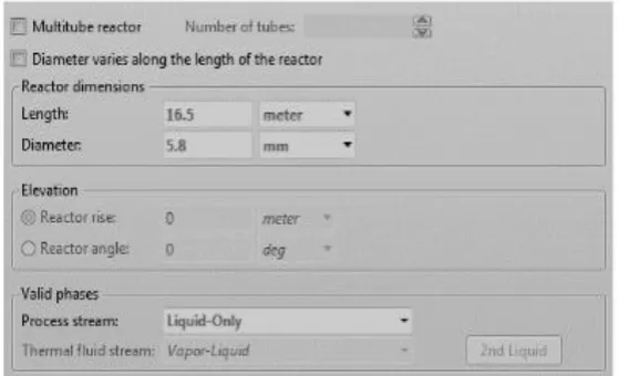
Figure 4.2 PFR Configuration
Graph No 4.2 Ethyl acetate mole fraction vs PFR at 45
0C
Graph No 4.3 Ethyl Variation of sodium acetate flow rate with reactor temperature
1.Effect of Reactant Flow Rates on the Reaction
A sensitivity analysis was done in Aspen Plus model to investigate the effect of reactant flow rates towards the
reaction. The mole fractions of sodium acetate vary for different flow rates of NaOH and ethyl acetate. It shows
that in each case the highest mole fraction of sodium acetate can be achieved when equal flow rates of NaOH
and ethyl acetate are pumped to the plug flow reactor. According to the stoichiometry of [7] it is clear that equal
amounts of reactants are needed to obtain the highest yield. When the flow rate of ethyl acetate exceeds the flow
rate of NaOH as there is no more NaOH left in the reawith ethyl acetate, the excess ethyl acetate remains in the
Variation of ethyl acetate mole fraction with acetate and NaOH flow rates.
2. Effect of Reactant Flow Rates on the Reaction
A sensitivity analysis was done in Aspen Plus model to investigate the effect of reactant flow rates towards the
how the mole fractions of sodium acetate vary for different flow rates of NaOH and ethyl acetate. It shows that
in each case the highest mole fraction of sodium acetate can be achieved when equal flow rates of NaOH and
flow reactor. According [6] it is clear that equal amounts of reactants are needed to obtain the highest yield.
3. Volume Comparison of CSTR and PFR
Volume required for a PFR is relatively less when compared to the volume required for a Continuous Stirred
Tank Reactor (CSTR) to achieve the same conversion for a reaction while maintaining [4]. This theory is well
applied for the saponification reaction of ethyl acetate with sodium hydroxide. During this study it has also
proven with using Aspen simulation that the volume of CSTR to achieve the same conversion that of a PFR
.Therefore, it is economically feasible to use a PFR to carry out this saponification reaction in industrial scale
even when producing with large quantities.
V. CONCLUSION
Aspen Plus model proved that the rate of reaction increases as the reactor temperature and the length of the plug
flow reactor increase.These results improve the understanding of reaction kinetics with reference to the
saponification reaction and would be very useful in the design of plug flow reactors. The model was validated
by the experimental results obtained from EDIBON Plug Flow Reactor module. The experimental results
showed a good fit to the Aspen Plus model.
In this work, a simulation model was deceleration of saponification of ethyl acetate in the presence of sodium
hydroxide inside a plug flow reactor using Aspen Plus. The highest yield of the reaction was obtained at a
reactor temperature.
REFERENCES
1. Perry, R.H. and D. Green, Perry‟s Chemical Engineers‟ Handbook, 8thedition, Mc Graw-Hill, New
York, 2008.
2. Fogler, H. S., Elements of Chemical Reaction Engineering,4thedition, Prentice-Hall Inc., 2006.
3. Levenspiel, O., Chemical Reaction Engineering, 3rd edition, Cambridge University, 1999.
[5] Modeling and Simulation of Ethyl Acetate Reactive Distillation Column Using Aspen Plus. Ahmad,
SohailRasool Lone & Syed Akhlaq. Issue 8,: International Journal Of Scientific & Engineering
Research, 2012, Vol. Volume 3. ISSN 22295518.
[6] Abatement of Fluorine inside a Fluidized Bed Reactor Using Aspen Plus Simulation. Sahoo,
HarjeetNath and Abanti. Odisha :International Conference on Frontiers in Chemical Engineering, 2013.
[7] Simulation of Coal Gasification Process using ASPENPLUS. Ahmedabad: International Conference on
Current Trends in Technology, 2011.
[8] Equipment, Edibon Technical Teaching. Computer Controlled Chemical Reactors Training System with
SCADA and PID Control. Madrid: Edibon International, 2013.
[9] Walker, J. A Method for Determining Velocities of Saponification: Royal Society of London, 1906.
[7]Carl Garland, Joseph Nibler , David Shoemaker. Experiments in Physical Chemistry. : McGrawHill,
2003.
[10] Peter Atkins, Julio de Paula. Atkins' Physical Chemistry. Eighth Edition. New York: Oxford University
Press, 2006. ISBN: 0716787598.
[11] Nayak R, Mewada RK (2011) Simulation of Coal Gasification Process using ASPEN PLUS. Institute of
Technology, Nirma University, Ahmedabad
[12] Edibon Technical Teaching Equipment (2013) Computer Controlled Chemical Reactors Training
System with SCADA and PID Control. Edibon International, Madrid.
ACKNOWLEDGMENTS
This research was supported by Dr. D. Y. Patil Institute of Engineering, Management &Research, Akurdi, and
Pune.We are thankful to our Principal Dr. Mrs .A. V. Patil. for provided expertise that greatly assisted the
research. We have to express our appreciation to the Mr. Bhushan Zare for sharing their pearls of wisdom with