Raisecom Technology Co., Ltd
Raisecom ISCOM Series Switch
Configuration Guide
Software version—ROS 3.0
Raisecom Technology Co. Ltd.
( 10/2005)
Contents
1. Overview ... 8 1.1. Audience... 8 1.2. Abbreviation... 8 1.3. Reference ... 8 2. Summary... 92.1. layter-2 static management and hardware assistant function ... 9
2.2. Stardard layer 2 protocol... 9
2.3. Management function ... 9
2.4. DHCP... 9
2.5. Bandwidth management ... 9
2.6. Layer 3 function ... 9
3. How to use command-line... 10
3.1. Environment... 10
3.2. Command line mode... 10
3.3. Get help ...11
3.4. Use history commands ...11
3.5. Editing properties ... 12
4. System command configuration... 13
4.1. Basic system command and configuration... 13
4.2. Configuration files and boot files management ... 13
4.2.1. configuration files... 13
4.2.2. Startup files... 13
4.3. User management ... 13
5. Mirror function configuration... 14
5.1. Enable or disable mirror function ... 14
5.2. Configure the monitor port ... 14
5.3. configure the source port. ... 15
5.4. Example... 16
6. Port rate limiting configuration... 17
6.1. Configure the port bandwidth... 17
6.2. Example... 17
7. MAC address table manangement... 19
7.1. Configure the aging time of MAC address ... 19
7.2. Confiugre static MAC address ... 20
7.3. Enable/disable the MAC address learning function ... 20
7.4. Delete MAC address table. ... 21
7.5. Show MAC address table. ... 21
8. Physical interface configuration ... 23
8.1. Configure the speed and duplex mode of the port. ... 23
8.2. Configure the 802.3x flow control function of the port ... 24
8.3. Open/shutdown the port... 24
9. Strom control... 26
9.1. Enable the control function ... 26
9.2. Threshold of strom control ... 26
10. Shared VLAN ... 28
10.1. Enable SVL... 28
10.2. Configure SVL of port ... 28
10.3. Configure SVL default VLAN... 29
11. Packet transparent transmission... 30
11.1. Overview... 30
11.2. Configure packet transparent transmission... 30
11.3. Forward DLF packets... 30
12. The layer-3 interface configuration... 32
13. Link Aggregation Control Protocol... 33
13.1. About link aggregation control protocol (LACP) ... 33
13.2. Command description ... 33
13.2.1. Enable or disable trunk LACP function ... 33
13.2.2. Add or delete trunk group ... 33
13.2.3. Set load sharing mode... 33
13.3. Maintenance ... 34
14. RSTP configuration ... 35
14.1. About RSTP... 35
14.2. RSTP configuration list ... 35
14.3. Step by step introduction... 35
14.3.1. RSTP globally enable and disable... 35
14.3.2. RSTP switch priority setting... 36
14.3.3. RSTP Hello Time setting... 36
14.3.4. RSTP Max Age setting... 36
14.3.5. RSTP Forward Delay setting ... 37
14.3.6. Switch RSTP running mode... 37
14.3.7. the maximum packets sent within hello time... 38
14.3.8. RSTP port enable and disable... 38
14.3.9. RSTP port priority setting... 38
14.3.10. The path cost configuration ... 39
14.3.11. RSTP edge port setting ... 39
14.3.12. Setting of RSTP port link ... 40
14.3.14. Clear RSTP port statistical information ... 41
14.4. Mornitoring... 41
15. DHCP configuration ... 43
15.1. DHCP Relay configuration ... 43
15.2. DHCP Relay protocol introduction ... 43
15.3. DHCP Relay configuration task list ... 43
15.4. DHCP Relay configuration ... 43
15.4.1. Start and stop DHCP Relay ... 43
15.4.2. Server address configuration... 44
15.4.3. Monitor and maintenance ... 44
15.5. DHCP Relay trouble shooting ... 46
15.5.1. DHCP Relay command reference ... 46
15.6. DHCP Server configuration... 46
15.6.1. DHCP Server protocol introduction... 46
15.6.2. DHCP Server configuration task list... 46
15.6.3. the start and stop of DHCP Server ... 47
15.6.4. address pool configuration. ... 47
15.6.5. lease time configuration for lease table ... 48
15.6.6. Neighbouring DHCP Relay address configuration ... 49
15.7. Monitor and maintenance ... 50
15.7.1. typical configuration example ... 51
15.7.2. DHCP Server touble shooting... 55
15.7.3. DHCP Server command reference ... 55
16. IGMP SNOOPING configuration ... 56
16.1. IGMP Snooping function configuration... 56
16.2. About IGMP Snooping protocol ... 56
16.3. IGMP snooping configuration list ... 56
16.3.1. IGMP Snooping enable and disable ... 56
16.3.2. IGMP Snooping aging time configuration ... 57
16.3.3. router port configuration ... 58
16.3.4. immediate-leave function setting: ... 58
16.3.5. manual configuration of multicast MAC address table ... 59
16.4. monitor and maintenance ... 60
16.5. IGMP Snooping trouble shooting ... 61
16.6. IGMP Snooping command reference... 61
17. RMON configuration ... 62
17.1. RMON Introduction ... 62
17.2. RMON configuration ... 62
17.3. show RMON configuration information and the result... 65
18. ARP ... 66
18.1. ARP address table introduction... 66
18.2.1. add static ARP address ... 66
18.2.2. delete ARP address mapping term: ... 67
18.2.3. Set the timeout of ARP dynamic address mapping terms... 67
18.2.4. clear ARP address mapping table ... 67
18.3. Show ARP address mapping table... 67
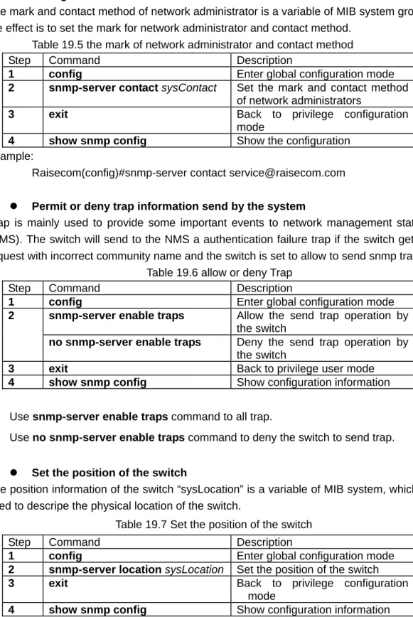
19. SNMP configuration ... 68
19.1. SNMP protocol introduction ... 68
19.2. SNMP configuration ... 68
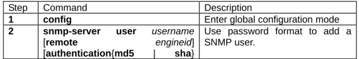
19.2.1. Configure SNMP user... 68
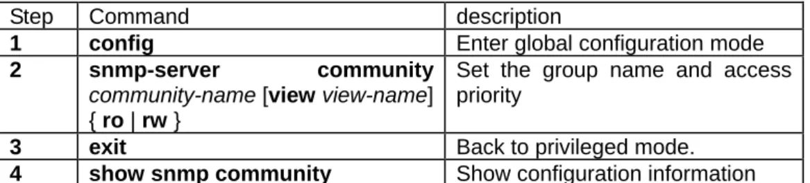
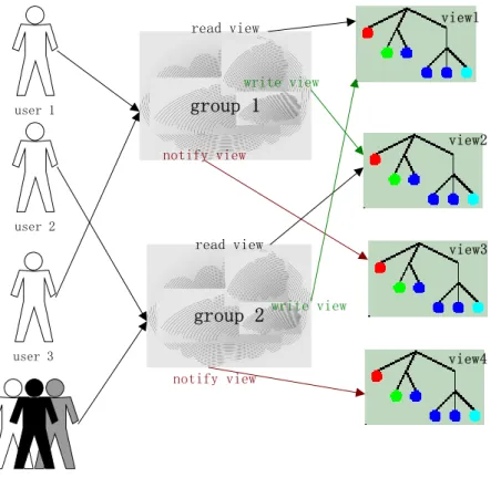
19.2.2. Access priority configuration... 69
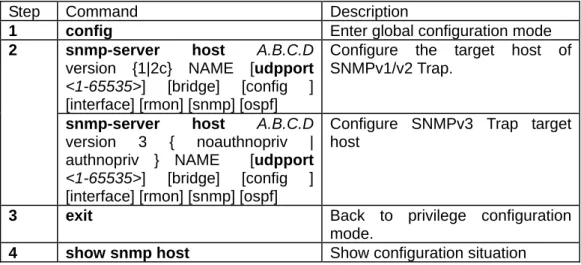
19.2.3. TRAP configuration ... 72
19.3. Other configuration ... 73
19.4. Show SNMP configuration information ... 74
20. Cluster management... 75
20.1. Cluster introduction ... 75
20.2. Cluster management configuration list... 76
20.2.1. Globally enable RNDP... 76
20.2.2. RNDP port enable ... 77
20.2.3. RTDP enable ... 77
20.2.4. RTDP collection range... 78
20.2.5. Enable and disable of cluster management... 78
20.2.6. Automaticly active function enable ... 78
20.2.7. add and active cluster member... 79
20.2.8. delete cluster member ... 80
20.2.9. Cluster member suspend ... 81
20.2.10. add and suspend all the candidate member ... 81
20.2.11. Cluster member remote management ... 82
20.3. Monitoring and maintenance... 83
20.3.1. RNDP neighbour information display... 83
20.3.2. RTDP device information display:... 83
20.3.3. Display cluster management informaiton... 84
21. System log configuration... 85
21.1. System log introduction... 85
21.2. System log configuration... 85
21.2.1. The enable and disable for system log ... 85
21.2.2. The time mark setting of log information... 86
21.2.3. log rate configuration ... 86
21.2.4. Log information output configuration ... 86
21.2.5. show log configuration ... 87
22. System clock... 88
22.1. System clock... 88
22.1.2. Manually configure system time ... 88
22.1.3. Set summer time ... 89
23. Loopback detection... 91
23.1. Detection method... 91
23.2. loopback detection function configuration ... 91
24. Schedule-list configuration ... 93
24.1. The setting for schedule-list ... 93
24.2. Schedule-list configuration based on command line ... 93
25. Trouble shooting command... 94
25.1. trouble shooting ... 94
25.1.1. Memory usage information ... 94
25.1.2. Port driving pool usage information ... 94
25.1.3. Process and stack status... 95
25.1.4. UP/DOWN statistical information... 96
25.1.5. Information gathering for trouble shooting ... 97
26. VLAN Configuration ... 98
26.1. VLAN introduction ... 98
26.2 VLAN member port mode ... 99
26.2. VLAN configuration list... 99
26.2.1. Create and delete VLAN... 99
26.2.2. VLAN name settings:... 100
26.2.3. VLAN active status settings ... 100
26.2.4. VLAN mode of port and relevant attributes setting ... 101
26.2.5. Monitor and maintenance ... 106
27. Port Statistics ... 107
27.1. Introduction to port statistics ... 107
27.2. Port statistics configuration ... 107
27.3. Monitor and maintenance ... 107
28. ACL and network security setting... 109
28.1. ACL introduction ... 109
28.2. configure ACL ... 109
28.3. use ACL at second layer physical interface or on the VLAN ...117
28.4. Use ACL on third layer interface ...119
29. QoS Configuration ... 121
29.1. QoS Introduction... 121
29.1.1. Classification ... 123
29.1.2. Policying and marking ... 124
29.1.3. Mapping table ... 125
29.1.4. Queueing and scheduling ... 125
29.2.1. QOS Default setting... 126
29.2.2. QOS enable and disable ... 127
29.2.3. Configure QoS trust status and CoS default value ... 127
29.2.4. Configure QoS mapping table: ... 128
29.2.5. Configure the class map of QoS... 135
29.2.6. configure QoS policy map ... 137
29.2.7. configure QoS flow classification ... 137
29.2.8. Apply the policy on the port ... 141
29.2.9. Set the scheduling mode for egress queue ... 141
29.3. QOS monitor and maintenance ... 142
29.3.1. Show QOS enable information ... 143
29.3.2. show QOS policer information ... 143
29.3.3. show QOS map information... 143
29.3.4. show QOS queue information... 144
29.3.5. show QOS port information ... 145
29.3.6. show QOS class-map information ... 146
29.3.7. Show QOS policy-map information... 146
29.3.8. Show QOS policy-map application information... 147
29.4. QOS trouble shooting: ... 147
29.5. QOS command reference ... 147
30. MVR configuration ... 150
30.1. About MVR ... 150
30.2. IGMP filter introduction ... 151
30.3. Configure MVR function... 151
30.3.1. MVR default configuration ... 151
30.3.2. MVR global configuration ... 151
30.3.3. Configure MVR port information ... 153
30.3.4. MVR monitor and maintenance ... 154
30.4. Configure IGMP filter table... 155
30.4.1. IGMP filter default configuration ... 156
30.4.2. profile configuration ... 156
30.4.3. Apply IGMP profile... 157
30.4.4. The maximum port number configuration ... 158
30.4.5. The monitor and maintenance of IGMP filtering ... 159
30.5. Typecial configuration for MVR application ... 160
30.6. Trouble shooting of MVR and IGMP filtering... 161
Raisecom Technology Co., Ltd
1. Overview
1.1. Audience
The Raisecom series Switch Software Configuration Guide is for the network manager responsible for configuring the ISCOM series switches. This guide provides information about configuring and troubleshooting a switch or switch clusters. It includes descriptions of the management interface options and the features supported by the switch software.
1.2. Abbreviation
GARP: Generic Attribute Registration Protocol GVRP: GARP VLAN Registration Protocol GMRP GARP Multicast Registration Protocol LACP: Link Aggregation Control Protocol STP: Spanning Tree Protocol
VLAN: Virtual LAN
DHCP: Dynamic Host Configuration Protocol BOOTP: BOOTSTRAP PROTOCOL
IGMP Internet Group Management Protocol QoS: Quality of Service
CoS: Class of Service ToS: Type of Service
DSCP: Differentiated Services Code Point WRR: Weighted Round Robin
CIDR Classless Inter Domain Routing EGP: Exterior Gateway Protocol
ICMP: Internet Control Message Protocol IGP: Interior Gateway Protocol
InARP: Inverse ARP MBZ: Must be Zero
MIB: Management Information Base OSPF: Open Shortest Path First PDU: Protocol Data Unit
RIP: Routing Information Protocol MVR: Multicast VLAN registration
1.3. Reference
Raisecom Technology Co., Ltd
2. Summary
2.1. layter-2 static management and hardware assistant
function
1 Port mirror(any port to any port);
2 Storm-control, provide the control for broadcast, multicast and DLF frame control 3 The static management for the ARL table of the switch (capacity is 8K).
2.2. Stardard layer 2 protocol
1 802.1w fast spanning tree protocol; 2 802.1D/W,802.1Q;
3 IGMP Snooping(multicast address:256);
2.3. Management function
1 Support cluster management function;
2 Support SNMP(RFC1157),SNMP V2 and SNMPV3; 3 Support CONSOLE management;
4 Support remote management by TELNET;
5 Support automaticly control function, that is it can download configuration file automaticly from network configuration server, finish the configuration.
6 Support rmon 1,2,3,9 group;
2.4. DHCP
Configure DHCP SERVER and DHCP RELAY function (three layer support) after authentication.
2.5. Bandwidth management
Bandwidth management based on the port.
2.6. Layer 3 function
1 Support static route;
2 8k route table as the maximum;
Raisecom Technology Co., Ltd
3. How to use command-line
3.1. Environment
Software requirement: ROS 3.0.
3.2. Command line mode
Mode Mode description Access Prompt
User EXEC To connect the remote device, change terminal settings on a temporary basis, perform basic tests, and display system information.
Login Raisecom>
Privileged EXEC
In this mode, user can configure the basic information of a switch.
From User EXEC mode, type enable and password
Raisecom#
Global configuration mode
Use this command to configure parameters that apply to the whole switch.
From Privileged EXEC mode type config. Raisecom(config)# Physical interface configuration mode. Configure parameters of physical Ethernet interface. From global configuration mode mode type interface port portid command. Raisecom(config-port)# Physical interface range configuration mode In this mode, configure parameters of more than one Ethernet physical interface.
From global configuration
mode mode type interface range port-list command. Raisecom(config-range)# Layer-3 interface configuration mode. Configure the L3 interface parameter in this mode. Under global configuration mode, type interface ip id command. Raisecom(config-ip)# VLAN configuration mode Configure or modify VLAN parameters for VLANs Under global configuration
mode, type Vlan vlan_id
command
Class Map configuration mode
Config parameters of particular data flows in this mode.
From global configuration mode mode, type class-map class-map-name [match-all | match-any ] command. Raisecom(config-cmap)# Policy Map configuration mode
Config the data flow of class-map defined encapsulation and classification. From global configuration mode mode, type policy-map policy-map-name command. Raisecom(config-pmap)# Traffic classification config mode
Config the data flow under this mode.
From policy map exec mode, type class-map class-name command. Raisecom(config-pmap-c)# Cluster configuration mode
Config the cluster under this mode.
From global configuration mode mode, type cluster command. Raisecom(config-cluster)# ACL config mode
Config ACL filtering table From global configuration mode mode, type access-list-map <0-399> {permit | deny} command. Raisecom(config-aclmap)#
3.3. Get help
Command Functional description
help Get a short system help both in English and in Chinese.
abbreviated-command-entry? Get a list for all the available commands that match a particular string
prefix(abbreviated-command-entry). For example: ISCOM2826> en?
english enable
abbreviated-command-entry<Tab> Makeup a incompleted command. For example.
Raisecom#show ser<Tab> Raisecom#show service
? List all the commands under this mode. For example
Raisecom#?
command ? List all the key words and options for particular command with a short help information for it. Raisecom#show ?
3.4. Use history commands
Switch will record 20 history commands by default. User can use
command count.
Use command history to show history command.
3.5. Editing properties
up arrow: last entered command down arrow: next entered command left arrow: move a character left right arrow: move a character right
backspace: delete a character in front of the cursor Ctrl+d: delete a character at the cursor
Ctrl+a: move the cursor to the beginning of the command line Ctrl+e: move the cursor to the end of the command line Ctrl+k: delete all the characters on the right side the cursor Ctrl+w: delete all the characters on the left side of the cursor Ctrl+u: delete the row all
4. System command configuration
This chapter introduces the basic system configuration and user management.
4.1. Basic system command and configuration
chinese show help information of the command in Chinese english show help information of the command in English clear clear the information on the screen
list Use this command to show all commands under the mode in the form of list.
clock set: Change system time.
4.2. Configuration files and boot files management
4.2.1. configuration
files.
¾ Default name for current system stored file is: startup_config.conf;
¾ Use write command to save configuration information to the flash file systems, when the system is restarted, the configuration information will be reloaded automatically.
¾ Use erase command to delete files.
¾ With upload and download commands, user can upload configuration file startup_config.conf to the server, or download new configuration information from the server by TFTP protocol or by FTP protocol.
¾ Use show startup_config command to show saved config information.
¾ Use show runnging_config command to show current system configuration information.
4.2.2. Startup
files
¾ That is program file, the program file name for current system is system_boot.z;
¾ User can use TFTP protocol or FTP protocol to upload files to the server or download program files from the server.
¾ User dir command to check flash system files.
¾ Use show version command to check software version information.
4.3. User management
The system has a default username raisecom and the password raisecom; Add a new user, the steps are as follows:
Step Command Description
1 user USERNAME password { no-encryption | md5 }
PASSWORD
·USERNAME Username; ·Password password key word; ·{ no-encryption | md5} use
no-encryptionor md5 encryption password.
·PASSWORD password information; 2 user USERNAME privilege
<1-15>
·USERNAME username; ·Privilege privilege key word; ·<1-15> user privilege.
3 Write Save configuration information
Raisecom Technology Co., Ltd
5. Mirror function configuration
This chapter includes the following parts:
Enable or disable mirror function.
Configure the monitor ports
Configure the source port
The mirror function is that mirror the traffic of one port to a specified port according to configured rules. Administrator can use this function to analyze network traffic. It allows many mirror ports at the same time but only one monitor port. Mirror function is not available in default situation.
5.1. Enable or disable mirror function
All the configuration are enabled after the mirror function is enabled. Command Description config Access global configuration mode mirror { enable | disable } Enable/disable mirror function.
exit Exist from global configuration mode to
privileged EXEC
show mirror Show mirror configuration onformation.
5.2. Configure the monitor port
The traffic of source port will be copied to the monitor port, so that network administrators can analyze the network. Port 1 is monitor port by default, the source port and the monitor can not be the same port.
Command Description config Access global configuration mode. mirror monitor-port
port_number
Set the monitor port.
port_number is physical port number,range is 1-26.
exit Exist from global configuration mode and enter privileged EXEC. A B C D E F G H SELECTED ON-LINE 2 3 4 25 … Mirror the data of port 4 to port 25
show mirror Show mirror configuration Use no mirror monitor-port command to recover to default settings.
5.3. configure the source port.
When the mirror function is enabled, the egress/ingress packets of source port will be copied to the monitor port. Users should configure the mirror rules when configure the source port: both, ingress and/or egress. The port cannot be set to source port if it has been set to monitor port.
(1) Mirror both the ingress and egress packets.
Command Description config Enter global configuration mode. mirror source-port-list both
port-list
Set the source port and the mirror rule is that copy both the ingress and egress packets .
port-list is the physical port list, range is 1-26, comma “,” and “-“ to set multiple port.
exit Exist from global configuration mode to
privileged EXEC
show mirror Show mirror setting.
(2)mirror the ingress message,,mirror rule is ingress.
Command Description config Enter global configuration mode mirror source-port-list ingress
port-list
Set the source port and the mirror rule is that copy the ingress packets.
Port-list is the physical port list, range is 1-26, use “,” and “_” for multiple input.
exit Exist from global configuration mode to
privileged EXEC
show mirror Show mirror configuration.
(3)mirror the egress message, mirror rule is egress
Command Description config Enter global configuration mode mirror source-port-list egress
port-list
Set the source port and the mirror rule is that copy the egress packets.
Port-list is physical port list, range is 1-26, can use “,” and “-“ for multiple input.
exit Exist from global configuration mode to
privileged EXEC
Show mirror Show mirror configuration.
(4)configure the mirror for different direction, the mirror rule is ingress or egress. Command Description
config Enter global configuration mode. mirror source-port-list ingress
port-list egressprot-list
Set the source port and the mirror rule is that copy some ports’ ingress packets and some ports’ egress packets.
Port-list is the physical port list, range is 1-26, use “,”and”-“ for multiple input.
exit Exist from global configuration mode to
privileged EXEC
show mirror Show mirror configuration.
Delete the mirror configuration through command no mirror source-port-list
Use global configuration command no mirror all to delete all the mirror setting, use command show mirror to show all the mirror settings.
5.4. Example
Set port 26 as monitor port, ingress packets of port 5-8 and egress packets of port 7-12 will be monitorred.
iscom2826#config
iscom2826(config)#mirror enable
iscom2826(config)#mirror monitor-port 26
iscom2826(config)#mirror source-port-list ingress 5-8 egress 7-12 iscom2826(config)#exit
iscom2826#show mirror Mirror: Enable
Monitor port: 26
---the ingress mirror rule--- Mirrored ports: 5-8
---the egress mirror rule--- Mirrored ports: 7-12
Raisecom Technology Co., Ltd
6. Port rate limiting configuration
This chapter describes the port rate limiting on Raisecom ISCOM series switche.
6.1. Configure the port bandwidth
(1)configure the rate limiting and the burst of ingress traffic.
Command Description config Enter global configuration mode rate-limit port-list {all | port-list}
ingress rate [burst]
Configure the rate limiting and the burst of ingress traffic.
port-list physical port number,range is 1-26,use “,” and “-“ for multiple input.
rate stands for the bandwidth value, unit is kbps,range is 1-1048576. The real value is not the same with the configured value.
burst: unit is KBps, the available value is 1-512.
The real value can be different with the configured value.
ingress is the input direction.
exit Exist from global configuration mode and enter privileged user exec.
show rate-limit port-list [port-lis]
Show the rate limiting of the port
port-list physical port number,range is 1-26,use “,” and “-“ for multiple ports configuration. (2)configure bandwidth and the burst for egress fraffic.
Command Description config Enter global configuration mode. rate-limit port-list {all | port-list}
egress rate [burst]
Configure the rate limiting and the burst of egress traffic.
port-list physical port,range is 1-26,can use“,”and“-”for multiple port input.
Rate is the set bandwidth value, unit is kbps,the scale is 1-1048576, The real value can be different with the set value.
burst: unit is KBps, the available value is 1-512.
The real value can be different with the set value.
egress is the input direction.
exit Exist from global configuration mode and enter privileged user mode.
show rate-limit port-list [port-lis]
Show the bandwidth limitation for the port.
port-list: the same with above
Use global configuration command no rate-limit port-list {all | port-lis} {both | ingress | egress} to delete the rate limiting configuration.
6.2. Example
Set the ingress bandwidth of port 5-7 to 1000Kbps, burst is 64kbps, port 1,9 egress bandwidth is 4096kbps, burst is 70kbps.
Raisecom#config
ISCOM2826(config)# rate-limit port-list 5-7 ingress 1000 64 Set successfully
Actual ingress burst of FE port: 64
ISCOM2826(config)# rate-limit port-list 1,9 egress 4096 60 Set successfully
Actual Egress rate of FE port: 5000 Actual egress burst of FE port: 64 ISCOM2826(config)#exit
Raisecom# show rate-limit port-list 1,5-7,9 I-Rate: Ingress Rate
I-Burst: Ingress Burst E-Rate: Egress Rate E-Burst: Egress Burst
Port I-Rate(Kbps) I-Burst(KBps) E-Rate(Kbps) E-Burst(KBps) --- 1 0 0 5000 64 5 1000 64 0 0 6 1000 64 0 0 7 1000 64 0 0 9 0 0 5000 64
Raisecom Technology Co., Ltd
7. MAC address table manangement
This chapter includes following parts.
Configure the aging time of MAC address.
Enable/disable the MAC address learning function.
Configure the static MAC address.
Configure static MAC address.
Search MAC address.
Delete MAC address table entries.
Show MAC address.
7.1. Configure the aging time of MAC address
The MAC address table contains address information that the switch uses to forward traffic between ports. All MAC addresses in the address table are associated with one or more ports. The address table includes these types of addresses: Dynamic address: a source MAC address that the switch learns and then ages when it is not in use; Static address: a manually entered unicast or multicast address that does not age and that is not lost when the switch resets. The address table lists the address, the associated VLAN ID, port number associated with the address and the flags.
Command Description config Enter global configuration mode. mac-address-table aging-time
{ 0 | time }
Set the aging time for MAC address. 0 stands for MAC address aging is disabled Time is the target MAC address aging time, unit is second, range is 3-765, and default value is 300.
exit Exist from global configuration mode and enter privileged user exec.
show mac aging-time Show MAC address aging time.
Recover the default value of aging time, and use no mac-address-table aging-time. For example:
set the aging time to 500 seconds. Raisecom#config
Raisecom(config)#mac-address-table aging-time 500 Raisecom(config)#exit
Raisecom#show mac aging-time Aging time: 500 seconds.
Disable MAC address aging Raisecom#config
Raisecom(config)#mac-address-table aging-time 0 Raisecom(config)#exit
Raisecom#show mac aging-time Auto-aging is disable!
7.2. Confiugre static MAC address
Static address is a manually entered unicast or multicast address that does not age and that is not lost when the switch resets. There is no static MAC address by default.
Command Description config Enter global configuration mode. mac-address-table static
HHHH.HHHH.HHHH vlan vlan_id port port-number
Set the static MAC address.
HHHH.HHHH.HHHH is the static MAC address which will be set, format is hexdecimal string,
dotted notation for every four characters. Vlan_id range is 1-4094.
port_number is the physical port number, range is 1-26.
exit Exist from global configuration mode and enter privileged user exec.
show mac-address-table static [ port port-number | vlan
vlan_id ]
Show (port or VLAN) static address.
port_number is physical port, range is 1-26.
vlan_id: range is 1-4094.
Delete static MAC address and use no mac-address-table static HHHH.HHHH.HHHH vlan vlan_id port port-number.
For example: set the static MAC address 1234.1234.1234, belongs to VLAN 1, port 10.
Raisecom#config
Raisecom(config)# mac-address-table static unicast 1234.1234.1234 vlan 1 port 10 Raisecom(config)#exit
Raisecom#show mac-address-table static Port Vlan Static Mac Addrress ---
10 1 1234.1234.1234
7.3. Enable/disable the MAC address learning function
The MAC address learning function can be enabled/disabled based on per port: Command Description
config Enter global configuration mode. mac-address-table
learning {enable | disable} port-list {all | {1-26}}
Enable or disable the MAC address learning function of physical port.
enable enable MAC address learning function function.
disable disable MAC address learning function function.
port_number physical port number, range is 1-26. exit Withdraw global configuration mode and enter
privilege configuration mode. show interface port
[port-number]
Show port status.
port_number physical port,range is 1-26. For example:Deny MAC address learning function of port 10.
Raisecom#config
Raisecom(config)#exit
Raisecom#show interface port 10 R: Receive Direction
S: Send Direction
Port Admin Operate Speed/Duplex Flowcontrol(R/S) Mac-learning ---
10 enable down auto off/off disable
7.4. Delete MAC address table.
Clear layer-2 MAC address table entries of the switch, includes static and dynamicl MAC address.
Command Description clear mac-address-table {all |
dynamic | static}
all: delete all the layer 2 MAC address. dynamic: only delete dynamic MAC address static: only delete static MAC address. For example:Delete dynamic MAC address.
Raisecom#clear mac-address-table dynamic
7.5. Show MAC address table.
show,check the layer 2 MAC address information for the switch.
Command Description show mac-address-table
l2-address [ {count [{port
port-number | vlan vlan_id} ] | port port-number | vlan
vlan_id}]
Show the MAC address information for the switch.
Count calculate the number of MAC address
port_number physical port, range is 1-26.
vlan_id rane is 1-4094. For example:show the MAC address on port 1.
Raisecom#show mac-address-table l2-address port 1 MAC address port VLAN
0001.0297.60F5 1 1 0001.0340.6A0B 1 1 0001.0340.6B23 1 1 0002.1EE6.5157 1 1 0002.1EE6.5643 1 1 0002.1EE6.5820 1 1 0002.1EF2.200F 1 1 0002.1EF7.6271 1 1 . . ……… For example:
Show the total number of all the studied MAC address on port 1. Raisecom#show mac-address-table l2-address count port 1
MAC address count of port 1: 97
7.6. Search particular MAC address.
Search the MAC address information of the switch.
Command Description search mac-address
HHHH.HHHH.HHHH
Search MAC address
HHHH.HHHH.HHHH: the MAC address which will be searched, format is hexdecial, dotted notation for every four characters.
For example:add static MAC address 1234.1234.1234,and the MAC address status in the switch.
Raisecom#config
Raisecom(config)#mac-address-table static 1234.1234.1234 vlan 1 port 10 Raisecom(config)#exit
Raisecom#search mac-address 1234.1234.1234
MAC address port VLAN Sysbol ---
Raisecom Technology Co., Ltd
8. Physical interface configuration
This chapter includes following parts:
Configure the speed and duplex mode
Configure the 802.3x flow traffic function of the port.
Open or shutdown the port.
8.1. Configure the speed and duplex mode of the port.
GE port will always be in 1000Mbps and full duplex mode. When enable auto negociation function, the duplex mode (speed) will be set according to auto negotication result. In default situation, auto negociation is enabled.
Command Description config Enter global configuration mode. interface port port-number
interface range port-list
Enter Ethernet physical interface configuration mode or physical port range configuration mode.
port_numberis the phycial port, range is 1-26. port-list range is 1-26, use “,” and “-“ for multiple input.
speed {auto | 10| 100 |1000 } duplex { full | half }
Set the speed and duplex mode of the port. auto: represents that both the speed and duplex are set to autonegociation.
10: represents that the speed is set to 10Mbps. 100:represents that the speed is set to 100Mbps.
1000: set kilomega port.
full: set the duplex mode to full duplex. half: set the duplex mode to half duplex.
exit Exist from Ethernet physical port and enter global configuration mode.
exit Withdraw global configuration mode and enter privileged user exec.
show interface port
port-number
Show the status for the port.
port_number physical port, range is 1-26. Use Ethernet physical port configuration command speed auto to set the speed and duplex mode in auto negociation mode.
For example: set the speed of port 15 to 10Mbps, duplex mode is full duplex. Raisecom#config
ISCOM2826(config)#interface port 15 ISCOM2826(config-port)#speed 10 ISCOM2826(config-port)# duplex full ISCOM2826(config-port)#exit
ISCOM2826(config)#exit
Raisecom#show interface port 15
R: Receive Direction S: Send Direction
Port Admin Operate Speed/Duplex Flowcontrol(R/S) Mac-learning ---
8.2. Configure the 802.3x flow control function of the port
The flow control function for both ingress and egress traffic can be differently. In default situation, flow control function is disabled for both direction.
Command Description config Enter global configuration mode interface port port-number
interface range port-list
Enter Ethernet physical interface configuration mode or range configuration mode.
port_number physical ports,range is 1-26.
port-list,range is 1-26,use “,” and “-“ for multiple ports.
flowcontrol {receive|send}{ on | off }
Enable/disable the flow control function of ingress and egress traffic.
Send represents the traffic control function at egress direction.
Receive represents the traffic control function at ingress direction.
on enabe the traffic control function for the port.
off disable the traffic control function for the port.
exit Exist from the physical interface configuration mode and enter global configuration mode. exit Exist from global configuration mode and enter
privileged user exec. show interface port
port-number
Show the traffic control of the port.
port_number physical port number,range is 1-26.
For example:Set the traffic control for port 10. Raisecom#config
ISCOM2826(config)# interface port 10
ISCOM2826(config-port)#flowcontrol receive on ISCOM2826(config-port)#exit
ISCOM2826(config)#exit
Raisecom#show interface port 10 R: Receive Direction
S: Send Direction
Port Admin Operate Speed/Duplex Flowcontrol(R/S) Mac-learning ---
10 enable down auto on/off enable
8.3. Open/shutdown the port
Ethernet port can be open or shutdown flexibly according to user requirements: Command Description config Enter global configuration mode. interface port port-number
interface range port-list
Enter Ethernet physical port configuration mode or range configuration mode.
port_number physical port number, range is 1-26.
port-list port list,range is 1-26,can use”,”and “-“ for multiple setting.
shutdown close physical port. no shutdown start physical port.
exit Exist from physical port configuration mode and enter global configuration mode.
exit Exist from global configuration mode and enter privileged user exec.
show interface port
port-number
Show port status.
port_number physical port number,range is 1-26.
For example: shutdown port 20. Raisecom#config
ISCOM2826(config)# interface port 20 ISCOM2826(config-port)#shut down ISCOM2826(config-port)#exit
ISCOM2826(config)#exit
Raisecom#show interface port 20
R: Receive Direction S: Send Direction
Port Admin Operate Speed/Duplex Flowcontrol(R/S) Mac-learning ---
Raisecom Technology Co., Ltd
9. Strom control
A packet storm occurs when a large number of broadcast, unicast, or multicast packets are received on a port. Forwarding these packets can cause the network to slow down or to time out. Storm control is configured for the switch as a whole but operates on a per-port basis. By default, storm control is enabled.
Storm control uses thresholds to limit the forwarding of broadcast, unicast, or multicast packets. The thresholds can either be expressed as a percentage of the total available bandwidth that can be used by the broadcast, multicast, or unicast traffic (x% of the port’s available rate), or as the rate at which the interface receives multicast, broadcast, or unicast traffic (PPS: packet per sencond).
9.1. Enable the control function
This function is used to enable/disable storm control function on ports. Command Description config Enter global configuration mode storm-control {broadcast |
multicast | dlf | all} {enable | disable}
Enable/disable the storm control function, and configure the packet limitation for broadcast packet, multicast packet and DLF packet. Broadcast: broadcast packet.
multicast: multicast packet.
DLF: d
estination lookup failure unicast
packet.
all: broadcast,multicast and dlf unicast.
exit Exist from global configuration mode and enter privileged user exec.
show storm-control Show storm control status. Example: shutdown the storm control of broadcast packet. Raisecom#config
ISCOM2826(config)# storm-control broadcast disable ISCOM2826(config)#exit
Raisecom#show storm-control Broadcast: Disable
Multicast: Enable
Unicast destination lookup failed(DLF): Enable Threshold: 1024 pps
9.2. Threshold of strom control
Configure the threshold of storm control. Unit is pps (packet per second). Command Description config Enter global configuration mode. storm-control pps value Set the threshold of storm control.
Threshold of storm-control packet. Range is 0-262143.
privileged user exec.
show storm-control Show the status of storm control Example:set the threshold of storm control to 2000 packet per second. Raisecom#config ISCOM2826(config)# storm-control pps 2000 ISCOM2826(config)#exit Raisecom#show storm-control Broadcast: Disable Multicast: Enable
Unicast destination lookup failed(DLF): Enable Threshold: 2000 pps
10. Shared
VLAN
In Shared VLAN Learning (SVL), the switch makes use of address information learnt across a number of VLANs in making forwarding decisions in connection with other VLANs. In Independent VLAN Learning (IVL), the switch makes use of address information learnt in one VLAN only and does not use this information in making forwarding decisions with any other VLAN.
In SVL, all VLAN share the same learnt MAC address information, regardless of which VLAN the information was learnt in. In IVL, each VLAN makes use only of MAC address information learnt within that VLAN.
10.1. Enable SVL
Command Description config Enter global configuration mode svl { enable | disable } Enable/disable SVL function.
exit Exist from global configuration mode and enter privileged user exec.
show svl Show SVL status.
Example: start SVL mode. Raisecom # config
ISCOM2826 (config)# svl enable ISCOM2826 (config)# exit Raisecom # show svl SVL: Enable
10.2. Configure SVL of port
MAC address learned by that port will be available for all the other VLAN. Command Description config Enter global configuration mode. interface port <1-26> Enter port configuration mode switchport svl vlanlist
{1-4094}
Set SVL of the port.
end Exist from port configuration mode and enter privileged user exec.
show switchport [<1-26>] svl vlanlist
Show the port and VLAN list.
For example:Set the shard VLAN of port 1 to 1-4. Raisecom#config
ISCOM2826(config)#interface port 1
ISCOM2826(config-port)# switchport svl vlanlist 1-4 ISCOM2826(config-port)#exit
ISCOM2826(config)#exit
Raisecom# show switchport 1 svl vlanlist Port SVL VLAN list
--- 1 1-4
10.3. Configure SVL default VLAN
If there is no SVL VLAN list configuration of a port, MAC address table is shared with SVL default VLAN. The default SVL VLAN configuration is as follows:
Command Description config Enter global configuration mode svl default vlan <1-4094> Set SVL default VLAN
exit Withdraw global configuration mode and enter privileged user mode.
show svl default vlan Show SVL default VLAN. Example:Set VLAN 3 as SVL default VLAN.
Raisecom # config
ISCOM2826 (config)# svl default vlan 3 ISCOM2826 (config)# exit
Raisecom # show svl default vlan SVL default vlan: 3
11. Packet transparent transmission
11.1. Overview
There are some kinds of layer-2 packets need to be transparently transmitted, including: BPDU, Dot1x, LACP, GARP, GMRP and GVRP.
11.2. Configure packet transparent transmission
Configure the pass through port and the type of protocol packet that needed to transmit transparently. The port that receive the packet do not pass through any more.
Command Description config Enter global configuration mode relay {bpdu | dot1x | lacp | garp |
gmrp | gvrp | all} port-list
port-list
Set the transmission port of specified protocol packet
Packet types:bpdu,dot1x,lacp,garp,gmrp,gvrp
port-list physical port list, use “,” and “-“ for multiple setting, range is 1-26.
exit Withdraw global configuration mode and enter privileged use mode.
show relay port-list Show the configuration of transmission port.
Cancel the transparent transmission of a port: use command no relay {bpdu | dot1x | lacp | garp | gmrp | gvrp | all} port-list port-list.
Example: let port 1-4 transmit BPDU packet transparently, 3-6 transmit Dotlx packet transparently.
iscom2826#config
iscom2826(config)# relay bpdu port-list 1-4 Set forwarding ports successfully.
iscom2826(config)# relay dot1x port-list 3-6 Set forwarding ports successfully.
iscom2826(config)#exit
iscom2826# show relay port-list Type Ports --- BPDU 1-4 Dot1x 3-6 LACP -- GARP -- GMRP -- GVRP --
11.3. Forward DLF packets
Generally speaking, the DLF unicast packet will be dropped locally. But for some users’ requirements, DLF packets need to be broadcasted sometimes. DLF packets forwarding is disabled by default. The configuration steps are as follows:
config Enter global configuration mode. dlf-forwarding {enable |
disable}
Whether to broadcast DLF message or not. Enable: enable broadcast.
Disable: disable broadcast.
exit Withdraw global configuration mode and enter privileged user mode.
show dlf-forwarding Show DLF transmission configuration. Example: forward DLF packets.
iscom2826#config
iscom2826(config)# dlf-forwarding enable SUCCESS !
iscom2826(config)#exit
iscom2826# show dlf-forwarding DLF-forwarding: Enable
Raisecom Technology Co., Ltd
12. The layer-3 interface configuration
Layer-3 interface configuration provides a virtual interface for management, users can configure IP address for different VLANs. Use ip address command to configure the interface IP address and specify associate VLAN ID and then create a layer-3 interface, use no ip address command to delete it. Refer chaper 13 for VLAN configuration ISCOM2826 support 15 virtual layer-3 interface, each interface corresponding to a static VLAN ID. One static VLAN can only associate with one layer-3 interface.
Following is the procedure for creating three layer interface and IP configuration:
Step Command description
1 config Enter global configuration mode.
2 interface ip <0-14> Enter Ethernet three layer interface configuration mode.
3 ip address ip-address [ip-mask] vlan-id
Set the IP address of three layer interface and associated static VLAN ID.
4 exit Exist to global configuration mode.
5 exit Exist to privileged user exec.
6 show interface ip Show layer-3 configuration information
13. Link Aggregation Control Protocol
13.1. About link aggregation control protocol (LACP)
Link aggregation control protocol allows facilitate the automatic creation of Ethernet channel by exchanging packets between Ethernet interfaces. LACP is defined in IEEE802.3AD and can dynamically group similarly configured interfaces into a single logical link.
This chapter describes the following parts:
Enable or disable trunk function
Add or delete trunk group
Set the trunk-sharing mode for all the trunks.
13.2. Command description
13.2.1. Enable or disable trunk LACP function
Disable or enable the trunk (LACP) function:
Step Command Description
1 config Enter global configuration mode.
2 trunk {enable|disable} Enable or disable trunk function Example:
Raisecom#config
Raisecom(config)#trunk disable Raisecom(config)#exit
13.2.2. Add or delete trunk group
Interfaces in one trunk group will act as a single logical link. User can add or delete trunk group based on following steps.
Step Command Description
1 config Enter global configuration mode.
2 trunk group trunk-group-id portlist
Set trunk group.
Example:
Create trunk group 3, including port 1,5,6,7. Raisecom#config
Raisecom(config)#trunk-group 3,1, 5-7 Raisecom(config)#exit
13.2.3. Set load sharing mode
Interfaces in one trunk group will act as a single logical link, and the load sharing mode decides how the interfaces in one trunk group share the loads.
There are 6 kinds of load sharing mode:
y smac choose the forwarding port based on source MAC address.
y dmac choose the forwarding port based on destrination MAC address.
y sxordmac select forwarding port based on logical “or” calculation of source and destination MAC address.
y sip choose forwarding port based on source IP address.
y sxordip select forwarding port based on logical “or” calculation of source and destination IP address.
step command description
1 config Enter global configuration mode
2 trunk loading-sharing mode {smac | dmac | sxordmac | sip | dip | sxordip}
Set the load sharing mode for allthe trunk.
Example: Based on source MAC address to set the load-sharing mode for all the trunks to choose the transmission port.
Raisecom#config
Raisecom(config)#trunk loading-sharing mode smac
13.3. Maintenance
User can use show command to check associated configuration of the trunk. Command Description show trunk Whether to start the trunk,trunk load sharing
mode, ports of all the trunk group mumber and current effective ports of the mumber. Use show trunk command to display trunk information, trunk load sharing mode, ports of all the trunk group member and current effective ports of the member.
Current effective ports are the port which are forwarding packets: Raisecom#show trunk
Trunk: Enable
Loading sharing mode: SXORDMAC Loading sharing ticket algorithm: --
Trunk Group Member Ports Efficient Ports ---
Raisecom Technology Co., Ltd
14. RSTP
configuration
This chapter introduces how to config RSTP on the switch, including following contents:
About RSTP
RSTP configuration list
Step by step introduction
Maintenance
14.1. About RSTP
The RSTP takes advantage of point-to-point wiring and provides rapid convergence of the spanning tree. Reconfiguration of the spanning tree can occur in less than 1 second (in contrast to 50 seconds with the default settings in the 802.1D spanning tree), which is critical for networks carrying delay-sensitive traffic such as voice and video.
14.2. RSTP configuration list
RSTP globally enable and disable. RSTP system priority configuration.
RSTP Hello Time setting
RSTP Max Age setting
RSTP Forward Delay setting
Switch RSTP running mode
RSTP the setting of maximum send packet by the protocol within hello time
RSTP port enable and disable
RSTP port priority setting
RSTP path cost setting
RSTP edge port setting
RSTP the setting for the type of port link
From current Ethenet port move to RSTP mode
Clear RSTP port statistical information
14.3. Step by step introduction
14.3.1. RSTP globally enable and disable
Default setting: RSTP is enabled. The following steps can disable or enable RSTP.
Step command description
1 config Enter global configuration mode
2 spanning-tree {enable | disalbe}
Enable or disable RSTP
3 exit Back to privileged user mode.
4 show spanning-tree Show spanning tree configuration information.
Following is an example for RSTP disable: Raisecom#config
Raisecom(config)#spanning-tree disable Raisecom(config)#exit
14.3.2. RSTP switch priority setting
The RSTP topology of a network is determined by the following elements:
9 The unique bridge ID (switch system priority and MAC address)
9 The spanning-tree path cost to the root switch
9 The port identifier (port priority and MAC address) associated with each Layer 2 interface
The bridge ID decides whether the switch can be a root switch and combines 8 byte: 2 bytes of switch system priority and 6 bytes of switch MAC address. The smaller bridge ID has higher priority, and the switch which has the smallest bridge ID will be selected as root switch of the network.
The value of system priority much be the multiple of 4096. Change RSTP system priority as following:
Step Command Description
1 config Enter global configuration mode
2 spanning-tree priority
<1-61440>
Set RSTP system priority
3 exit Back to privileged user mode
4 show spanning-tree Show RSTP configuration
situation Set RSTP system priority to 4096:
Raisecom#config
Raisecom(config)#spanning-tree priority 4096 Raisecom(config)#exit
Raisecom#show spanning-tree
14.3.3. RSTP Hello Time setting
Switch sends Bridge Protocol Data Unit (BPDU ) periodically, and the default interval time value is 2 seconds. Users can change the value based on network situation. When system configuration information losses frequently, user can reduce the value to make the STP more stronger.
Change the RSTP hello time as following:
Step Command Description
1 config Enter global configuration mode
2 spanning-tree hello-time <1-10>
Set RSTP的Hello Time
3 exit Back to privileged user mode
4 show spanning-tree Show RSTO configuration
information Set RSTP hello time to 3 seconds:
Raisecom#config
Raisecom(config)#spanning-tree hello-time 3 Raisecom(config)#exit
Raisecom#show spanning-tree
14.3.4. RSTP Max Age setting
The maximum aging time is the number of seconds a switch waits without receiving spanning-tree configuration messages before attempting a reconfiguration. Users use no spannin-tree max-age command to recover the default value.
Change the RSTP Mac age as following steps:
1 config Enter global configuration mode 2 spanning-tree max-age <6-40> Set RSTP Max Age
3 exit Back to privileged use mode
4 show spanning-tree Show RSTP configuration information
Example
Set RSTP Max Age to 6 seconds: Raisecom#config
Raisecom(config)#spanning-tree max-age 6 Raisecom(config)#exit
Raisecom#show spanning-tree
14.3.5. RSTP Forward Delay setting
The forward delay is the number of seconds a port waits before changing from its spanning-tree learning and listening states to the forwarding state. User can use no spanning-tree forward-delay command to recover default value. Change RSTP Forward Delay as following:
Step Command Description
1 config Enter global configuration mode
2 spanning-tree forward-delay <4-30>
Set the forward delay of RSTP
3 exit Back to privileged user mode.
4 show spanning-tree Show RSTP configuration situation.
Example:
Set RSTP Forward Delay to 5 seconds: Raisecom#config
Raisecom(config)#spanning-tree forward-delay 5 Raisecom(config)#exit
Raisecom#show spanning-tree
14.3.6. Switch RSTP running mode
IEEE 802.1w protocol defines two modes: stp mode and rstp compatible mode. Under the STP mode, switch does not execute fast forwarding of designated port and fast changing from designated port to root port. RSTP only send STP BPDU and topology changing notification. The received RST BPDU will be dropped.
Raisecom series switch supports both STP and RSTP mode:
Step Command Description
1 config Enter global configuration mode
2 spanning-tree mode {stp|rstp} Set RSTP running mode.
3 exit Back to privileged user mode.
4 show spanning-tree Show RSTP configuration information.
The configuration of RSTP running mode as following: Set RSTP running mode to RSTP mode:
Raisecom#config
Raisecom(config)#spanning-tree mode rstp Raisecom(config)#exit
14.3.7. the maximum packets sent within hello time.
Use this command to set the BPDU packet transmission limitation of RSTP within hello time. the higher transmit speed is, the more packets can be sent in each time unit.
The following commands configure the maximum packets sent within hello time:
Step Command Description
1 config Enter global configuration mode
2 spanning-tree transit-limit <1-10>
Set the maximum BPDU packet by RSTP protocol within hello time.
3 Exit Back to privileged user mode.
4 show spanning-tree Display RSTO configuration situation.
Set the maximum BPDU packet by RSTP protocol within hello time to 6: Raisecom#config
Raisecom(config)#spanning-tree transit-limit 6 Raisecom(config)#exit
Raisecom#show spanning-tree
14.3.8. RSTP port enable and disable
To control RSTP flexibly, user can disable the RSTP protocol based on per port. It will let those ports do not take part in the STP computing. Use following commands to
enable/disable the RSTP protocol on designated Ethernet port.
Step Command Description
1 Config Enter global configuration mode
2 interface port <1-26> Enter Ethernet physical interface mode.
3 spanning-tree {enable | disalbe}
Set the priority of RSTP port.
4 Exit Back to global configuration mode.
5 Exit Back to privileged user mode
6 show spanning-tree Show RSTP configuration situation
Example:
Shutdown RSTP protocol of port 2: Raisecom#config Raisecom(config)#interface port 2 Raisecom(config-port)#spanning-tree disable Raisecom(config-port)#exit Raisecom(config)#exit Raisecom#show spanning-tree
14.3.9. RSTP port priority setting
If a loop occurs, spanning tree uses the port priority when selecting an interface to put into the forwarding state. You can assign higher priority values (lower numerical values) to interfaces that you want selected first and lower priority values (higher numerical values) that you want selected last. If all interfaces have the same priority value,
spanning tree puts the interface with the lowest interface number in the forwarding state and blocks the other interfaces.
Step Command Description
2 interface port <1-26> Enter Ethernet physical interface mode.
3 spanning-tree priority <0-240> Set RSTP port priority
4 Exit Back to global configuration mode.
5 Exit Back to privileged user mode.
6 show spanning-tree Show RSTP configuration information
Example:
Set the RSTO port priority of physical port 2 to 16: Raisecom#config Raisecom(config)#interface port 2 Raisecom(config-port)#spanning-tree priority 16 Raisecom(config-port)#exit Raisecom(config)#exit Raisecom#show spanning-tree
14.3.10.
The path cost configuration
The spanning-tree path cost default value is derived from the media speed of an interface. If a loop occurs, spanning tree uses cost when selecting an interface to put in the
forwarding state. You can assign lower cost values to interfaces that you want selected first and higher cost values that you want selected last. If all interfaces have the same cost value, spanning tree puts the interface with the lowest interface number in the forwarding state and blocks the other interfaces.
Default path cost of different media speed is:
y 10Mbps is 2000000;
y 100Mbps is 200000;
y 1000Mbps is 20000;
The steps to change RSTP port expense:
Step Command Description
1 Config Enter global configuration mode
2 interface port <1-26> Enter Ethernet physical port mode.
3 spanning-tree path-cost
<0-200000000>
Set RSTP port expense
4 Exit Back to global configuration mode.
5 Exit Back to privileged user mode.
6 show spanning-tree Show RSTP configuration situation.
Set the RSTP port expense of Ethernet physical interface 2 to 1000000. Raisecom#config Raisecom(config)#interface port 2 Raisecom(config-port)#spanning-tree path-cost 1000000 Raisecom(config-port)#exit Raisecom(config)#exit Raisecom#show spanning-tree
14.3.11.
RSTP edge port setting
If you configure a port as edge port on an RSTP switch, the edge port immediately changes to the forwarding state. So please enable it only on ports that connects to a single end station. The steps of how to set the edge ports as following:
Step Command Description
1 Config Enter global configuration mode
2 interface port <1-26> Enter Ethernet physical interface mode.
3 spanning-tree edged-port Set edge port.
4 Exit Exist to global configuration mode.
5 Exit Exist to privileged user mode.
6 show spanning-tree Show RSTP configuration information.
Example:
Set the Ethernet physical port 2 to edge port. Raisecom#config Raisecom(config)#interface port 2 Raisecom(config-port)#spanning-tree edged-port Raisecom(config-port)#exit Raisecom(config)#exit Raisecom#show spanning-tree
14.3.12.
Setting of RSTP port link
If you connect a port to another port through a point-to-point link and the local port becomes a designated port, it negotiates a rapid transition with the other port by using the proposal-agreement handshake to ensure a loop-free topology.
By default The switch determines the link type from the port duplex mode: a full-duplex port is considered to have a point-to-point connection; a half-duplex port is considered to have a shared connection.
Set the link type of RSTP port as following:
Step Command Description
1 Config Enter global configuration mode
2 interface port <1-26> Enter etherent physical interface mode.
3 spanning-tree link-type
{point-to-point | shared}
Set the point-to-point link type
4 Exit Back to global configuration mode
5 Exit Back to privileged user mode.
6 show spanning-tree Show RSTP configuration Example:
Set Ethernet physical interface 2 to point-to-point link. Raisecom#config
Raisecom(config)#interface port 2
Raisecom(config-port)#spanning-tree link-type point-to-point Raisecom(config-port)#exit
Raisecom(config)#exit
Raisecom#show spanning-tree
14.3.13.
Force the urrent Etherent port in RSTP mode
If the network is stable, even though the bridge (which LAN runs STP) is disconnected, the switch which runs RSTP and connects to the bridge is still in STP compatibility mode. Use spanning-tree mcheck command to set mCheck variables and force the port to be in RSTP mode. When the port is in RSTP mode, if it receives new STP packets, the port will be back to STP compatibility mode.
The steps that Ethernet port moves back to port RSTP mode as following:
Step Command Description
1 Config Enter global configuration mode
2 interface port <1-26> Enter Ethernet physical interface mode.
3 spanning-tree mcheck Force the port move back to RSTP mode.
4 Exit Back to global configuration mode.
5 Exit Back to privileged user mode.
6 show spanning-tree Show RSTP configuration mode. Example:
Force physical port 2 move back to RSTP mode. Raisecom#config Raisecom(config)#interface port 2 Raisecom(config-port)#spanning-tree mcheck Raisecom(config-port)#exit Raisecom(config)#exit Raisecom#show spanning-tree
14.3.14.
Clear RSTP port statistical information
RSTP counts the BPDU message quantity for each RSTP port: ingress STP detection message, ingress notification message, ingress RSTP message, egress STP detection message, egress notification message, and egress RSTP message.
Clear RSTP port statistical information:
Step Command description
1 Config Enter global configuration mode.
2 interface port <1-26> Enter etherent interface mode. 3 spanning-tree clear statistics Clear port statistical information.
4 Exit Back to global configuration mode.
5 Exit Back to privileged user mode.
6 show spanning-tree Display RSTP configuration situation.
Example:
Clear the statistical information at physical port 2: Raisecom#config
Raisecom(config)#interface port 2
Raisecom(config-port)#spanning-tree clear statistics Raisecom(config-port)#exit
Raisecom(config)#exit
Raisecom#show spanning-tree
14.4. Mornitoring
Under privileged exec mode, use show spanning-tree command to check the current global status and configuration of RSTP. This command is used to display uniform configuration information of spanning-tree of current switch.
Raisecom#show spanning-tree RSTP Admin State: Enable Protocol Mode: RSTP
Bridge ID: 32768-000E5E1A2B3C(priority-MAC) Root ID: 32768-000E5E1A2B3C(priority-MAC)
Root Port: none Root Cost: 0
Max Age: 20 Bridge Max Age: 20 Hello Time: 2 Bridge Hello Time: 2 Forward Delay: 15 Bridge Forward Delay: 15 Max Transmission Limit:3 per hello time
Under privileged exec mode use show spanning-tree port command to check current port status and configuration of RSTP. This command can display the port configuration information of current switch and current status.
Raisecom#show spanning-tree port 8 RSTP Admin State: Enable
Protocol Mode: RSTP
Bridge ID: 32768-000E5E1A2B3C(priority-MAC) Root ID: 32768-000E5E1A2B3C(priority-MAC) Root Port: none
Root Cost: 0
Max Age: 20 Bridge Max Age: 20 Hello Time: 2 Bridge Hello Time: 2 Forward Delay: 15 Bridge Forward Delay: 15 Max Transmission Limit:3 per hello time
--- Port Index:8
--- Port RSTP: Enable
State: Disable Port Role: Disable Priority: 128
PortPathCost: admin: Auto oper: 200000 Point2Point: admin: Auto oper: Y Edge: admin: N oper: N Partner RSTP Mode: RSTP
BPDU Received: RST:0,Config:0,TCN:0 BPDU Sent: RST:0,Config:0,TCN:0