HP SN6000 Fibre Channel Switch Command Line
Interface Guide
This guide provides information about using the HP SN6000 Fibre Channel Switch command line interface (CLI) describing fabric, switch, and port management tasks. This guide also provides an alphabetical listing of the CLI commands, including the command syntax, operands, and notes, and examples of their use. This guide is for users who are responsible for installing and servicing Fibre Channel equipment using the command line interface.
Legal and notice information
© Copyright 2011-2012 Hewlett-Packard Development Company, L.P.
© Copyright 2011-2012. This software includes technology under a license from QLogic Corporation. All rights reserved.
The information contained herein is subject to change without notice. The only warranties for HP products and services are set forth in the express warranty statements accompanying such products and services. Nothing herein should be construed as constituting an additional warranty. HP shall not be liable for technical or editorial errors or omissions contained herein.
Microsoft, Windows, and Internet Explorer are U.S. registered trademarks of Microsoft Corporation. HP SN6000 Fibre Channel Switch Command Line Interface Guide
1 Command Line Interface Usage . . . 11
Logging in to the switch through Telnet . . . 11
Opening and closing an admin session. . . 12
Entering commands. . . 12
Getting help. . . 13
Setting page breaks . . . 13
Creating a support file . . . 13
Downloading and uploading files. . . 15
2 User Account Configuration. . . 17
Displaying user account information . . . 17
Creating user accounts . . . 18
Modifying user accounts and passwords . . . 18
3 Network Configuration . . . 21
Displaying the network configuration . . . 21
Configuring the Ethernet port . . . 22
IPv4 configuration . . . 22
IPv6 configuration . . . 23
DNS server configuration . . . 24
Verifying a switch in the network . . . 24
Managing IP security . . . 25
IP security concepts . . . 25
Security policies and associations . . . 25
IKE peers and policies . . . 26
Public key infrastructure . . . 26
Displaying IP security information . . . 26
IP security policy and association information. . . 26
IKE peer and policy information . . . 27
Public key infrastructure information . . . 27
IP security configuration history. . . 28
IP security configuration limits. . . 28
Managing the security policy database . . . 28
Creating a policy . . . 29
Deleting a policy . . . 29
Modifying a user-defined policy . . . 30
Renaming a user-defined policy . . . 31
Copying a policy . . . 31
Managing the security association database . . . 31
Creating an association. . . 32
Deleting an association . . . 33
Modifying a user-defined association . . . 33
Renaming a user-defined association. . . 34
Copying an association . . . 34
Managing IKE peers . . . 34
Creating an IKE peer. . . 35
Deleting an IKE peer . . . 35
Modifying an IKE peer. . . 36
Renaming an IKE peer . . . 37
Copying an IKE peer. . . 37
Renaming an IKE policy. . . 41
Copying an IKE policy. . . 41
Resetting the IP security configuration . . . 41
4 Switch Configuration . . . 43
Displaying switch information . . . 43
Name server information . . . 44
Switch operational information . . . 45
System process information. . . 46
Elapsed time between resets . . . 46
Configuration information. . . 46
Switch configuration parameters. . . 47
Zoning configuration parameters . . . 47
Security configuration parameters. . . 48
Hardware information . . . 49
Firmware information . . . 49
Managing switch services . . . 50
Managing switch configurations. . . 52
Displaying a list of switch configurations . . . 52
Activating a switch configuration . . . 52
Copying a switch configuration . . . 52
Deleting a switch configuration . . . 52
Modifying a switch configuration. . . 53
Backing up and restoring a switch configuration . . . 54
Creating the backup file . . . 54
Downloading the configuration file . . . 54
Restoring the configuration file . . . 54
Paging a switch . . . 55
Managing the date and time . . . 55
Displaying the date and time. . . 55
Setting the date and time explicitly. . . 56
Setting the time through an NTP server . . . 57
Resetting a switch . . . 57
Installing firmware . . . 58
Non-disruptive activation . . . 58
One-step firmware installation . . . 59
Custom firmware installation . . . 60
Testing a switch . . . 60
Online tests for switches . . . 61
Offline tests for switches . . . 61
Connectivity tests for switches . . . 61
Displaying switch test status . . . 62
Canceling a switch test. . . 62
Verifying and tracing Fibre Channel connections . . . 63
Managing switch feature upgrades. . . 63
Displaying feature licenses . . . 63
Installing a feature license key. . . 64
Managing idle session timers . . . 64
5 Port Configuration . . . 65
Displaying port information . . . 65
Port configuration parameters . . . 65
Port operational information . . . 66
Port threshold alarm configuration parameters. . . 67
Port performance . . . 68
Transceiver information . . . 68
Modifying port operating characteristics . . . 69
Configuring transparent routing . . . 70
Resetting a port . . . 73
Configuring port threshold alarms. . . 73
Testing a port . . . 75
Online tests for ports . . . 75
Offline tests for ports . . . 76
Displaying port test results. . . 76
Canceling a port test . . . 76
6 Zoning Configuration . . . 77
Displaying zoning database information . . . 77
Configured zone set information . . . 77
Active zone set information . . . 79
Merged zone set information. . . 80
Edited zone set information. . . 80
Zone set membership information . . . 80
Zone membership information . . . 81
Orphan zone information . . . 81
Alias and alias membership information . . . 82
Zoning modification history. . . 82
Zoning database limits . . . 83
Configuring the zoning database . . . 83
Modifying the zoning database . . . 85
Saving the active and merged zone sets . . . 85
Resetting the zoning database . . . 86
Deleting inactive zone sets, zones, and aliases. . . 86
Managing zone sets . . . 86
Creating a zone set . . . 86
Deleting a zone set . . . 86
Renaming a zone set . . . 86
Copying a zone set . . . 87
Adding zones to a zone set . . . 87
Removing zones from a zone set . . . 87
Activating a zone set . . . 87
Deactivating a zone set . . . 87
Managing zones . . . 87
Creating a zone . . . 87
Deleting a zone. . . 87
Renaming a zone . . . 88
Copying a zone . . . 88
Adding members to a zone. . . 88
Removing members from a zone . . . 88
Managing aliases. . . 89
Creating an alias. . . 89
Deleting an alias . . . 89
Renaming an alias . . . 89
Copying an alias. . . 89
Adding members to an alias . . . 89
Removing members from an alias . . . 89
7 Connection Security Configuration . . . 91
Managing SSL and SSH services . . . 91
Displaying SSL and SSH services . . . 92
Creating an SSL security certificate . . . 93
8 Device Security Configuration . . . 95
Security database modification history . . . 98
Security database limits . . . 98
Configuring the security database . . . 99
Modifying the security database. . . 100
Resetting the security database. . . 100
Managing security sets . . . 100
Creating a security set . . . 100
Deleting a security set . . . 100
Renaming a security set . . . 100
Copying a security set . . . 101
Adding groups to a security set . . . 101
Removing groups from a security set . . . 101
Activating a security set . . . 101
Deactivating a security set . . . 101
Managing groups. . . 101
Creating a group. . . 101
Deleting a group . . . 101
Renaming a group. . . 101
Copying a group. . . 101
Adding members to a group . . . 102
Modifying a group member . . . 102
Removing members from a group . . . 103
9 RADIUS Server Configuration . . . 105
Displaying RADIUS server information. . . 105
Configuring a RADIUS server on the switch . . . 106
10Event Log Configuration . . . 109
Starting and stopping event logging . . . 109
Displaying the event log . . . 109
Filtering the event log display . . . 110
Controlling messages in the output stream. . . 110
Managing the event log configuration. . . 110
Configuring the event log . . . 110
Displaying the event log configuration . . . 111
Restoring the event log configuration . . . 111
Clearing the event log. . . 111
Logging to a remote host . . . 111
Creating and downloading a log file . . . 112
11Call Home Configuration . . . 113
Call Home concepts . . . 113
Call Home requirements . . . 113
Call Home messages . . . 114
Technical support interface . . . 115
Configuring the Call Home service . . . 116
Managing the Call Home database . . . 117
Displaying Call Home database information . . . 118
Creating a profile . . . 120
Deleting a profile. . . 120
Modifying a profile . . . 121
Renaming a profile . . . 121
Copying a profile . . . 121
Adding a data capture configuration . . . 122
Modifying a data capture configuration . . . 122
Deleting a data capture configuration . . . 123
Testing a Call Home profile . . . 123
Changing Simple Mail Transfer Protocol servers . . . 123
Clearing the Call Home message queue . . . 123
12Simple Network Management Protocol Configuration . . . 125
Managing the SNMP service . . . 125
Displaying SNMP information . . . 126
Modifying the SNMP configuration . . . 127
Resetting the SNMP configuration. . . 128
Managing the SNMP version 3 configuration. . . 129
Creating an SNMP version 3 user account . . . 130
Displaying SNMP version 3 user accounts . . . 130
Modifying an SNMP version 3 user account . . . 131
13Command Reference . . . 133
Access authority . . . 133
Syntax and operands . . . 133
Notes and examples . . . 133
admin . . . 134 alias . . . 135 callhome . . . 137 capture . . . 140 cert_authority . . . 143 certificate. . . 144
clone config port . . . 146
config . . . 147 create . . . 150 date . . . 152 exit . . . 153 fcping . . . 154 fctrace. . . 155 feature . . . 156 firmware install. . . 157 group . . . 159 hardreset . . . 165 help . . . 166 history . . . 167 hotreset . . . 168 ike list . . . 169 ike peer. . . 171 ike policy. . . 176 image . . . 182 ipsec. . . 184 ipsec association . . . 186 ipsec list . . . 189 ipsec policy . . . 192 key . . . 196 lip. . . 197 logout . . . 198 passwd . . . 199 ping . . . 200 profile . . . 201 ps. . . 204 quit. . . 205 reset . . . 206 security . . . 214 securityset . . . 217 set alarm . . . 219 set beacon. . . 220
set config threshold. . . 229
set config zoning . . . 231
set log. . . 232
set pagebreak . . . 235
set port . . . 236
set setup callhome . . . 237
set setup radius . . . 239
set setup services . . . 242
set setup snmp . . . 245
set setup system . . . 248
set switch state . . . 255
set timezone . . . 256
show about . . . 257
show alarm . . . 259
show broadcast . . . 260
show chassis . . . 261
show config port . . . 262
show config security . . . 264
show config security portbinding . . . 265
show config switch . . . 266
show config threshold . . . 267
show config zoning . . . 268
show domains . . . 269 show donor . . . 270 show env. . . 271 show fabric . . . 272 show fdmi . . . 273 show interface . . . 274 show log . . . 275 show lsdb . . . 278 show media. . . 279 show mem . . . 282 show ns. . . 283 show pagebreak . . . 284 show perf . . . 285 show port . . . 287 show postlog . . . 291
show setup callhome. . . 292
show setup mfg . . . 293
show setup radius. . . 294
show setup services . . . 295
show setup snmp . . . 296
show setup system . . . 297
show steering. . . 299 show switch . . . 300 show system . . . 302 show temp. . . 303 show testlog. . . 304 show timezone. . . 305 show topology . . . 306 show users. . . 307 show version . . . 308 show voltage . . . 310 shutdown. . . 311 snmpv3user . . . 312 test cancel . . . 315 test port. . . 316 test status. . . 318 test switch . . . 320
uptime. . . 322 user . . . 323 whoami. . . 325 zone . . . 326 zoneset . . . 329 zoning active . . . 331 zoning cancel . . . 332 zoning clear . . . 333 zoning configured . . . 334
zoning delete orphans. . . 335
zoning edit . . . 336 zoning edited. . . 337 zoning history . . . 338 zoning limits . . . 339 zoning list . . . 340 zoning merged. . . 341 zoning restore . . . 342 zoning save . . . 343
14Support and Other Resources. . . 345
Document conventions and symbols . . . 345
Contacting HP . . . 346
HP contact information . . . 346
Subscription service . . . 346
Documentation feedback . . . 346
New and changed information in this edition. . . 346
Related information. . . 346 Documents . . . 346 Other HP websites . . . 347
Index . . . 349
Tables
1 Command-line completion. . . 122 Factory user accounts. . . 17
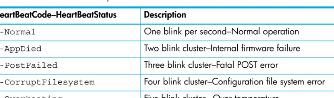
3 Heartbeat LED activity . . . 49
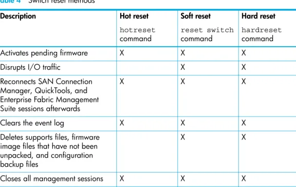
4 Switch reset methods . . . 57
5 Event log message format . . . 109
6 Call Home queue statistics parameters . . . . 138
7 Data capture configuration parameters. . . 140
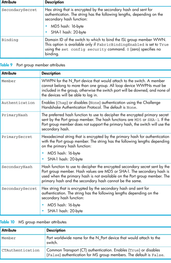
8 ISL group member attributes . . . 159
9 Port group member attributes. . . 160
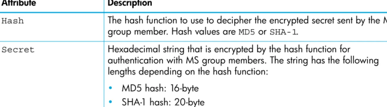
10 MS group member attributes . . . 160
11 Group type parameters . . . 161
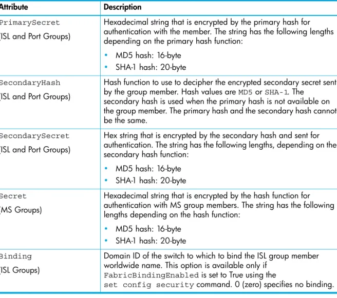
12 Group member attributes . . . 161
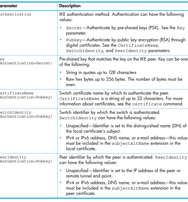
13 IKE peer configuration parameters . . . 171
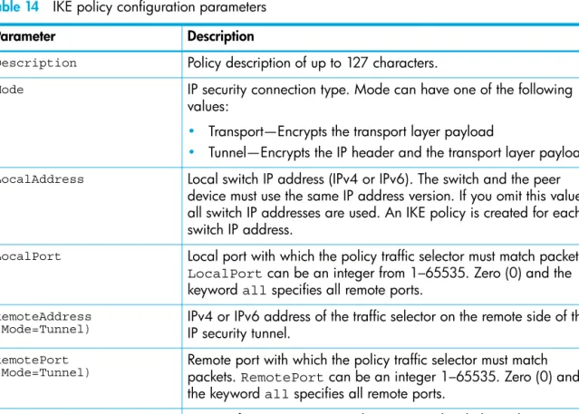
14 IKE policy configuration parameters . . . 176
15 Association configuration parameters. . . 186
16 Policy configuration parameters. . . 192
17 Profile configuration parameters . . . 201
18 Call Home service configuration defaults . . . . 208
19 Switch configuration defaults. . . 209
20 Port configuration defaults. . . 209
21 Port threshold alarm configuration defaults . . . 210
22 Zoning configuration defaults . . . 210
28 IPv6 Ethernet configuration defaults . . . 213
29 Event logging configuration defaults. . . 213
30 NTP server configuration defaults. . . 213
31 Timer configuration defaults . . . 213
32 Security configuration defaults. . . 213
33 Output stream alarm parameters . . . 219
34 Beacon state parameters . . . 220
35 Port configuration parameters . . . 221
36 Security configuration parameters . . . 225
37 Port binding configuration parameters . . . 226
38 Switch configuration parameters . . . 227
39 Port alarm threshold parameters . . . 229
40 Zoning configuration parameters. . . 231
41 Component event monitoring filter parameters. . . 232
42 Event display filter parameters. . . 233
43 Severity level monitoring parameters . . . 233
44 Port monitoring parameters . . . 233
45 Pagebreak state parameters . . . 235
46 Transmission speed parameters . . . 236
47 Port administrative state parameters . . . 236
48 Call Home service configuration attributes . . . . 237
49 Common RADIUS server configuration attributes . . . 239
50 Server-specific RADIUS server configuration attributes . . . 239
51 Switch services settings. . . 242
52 Common SNMP configuration parameters . . . 245
53 SNMP trap configuration parameters . . . 246
54 DNS host name configuration parameters. . . 248
55 IPv4 Ethernet configuration parameters. . . 249
56 IPv6 Ethernet configuration parameters. . . 249
57 Event logging configuration parameters . . . . 250
58 NTP server configuration parameters . . . 250
59 Timer configuration parameters . . . 251
60 Switch administrative state parameters . . . 255
61 Show about display entries . . . 257
62 Log monitoring components . . . 275
63 Event log display filter parameters . . . 276
64 Transceiver information . . . 280
65 Name server display parameters . . . 283
66 Show port display entries . . . 287
67 Switch operational parameters . . . 300
68 Show version display entries . . . 308
69 SNMP version 3 user account parameters. . . 312
70 Offline port loopback types. . . 316
71 Port test parameters . . . 316
72 Connectivity loopback types . . . 320
73 Offline loopback types . . . 320
74 Switch test parameters . . . 320
75 Zoning database parameters . . . 336
76 Zoning database limits . . . 339
1
Command Line Interface Usage
This chapter describes how to use the command line interface.
NOTE: Throughout this document, references in the text to commands and keywords use initial capitalization for clarity. Actual command and operand entries are not case-sensitive.
Logging in to the switch through Telnet
To log in to a switch through Telnet:1. Open a command line window on the workstation and enter the telnet command followed by the
switch Internet Protocol (IP) address: # telnet ip_address
The IP address can be one of the following: • 4-byte IP version 4 (IPv4) address • 16-byte IP version 6 (IPv6) address
• Domain Name System (DNS) host name (requires a DNS server) The Telnet window opens prompting you for a login.
2. Enter an account name and password. The default account name is admin, and its password is password.
switch login:admin password: xxxxxxxx
The following warning appears each time you log in until you change the default password. Warning: Your user account password has not been changed. It is strongly recommended that you do so before proceeding.
To log off, enter the exit command:
SN6000 FC Switch #> exit
To log in to a switch through the serial port:
1. Configure the workstation port with the following settings: • 9,600 baud
• 8-bit character • 1 stop bit • No parity
2. Enter an account name and password when prompted. The default account name is admin, and its
password is password.
NOTE: A switch supports a combined maximum of 19 logins or sessions, which are reserved as follows:
• 4 logins or sessions for internal applications, such as management server and Simple Network Management Protocol (SNMP)
• 9 high priority Telnet sessions
• 6 logins or sessions for SAN Connection Manager (SCM) inband and out-of-band logins, QuickTools logins, Enterprise Fabric Management Suite logins, and Telnet logins.
Additional logins will be refused.
Opening and closing an admin session
The command line interface (CLI) performs monitoring and configuration tasks. Commands that perform monitoring tasks are available to all user accounts. Commands that perform configuration tasks are available only after entering the admin start command to open an Admin session. A user account must
have Admin authority to enter the admin start command.
The following is an example of how to open and close an Admin session: SN6000 FC Switch #> admin start
SN6000 FC Switch (admin) #> .
. .
SN6000 FC Switch (admin) #> admin end
Entering commands
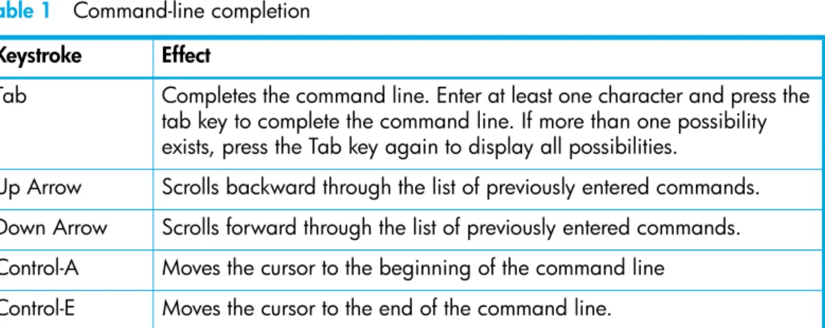
The command-line completion feature makes entering and repeating commands easier. Table 1 describes the command-line completion keystrokes.
Table 1 Command-line completion Keystroke Effect
Tab Completes the command line. Enter at least one character and press the tab key to complete the command line. If more than one possibility exists, press the Tab key again to display all possibilities.
Up Arrow Scrolls backward through the list of previously entered commands. Down Arrow Scrolls forward through the list of previously entered commands. Control-A Moves the cursor to the beginning of the command line
Control-E Moves the cursor to the end of the command line. Control-U Clears the command line.
Getting help
To display help for a command, enter the help command followed by the command you are inquiring
about. The following is an example of the help that is available for the config edit command.
SN6000 FC Switch #> help config edit config edit [CONFIG_NAME]
This command initiates a configuration session and places the current session into config edit mode.
If CONFIG_NAME is given and it exists, it gets edited; otherwise, it gets created. If it is not given, the currently active configuration is edited. Admin mode is required for this command.
Usage: config edit [CONFIG_NAME]
Setting page breaks
Some display commands deliver so much information to the screen that it scrolls by too quickly to read it. You can limit the display to 20 lines at a time by turning on page breaks. By default, page breaks are turned off.The following is an example of how to turn page breaks on and how it affects the display.
SN6000 FC Switch #> set pagebreak on SN6000 FC Switch #> zone list
Zone ZoneSet ---- Zone1 alpha beta Zone2 delta echo Zone3 sierra tango Zone4 gamma delta
Press any key to continue, 'q' to quit ...
Creating a support file
If you contact technical support about a problem with your switch, they may request that you create and send a support file. This support file contains all of the switch configuration information, which can be helpful in diagnosing the problem. The create support command creates the support file
(dump_support.tgz) on the switch. If your workstation has an File Transfer Protocol (FTP) server, you can
proceed with the command prompts to send the file from the switch to a remote host. Otherwise, you can use FTP to download the support file from the switch to your workstation.
The following example creates a support file and sends it to a remote host using a workstation with an FTP server.
SN6000 FC Switch #> create support
Log Msg:[Creating the support file - this will take several seconds] FTP the dump support file to another machine? (y/n): y
Enter address of ftp server (hostname, IPv4, or IPv6): 10.20.33.130 Login name: johndoe
Enter remote directory name: bin/support
Would you like to continue downloading support file? (y/n) [n]: y Connected to 10.20.33.130 (10.20.33.130).
220 localhost.localdomain FTP server (Version wu-2.6.1-18) ready. 331 Password required for johndoe.
Password: xxxxxxx
230 User johndoe logged in. cd bin/support
250 CWD command successful. lcd /itasca/conf/images
Local directory now /itasca/conf/images bin
200 Type set to I. put dump_support.tgz
local: dump_support.tgz remote: dump_support.tgz 227 Entering Passive Mode (10,20,33,130,232,133)
150 Opening BINARY mode data connection for dump_support.tgz. 226 Transfer complete.
43430 bytes sent in 0.292 secs (1.5e+02 Kbytes/sec) Remote system type is UNIX.
Using binary mode to transfer files.
221-You have transferred 43430 bytes in 1 files.
221-Total traffic for this session was 43888 bytes in 1 transfers. 221 Thank you for using the FTP service on localhost.localdomain.
If your workstation does not have an FTP server, enter the create support command to create the
support file, and then use FTP to download the support file from the switch to your workstation, as shown in the following example:
SN6000 FC Switch #> create support
Log Msg:[Creating the support file - this will take several seconds] FTP the dump support file to another machine? (y/n): n
To download the support file from the switch to the workstation:
1. Open a terminal window and move to the directory where you want to download the support file.
2. Enter the ftp command and the switch IP address or symbolic name.
>ftp 10.0.0.1
3. When prompted for a user and password, enter the FTP account name and password (images, images).
user: images password: images
4. Set binary mode and use the get command to download the file (dump_support.tgz).
ftp>bin
ftp>get dump_support.tgz
xxxxx bytes sent in xx secs. ftp>quit
Downloading and uploading files
Several files that reside on the switch can be downloaded to the workstation for examination or for safekeeping. These files include the following:
• Backup configuration file (configdata)
• Log files (logfile)
• Support files (dump_support.tgz)
You can upload firmware image files or backup configuration files to the switch to reinstall firmware or restore a corrupted configuration. The switch uses FTP to exchange files between the switch and the workstation.
To download a file from the switch to the workstation:
1. Enter the ftp command and the switch IP address or symbolic name.
>ftp 10.0.0.1
2. When prompted for a user and password, enter the FTP account name and password (images, images).
user: images password: images
3. Set binary mode and use the get command to download the file (configdata).
ftp>bin
ftp>get configdata
xxxxx bytes sent in xx secs. ftp>quit
To upload a file from the workstation to the switch:
1. Enter the ftp command and the switch IP address or symbolic name.
>ftp 10.0.0.1
2. When prompted for a user and password, enter the FTP account name and password (images, images).
user:images password: images
3. Set binary mode and use the put command to upload the file (config_switch_169).
ftp>put config_switch_169 configdata xxxxx bytes sent in xx secs. ftp>quit
For more information about reinstallation, backup and restore, and creating support and log files:
• See ”Installing firmware” (page 58).
• See ”Backing up and restoring a switch configuration” (page 54).
• See ”Creating and downloading a log file” (page 112).
2
User Account Configuration
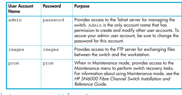
User accounts and their respective passwords are the first line of switch security. A user account consists of an account name, an authority level, and an expiration date. Switches come from the factory with certain user accounts defined for special purposes. Table 2 describes these accounts, their passwords, and their purpose. These accounts cannot be deleted from the switch.
Displaying user account information
You can display all user accounts defined on the switch (useraccounts command) or just those user
accounts that are logged on (user list or show users commands).
The following example displays all user accounts defined on the switch. Account information includes account name, authority, and expiration date.
SN6000 FC Switch (admin) #> user accounts Current list of user accounts
images (admin authority = False, never expires) admin (admin authority = True , never expires)
chuckca (admin authority = False, expires in < 50 days) gregj (admin authority = True , expires in < 100 days) fred (admin authority = True , never expires)
The following example displays user accounts that are logged on to the switch: SN6000 FC Switch (admin) #> user list
User Ethernet Addr-Port Logged in Since ---- ---
admin@OB-session1 10.20.68.108-1031 day month date time year admin@OB-session2 10.20.68.108-1034 day month date time year snmp@OB-session3 Unknown day month date time year snmp@IB-session4 Unknown day month date time year admin@OB-session5 Unknown day month date time year
Table 2 Factory user accounts User Account
Name Password Purpose
admin password Provides access to the Telnet server for managing the
switch. Admin is the only account name that has
permission to create and modify other user accounts. To secure your admin user account, be sure to change the password for this account.
images images Provides access to the FTP server for exchanging files
between the switch and the workstation.
prom prom When in Maintenance mode, provides access to the
Maintenance menu to perform switch recovery tasks. For information about using Maintenance mode, see the
HP SN6000 Fibre Channel Switch Installation and Reference Guide.
Creating user accounts
A user account consists of an account name, an authority level, and an expiration date, which have the following requirements:
• The account name can be up to 15 characters: the first character must be alphanumeric; the remaining characters must be American Standard Code for Information Interchange (ASCII) characters except semicolon (;), comma (,), #, and period (.).
• The authority level grants admin authority (true) or denies it (false).
• The expiration date sets the date when the user account expires.
Only the Admin user account can create user accounts. Add user accounts with the user add command.
The following example creates a new user account named user1 with admin authority that expires in 100 days.
SN6000 FC Switch (admin) #> user add
Press 'q' and the ENTER key to abort this command. account name (1-15 chars) : user1
account password (8-20 chars) : ******* please confirm account password: *******
set account expiration in days (0-2000, 0=never): [0] 100 should this account have admin authority? (y/n): [n] y OK to add user account 'user1' with admin authority and to expire in 100 days?
Please confirm (y/n): [n] y
Modifying user accounts and passwords
Only the admin user account can modify a user account, delete a user account, or change the password
of another user account. However, all user accounts can change their own passwords.
• The user command edits and deletes user accounts.
• The passwd command changes passwords.
The following example removes the expiration date and admin authority for the user account named
user1.
SN6000 FC Switch (admin) #> user edit
Press 'q' and the ENTER key to abort this command. account name (1-15 chars) : user1
set account expiration in days (0-2000, 0=never): [0] should this account have admin authority? (y/n): [n] OK to modify user account 'user1' with no admin authority and to expire in 0 days?
Please confirm (y/n): [n]
The following example deletes the user account named user3.
SN6000 FC Switch (admin) #> user delete user3
In the following example, the admin user account changes the password for the user account named user2.
SN6000 FC Switch #> admin start
SN6000 FC Switch (admin) #> passwd user2
Press 'q' and the ENTER key to abort this command. account OLD password : ********
account NEW password (8-20 chars) : ******** please confirm account NEW password: ******** password has been changed.
3
Network Configuration
Network configuration consists of the IP parameters that identify the switch in the network and provide for IP security. This chapter describes the network configuration tasks.
Displaying the network configuration
The show fabric command displays IP addresses (Enet IP Addr) for all switches in the fabric, as
shown in the following example.
SN6000 FC Switch #> show fabric Domain *133(0x85) WWN 10:00:00:c0:dd:0d:53:91 SymbolicName SN6000 FC Switch HostName <undefined> EthIPv4Address 10.20.116.133 EthIPv6Address <undefined> * indicates principal switch
The show setup system command displays the entire switch network configuration, which includes the
following:
• IP configurations (versions 4 and 6)
• DNS server configuration
To display specific information, add the corresponding keyword. For example, to display IPv6 configuration information, enter the show setup system ipv6 command:
SN6000 FC Switch #> show setup system ipv6 System Information EthIPv6NetworkEnable False EthIPv6NetworkDiscovery Static EthIPv6NetworkAddress 2001::1/64 EthIPv6GatewayAddress fe80::1
Configuring the Ethernet port
Use the set setup system command in an Admin session to configure the Ethernet port and other
network parameters. You can configure all of the following parameters in one session, or you can configure specific parameters by adding the corresponding keyword:
• IPv4 configuration, page 22
• IPv6 configuration, page 23
• DNS server configuration, page 24
IPv4 configuration
The switch supports IPv4, which includes the following:
• Network discovery method
• IP address
• Subnet mask
• IP gateway address
The network discovery method determines how the switch acquires its IP address. The IP address can come from the IP address that resides on the switch or from a server. The switch supports network discovery from the following server types:
• Bootstrap Protocol (BootP)
• Reverse Address Resolution Protocol (RARP)
• Dynamic Host Configuration Protocol (DHCP)
To configure the IPv4 parameters, enter the set setup system ipv4 command:
SN6000 FC Switch (admin) #> set setup system ipv4
A list of attributes with formatting and current values will follow.
Enter a new value or simply press the ENTER key to accept the current value. If you wish to terminate this process before reaching the end of the list press 'q' or 'Q' and the ENTER key to do so.
Current Values: EthIPv4NetworkEnable True EthIPv4NetworkDiscovery Static EthIPv4NetworkAddress 10.20.116.133 EthIPv4NetworkMask 255.255.255.0 EthIPv4GatewayAddress 10.20.116.1
New Value (press ENTER to accept current value, 'q' to quit, 'n' for none): EthIPv4NetworkEnable (True / False) :
EthIPv4NetworkDiscovery (1=Static, 2=Bootp, 3=Dhcp, 4=Rarp) :
EthIPv4NetworkAddress (dot-notated IP Address) : 10:20:30:40 EthIPv4NetworkMask (dot-notated IP Address) : 255.0.0.0 EthIPv4GatewayAddress (dot-notated IPv4 Address) : 10.20.30.254 Do you want to save and activate this system setup? (y/n): [n] y
IPv6 configuration
The switch supports IPv6, which includes the following:
• Network discovery method
• IP address
• IP gateway address
The network discovery method determines how the switch acquires its IP address. The IP address can come from the IP address (static) that resides on the switch or from a DHCP server; or it can be learned from
a router through the Neighbor Discovery Protocol (NDP). To configure the IPv6 parameters, enter the
set setup system ipv6 command:
SN6000 FC Switch (admin) #> set setup system ipv6
A list of attributes with formatting and current values will follow.
Enter a new value or simply press the ENTER key to accept the current value. If you wish to terminate this process before reaching the end of the list press 'q' or 'Q' and the ENTER key to do so.
Current Values:
EthIPv6NetworkEnable False EthIPv6Discovery Static EthIPv6NetworkAddress <undefined> EthIPv6GatewayAddress <undefined>
New Value (press ENTER to accept current value, 'q' to quit, 'n' for none): EthIPv6NetworkEnable (True / False) :
EthIPv6Discovery (1=Static, 2=Dhcpv6, 3=Ndp) : EthIPv6NetworkAddress (IPv6 Address/Mask Length format) : EthIPv6GatewayAddress (IPv6 Address) : Do you want to save and activate this system setup? (y/n): [n]
DNS server configuration
A DNS server manages the host names for a fabric. This enables you to specify servers and switches by a meaningful name rather than IP address. To configure a DNS server, enter the set setup system dns
command in an Admin session, as shown in the following example: SN6000 FC Switch (admin) #> set setup system dns
A list of attributes with formatting and current values will follow.
Enter a new value or simply press the ENTER key to accept the current value. If you wish to terminate this process before reaching the end of the list press 'q' or 'Q' and the ENTER key to do so.
Current Values: DNSClientEnabled False DNSLocalHostname <undefined> DNSServerDiscovery Static DNSServer1Address <undefined> DNSServer2Address <undefined> DNSServer3Address <undefined> DNSSearchListDiscovery Static DNSSearchList1 <undefined> DNSSearchList2 <undefined> DNSSearchList3 <undefined> DNSSearchList4 <undefined> DNSSearchList5 <undefined>
New Value (press ENTER to accept current value, 'q' to quit, 'n' for none): DNSClientEnabled (True / False) :
DNSLocalHostname (hostname) : DNSServerDiscovery (1=Static, 2=Dhcp, 3=Dhcpv6) : DNSServer1Address (IPv4, or IPv6 Address) : DNSServer2Address (IPv4, or IPv6 Address) : DNSServer3Address (IPv4, or IPv6 Address) : DNSSearchListDiscovery (1=Static, 2=Dhcp, 3=Dhcpv6) : DNSSearchList1 (domain name) : DNSSearchList2 (domain name) : DNSSearchList3 (domain name) : DNSSearchList4 (domain name) : DNSSearchList5 (domain name) : Do you want to save and activate this system setup? (y/n): [n]
Verifying a switch in the network
You can use the ping command to verify that a switch is communicating in the network. The following
example successfully tests the network for a switch with IP address 10.20.11.57. SN6000 FC Switch #> ping 10.20.11.57
Ping command issued. Waiting for response... SN6000 FC Switch #>
Response successfully received from 10.20.11.57. If the switch was unreachable, you would see the following display:
SN6000 FC Switch #> ping 10.20.11.57
Ping command issued. Waiting for response... No response from 10.20.11.57. Unreachable.
Managing IP security
To modify IP security, you must open an Admin session with the admin start command, then open an
Ipsec Edit session with the ipsec edit command. The Admin session prevents other accounts from
making changes at the same time through Telnet, SAN Connection Manager, or any other management application. The Ipsec Edit session provides access to the ipsec, ipsec association
ipsec policy, ike peer, and ike policy commands with which you make modifications to the IP
security configuration, as shown in the following example: SN6000 FC Switch #> admin start
SN6000 FC Switch (admin) #> ipsec edit SN6000 FC Switch (admin-ipsec)#> ipsec . . .
SN6000 FC Switch (admin-ipsec)#> ipsec policy . . . SN6000 FC Switch (admin-ipsec)#> ipsec association. . . SN6000 FC Switch (admin-ipsec)#> ike peer . . .
SN6000 FC Switch (admin-ipsec)#> ike policy . . .
The ipsec save command saves the changes you made during the Ipsec Edit session. Changes take
effect immediately.
SN6000 FC Switch (admin-ipsec)#> ipsec save
To close the Ipsec Edit session without saving changes, enter the ipsec cancel command.
SN6000 FC Switch (admin-ipsec)#> ipsec cancel
The admin end command releases the Admin session for other administrators when you are finished
making changes to the switch.
To remove all IP security policies, security associations, IKE peers, and IKE polices, enter the reset ipsec command.
SN6000 FC Switch (admin) #> reset ipsec
The following subsections describe IP security concepts and IP security management tasks.
IP security concepts
IP security provides encryption-based security for IPv4 and IPv6 communications between devices through the use of security policies and associations. The Internet key exchange (IKE) protocol automates the creation of IP security associations on the switch and connected devices, and the sharing of encryption keys through the configuration of IKE peers and policies. The security association database comprises all IP security associations. The security policy database comprises all IP security policies. The IKE database comprises all IKE policies and peers.
IMPORTANT: IP security configurations can be complex: it is possible to unintentionally configure policies and associations that isolate a switch from all communication. If this happens, you can disable IP security by placing the switch in maintenance mode, and correct the problem through the serial port interface. For information about using maintenance mode and connecting through the serial port, see the HP SN6000 Fibre Channel Switch Installation and Reference Guide.
Security policies and associations
Security policies are located in the security policy database and define the following parameters:
• Connection source and destination
• Data traffic direction: inbound or outbound
• Protocols for which to protect data traffic
from the source to the destination, and another for inbound traffic to the source from the destination. You can specify sources and destinations by IP addresses (version 4 or 6) or DNS host names. If a host name resolves to more than one IP address, the switch creates the necessary policies and associations. You can recognize these dynamic policies and associations because their names begin with DynamicSP_ and
DynamicSA_ respectively.
A security association defines the encryption algorithm and encryption key (public key or secret) to apply when called by a security policy. A security policy may call several associations at different times, but each association is related to only one policy. The security association database is the set of all security associations.
You can apply IP security to all communication between two systems, or to selected protocols, such as the Internet Control Message Protocol (ICMP), Transmission Control Protocol (TCP), or the User Datagram Protocol (UDP). Furthermore, instead of applying IP security, you can choose to discard all inbound or outbound traffic, or to allow all traffic without encryption. Both the AH and ESP security protocols provide source authentication, ensure data integrity, and protect against replay.
IKE peers and policies
IKE is a protocol that automates the configuration of matching IP security associations on the switch and on the connected device (or peer). The IKE peer defines the IKE security association connection through which the IKE policy configures the IP security associations.The IKE policy defines the type of data traffic to secure between the switch and the peer, and how to encrypt that data. You must create the same IKE peer and IKE policy configurations on the switch and the peer device.
Public key infrastructure
Public key encryption requires a public key, a corresponding private key, and the necessary certificates to authenticate them. Public key infrastructure (PKI) provides support for the creation and management of public/private key pairs, signed certificates, and certificate authority (CA) certificates when using IKE. You can create a public/private key and combine it with one or more device identities to generate a certificate request. Submit the certificate request to a CA to obtain a signed certificate, which contains the
authenticated public/private key pair. In addition to the signed certificate, you must also obtain a CA certificate to authenticate the CA. After downloading the signed certificate and a CA certificate to the switch and importing them into the PKI database, the signed certificate (which contains the authenticated public key) can then be used to complete the IKE peer configuration.
Displaying IP security information
You can display the following types of IP security configuration information:
• IP security policy and association information, page 26
• IKE peer and policy information, page 27
• Public key infrastructure information, page 27
• IP security configuration history, page 28
• IP security configuration limits, page 28
IP security policy and association information
To display general or specific policy and association information, enter the ipsec list command. The ipsec list command does not require an Admin session nor an Ipsec Edit session. Within an Ipsec Edit
session, the ipsec associationlist and ipsec policylist commands display the same
information. You can display active, configured, and edited polices and associations:
• Active—policies and associations currently in use
• Configured—policies and associations that have been saved in the IP security database
The following example displays all active policies and associations: SN6000 FC Switch #> ipsec list
Active IPsec Information Security Association Database h2h-sh-sa
h2h-hs-sa
Security Policy Database h2h-hs-sp
h2h-sh-sp Summary
Security Association Count: 2 Security Policy Count: 2
IKE peer and policy information
To display general or specific peer and policy information, enter the ike list command. The ike list
command does not require an Admin session nor an Ipsec Edit session. Within an Ipsec Edit session, the
ike peerlist and ike policylist commands display the same information. You can display
active, configured, and edited peers and polices:
• Active—peers and policies currently in use
• Configured—peers and policies that have been saved in the IKE database
• Edited—peers and policies that are being edited, but have not yet been saved The following example displays all configured IKE peers and policies:
SN6000 FC Switch #> ike list configured Configured (saved) IKE Information Peer Policy -- peer_1 policy_1 policy_2 peer_2 policy_3 peer_3 (no policies) (No peer) policy_4 Summary: Peer Count 3 Policy Count 4
Public key infrastructure information
To display information in the PKI database about public/private key pairs, signed certificates, and certificate authorities, enter the following commands:
• keylist
• certificatelist local
The following is an example of the Key List command for key512: SN6000 FC Switch #> key list key512
Key key512:
private key with: pubkey: RSA 512 bits
keyid: 49:80:4c:aa:d3:c3:bc:c7:f5:b1:41:34:ce:71:48:1d:b9:b3:d9:f9 subjkey: f4:b6:b9:27:25:7a:5a:69:a0:9e:cf:14:cd:3c:88:e9:d5:b1:aa:4a The following is an example of the Key List command:
SN6000 FC Switch #> key list Installed Keys:
key512 key2048 key1024
* indicates key has a matching local certificate
IP security configuration history
To display the IP security configuration history, enter the ipsec history command to display a record
of policy and association modifications, as shown in the following example: SN6000 FC Switch #> ipsec history
IPsec Database History
ConfigurationLastEditedBy johndoe@OB-session5 ConfigurationLastEditedOn Sat Mar 8 07:14:36 2008 Active Database Checksum 00000144
Inactive Database Checksum 00000385 IKE Database Checksum 00000023 History includes the following information:
• Time of the most recent activation and the user account that performed it
• Time of the most recent modification to the IP security configuration and the user account that made it
• Checksum for the active and inactive databases
• Checksum for the IKE database
IP security configuration limits
To display a summary of the objects in the IP security configuration and their maximum limits, enter the
ipsec limits command, as shown in the following example:
SN6000 FC Switch #> ipsec limits Configured (saved) IPsec Information
IPsec Attribute Maximum Current - MaxConfiguredSAs 512 0 MaxConfiguredSPs 128 0 MaxConfiguredIKEPeers 16 0 MaxConfiguredIKEPolicies 256 0
In an Ipsec Edit session, the ipsec limits command displays the number of both configured
associations and policies, plus those created in the edit session but not yet saved.
Managing the security policy database
The security policy database is made up of user-defined policies and dynamic policies (policies created by the switch). In addition to creating a policy, you can delete, modify, rename, and copy user-defined policies. Dynamic policies can only be copied.
Creating a policy
To create a policy, enter the ipsec policy create command as shown in the following example:
SN6000 FC Switch #> admin start
SN6000 FC Switch (admin) #> ipsec edit
SN6000 FC Switch (admin-ipsec) #> ipsec policy create h2h-sh-sp A list of attributes with formatting will follow.
Enter a value or simply press the ENTER key to skip specifying a value. If you wish to terminate this process before reaching the end of the list press 'q' or 'Q' and the ENTER key to do so.
Required attributes are preceded by an asterisk. Value (press ENTER to not specify value, 'q' to quit):
Description (string value, 0-127 bytes) :
Host-to-host:switch->host *SourceAddress (IPv4, IPv6 or hostname/[PrefixLength]) :
fe80::2c0:ddff:fe03:d4c1 SourcePort (decimal value, 1-65535) :
*DestinationAddress (IPv4, IPv6 or hostname/[PrefixLength]) :
fe80::250:daff:feb7:9d02 DestinationPort (decimal value, 1-65535) :
*Protocol (decimal value, or keyword) Allowed keywords
icmp, icmp6, ip4, tcp, udp or any : any *Direction (1=in, 2=out) : 2 Priority (value, -2147483647 to +214783647) : *Action (1=discard, 2=none, 3=ipsec) : 3 Mode (1=transport, 2=tunnel) : 2
*TunnelSource (IPv4, or IPv6 Address) : fe91::3d1:eecc:bf14:e5d2 *TunnelDestination (IPv4, or IPv6 Address) : fe91::361:ebcc:bfc8:0e13 *ProtectionDesired (select one, transport-mode only)
1=ah Authentication Header
2=esp Encapsulating Security Payload 3=both : 2 *espRuleLevel (1=default, 2=use, 3=require) : 3 The security policy has been created.
This configuration must be saved with the 'ipsec save' command before it can take effect, or to discard this configuration use the 'ipsec cancel' command.
Deleting a policy
To delete a user-defined policy, enter the ipsec policy delete command, as shown in the following
example:
SN6000 FC Switch #> admin start
SN6000 FC Switch (admin) #> ipsec edit
SN6000 FC Switch (admin-ipsec) #> ipsec policy delete policy_1 The security policy will be deleted. Please confirm (y/n): [n] y SN6000 FC Switch (admin-ipsec) #> ipsec save
The IPsec configuration will be saved and activated. Please confirm (y/n): [n] y
Modifying a user-defined policy
To modify an existing user-defined policy, enter the ipsec policy edit command in an Admin session
and an Ipsec Edit session, as shown in the following example. An asterisk (*) indicates a required entry. SN6000 FC Switch #> admin start
SN6000 FC Switch (admin) #> ipsec edit
SN6000 FC Switch (admin-ipsec) #> ipsec policy edit h2h-sh-sp
A list of attributes with formatting and current values will follow.
Enter a new value or simply press the ENTER key to accept the current value. To remove a value for an optional attribute, use ’n’.
If you wish to terminate this process before reaching the end of the list press 'q' or 'Q' and the ENTER key to do so.
Current Values:
Description Host-to-host: switch->host .
. .
espRuleLevel require
New Value (press ENTER to not specify value, 'q' to quit, 'n' for none): Description (string value, 0-127 bytes) :
*SourceAddress (IPv4, IPv6 or hostname/[PrefixLength]) : SourcePort (decimal value, 1-65535) : *DestinationAddress (IPv4, IPv6 or hostname/[PrefixLength]) : DestinationPort (decimal value, 1-65535) : *Protocol (decimal value, or keyword)
Allowed keywords
icmp, icmp6, ip4, tcp, udp or any : tcp *Direction (1=in, 2=out) : Priority (value, -2147483647 to +2147483647) : *Action (1=discard, 2=none, 3=ipsec) : Mode (1=transport, 2=tunnel) : *TunnelSource (IPv4, or IPv6 Address) : *TunnelDestination (IPv4, or IPv6 Address) : *ProtectionDesired (select one, transport-mode only)
1=ah Authentication Header
2=esp Encapsulating Security Payload
3=both : *ahRuleLevel (1=default, 2=use, 3=require) : *espRuleLevel (1=default, 2=use, 3=require) : The security policy has been edited.
This configuration must be saved with the 'ipsec save' command before it can take effect, or to discard this configuration use the 'ipsec cancel' command.
SN6000 FC Switch (admin-ipsec) #> ipsec save
The IPsec configuration will be saved and activated. Please confirm (y/n): [n] y
Renaming a user-defined policy
To rename a policy (policy_1), enter the ipsec policy rename command, as shown in the following
example:
SN6000 FC Switch #> admin start
SN6000 FC Switch (admin) #> ipsec edit
SN6000 FC Switch (admin-ipsec) #> ipsec policy rename policy_1 policy_4 The security policy will be renamed. Please confirm (y/n): [n] y SN6000 FC Switch (admin-ipsec) #> ipsec save
The IPsec configuration will be saved and activated. Please confirm (y/n): [n] y
Copying a policy
You can copy both user-defined and dynamic policies. To copy a policy (policy_1), enter the ipsec policy copy command, as shown in the following example:
SN6000 FC Switch #> admin start
SN6000 FC Switch (admin) #> ipsec edit
SN6000 FC Switch (admin-ipsec) #> ipsec policy copy policy_1 policy_a SN6000 FC Switch (admin-ipsec) #> ipsec save
The IPsec configuration will be saved and activated. Please confirm (y/n): [n] y
Managing the security association database
The security association database is made up of user-defined associations and dynamic associations (associations created by the switch). In addition to creating an association, you can delete, modify, rename, and copy user-defined associations. Dynamic associations can only be copied.
Creating an association
To create an association, enter the ipsec association create command as shown in the following
example:
SN6000 FC Switch #> admin start
SN6000 FC Switch (admin) #> ipsec edit
SN6000 FC Switch (admin-ipsec) #> ipsec association create h2h-sh-sa A list of attributes with formatting will follow.
Enter a value or simply press the ENTER key to skip specifying a value. If you wish to terminate this process before reaching the end of the list press 'q' or 'Q' and the ENTER key to do so.
Required attributes are preceded by an asterisk. Value (press ENTER to not specify value, 'q' to quit): Description (string value, 0-127 bytes) :
Host-to-host:switch->host *SourceAddress (hostname, IPv4, or IPv6 Address) :
fe80::2c0:ddff:fe03:d4c1 *DestinationAddress (hostname, IPv4, or IPv6 Address) :
fe80::250:daff:feb7:9d02 *Protocol (1=esp, 2=esp-old, 3=ah, 4=ah-old) : 1
*SPI (decimal value, 256-4294967295) : 333 Authentication (select an authentication algorithm) 1=hmac-md5 (16 byte key) 2=hmac-sha1 (20 byte key) 3=hmac-sha256 (32 byte key) 4=aes-xcbc-mac (16 byte key)
authentication algorithm choice : 2 *AuthenticationKey (quoted string or raw hex bytes) :
"12345678901234567890" *Encryption (select an encryption algorithm)
1=des-cbc (8 byte key) 2=3des-cbc (24 byte key) 3=null (0 byte key) 4=blowfish-cbc (5-56 byte key) 5=aes-cbc (16/24/32 byte key) 6=twofish-cbc (16-32 byte key) encryption algorithm choice : 2 *EncryptionKey (quoted string or raw hex bytes) :
"123456789012345678901234" Mode (1=transport, 2=tunnel) : 1
The security association has been created.
This configuration must be saved with the 'ipsec save' command before it can take effect, or to discard this configuration use the 'ipsec cancel' command.
Deleting an association
To delete a user-defined association, enter the ipsec association delete command as shown in the
following example:
SN6000 FC Switch #> admin start
SN6000 FC Switch (admin) #> ipsec edit
SN6000 FC Switch (admin-ipsec) #> ipsec association delete association_1 The security association will be deleted. Please confirm (y/n): [n] y SN6000 FC Switch (admin-ipsec) #> ipsec save
The IPsec configuration will be saved and activated. Please confirm (y/n): [n] y
Modifying a user-defined association
To modify an existing user-defined association, enter the ipsec association edit command in an
Admin session and an Ipsec Edit session as shown in the following example. An asterisk (*) indicates a required entry.
SN6000 FC Switch (admin-ipsec) #> ipsec association edit h2h-sh-sa A list of attributes with formatting and current values will follow.
Enter a new value or simply press the ENTER key to accept the current value. To remove a value for an optional attribute, use ’n’.
If you wish to terminate this process before reaching the end of the list press 'q' or 'Q' and the ENTER key to do so.
Current Values:
Description Host-to-host:switch->host .
.
EncryptionKey 123456789012345678901234
New Value (press ENTER to not specify value, 'q' to quit, 'n' for none): Description (string value, 0-127 bytes) :
*SourceAddress (hostname, IPv4, or IPv6 Address) : *DestinationAddress (hostname, IPv4, or IPv6 Address) : *Protocol (1=esp, 2=esp-old, 3=ah, 4=ah-old) : ah *SPI (decimal value, 256-4294967295) : Authentication (select an authentication algorithm) 1=hmac-md5 (16 byte key) 2=hmac-sha1 (20 byte key) 3=hmac-sha256 (32 byte key) 4=aes-xcbc-mac (16 byte key) authentication algorithm choice : *AuthenticationKey (quotes string or raw hex bytes) : *Encryption (select an encryption algorithm) 1=des-cbc (8 byte key)
2=3des-cbc (24 byte key) 3=null (0 byte key)
4=blowfish-cbc (5-56 byte key) 5=aes-cbc (16/24/32 byte key) 6=twofish-cbc (32 byte key)
encryption algorithm choice : *EncryptionKey (quoted string or raw hex bytes) : Mode (1=transport, 2=tunnel) :
The security association has been edited.
This configuration must be saved with the 'ipsec save' command before it can take effect, or to discard this configuration use the 'ipsec cancel' command.
SN6000 FC Switch (admin-ipsec) #> ipsec save
The IPsec configuration will be saved and activated. Please confirm (y/n): [n] y
Renaming a user-defined association
To rename a user-defined association (association_1), enter the ipsec association rename
command as shown in the following example: SN6000 FC Switch #> admin start
SN6000 FC Switch (admin) #> ipsec edit
SN6000 FC Switch (admin-ipsec) #> ipsec association rename association_1 association_4
The security association will be renamed. Please confirm (y/n): [n] y SN6000 FC Switch (admin-ipsec) #> ipsec save
The IPsec configuration will be saved and activated. Please confirm (y/n): [n] y
Copying an association
You can copy both user-defined and dynamic associations. To copy an association (association_1),
enter the ipsec association copy command as shown in the following example:
SN6000 FC Switch #> admin start
SN6000 FC Switch (admin) #> ipsec edit
SN6000 FC Switch (admin-ipsec) #> ipsec association copy association_1 association_a SN6000 FC Switch (admin-ipsec) #> ipsec save
The IPsec configuration will be saved and activated. Please confirm (y/n): [n] y
Managing IKE peers
An IKE peer defines a peer device and configures the IKE security association through which the switch and peer device establish the IP security associations defined by an IKE policy. The IKE database is made up of IKE peers and policies. In addition to creating an IKE peer, you can delete, modify, rename, and copy user-defined peers.
Creating an IKE peer
To create an IKE peer, enter the ike peer create command as shown in the following example:
SN6000 FC Switch ># admin start
SN6000 FC Switch (admin) #> ipsec edit
SN6000 FC Switch (admin-ipsec) #> ike peer create peer_1 A list of attributes with formatting will follow.
Enter a value or simply press the ENTER key to skip specifying a value. If you wish to terminate this process before reaching the end of the list press 'q' or 'Q' and the ENTER key to do so.
Required attributes are preceded by an asterisk. Value (press ENTER to not specify value, 'q' to quit):
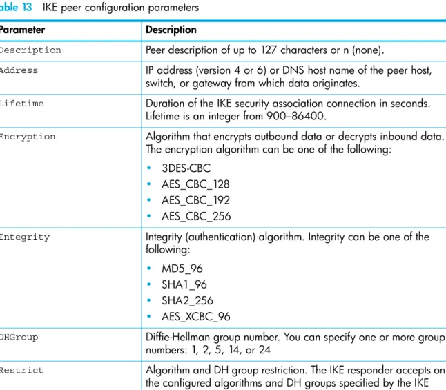
Description (string, max=127 chars, N=None) : Peer 1 *Address (hostname, IPv4, or IPv6 Address) : 10.0.0.3 Lifetime (decimal value, 900-86400 seconds) : 3600 *Encryption (select one or more encryption algorithms)
1=3des_cbc 2=aes_cbc_128 3=aes_cbc_192
4=aes_cbc_256 : 1 4 *Integrity (select one or more integrity algorithms)
1=md5_96 2=sha1_96 3=sha2_256
4=aes_xcbc_96 : 1 2 3 *DHGroup (select one or more Diffie-Hellman Groups)
1, 2, 5, 14, 24 : 2 14 Restrict (True / False) : True *Authentication (1=secret, 2=public_key) : 1 *Key (quoted string or raw hex bytes)
maximum length for quoted string = 128 maximum length for raw hex bytes = 256
the raw hex length must be even : 0x11223344 The IKE peer has been created.
This configuration must be saved with the 'ipsec save' command before it can take effect, or to discard this configuration use the 'ipsec cancel' command.
SN6000 FC Switch (admin-IPSEC) #> ipsec save
Deleting an IKE peer
To delete an IKE peer, enter the ike peer delete command as shown in the following example:
SN6000 FC Switch #> admin start
SN6000 FC Switch (admin) #> ipsec edit
SN6000 FC Switch (admin-ipsec) #> ike peer delete peer_1 The IKE peer will be deleted. Please confirm (y/n): [n] y SN6000 FC Switch (admin-ipsec) #> ipsec save
The IPsec configuration will be saved and activated. Please confirm (y/n): [n] y
Modifying an IKE peer
To modify an existing IKE peer, enter the ike peer edit command in an Admin session and an Ipsec
Edit session as shown in the following example. An asterisk (*) indicates a required entry. SN6000 FC Switch ># admin start
SN6000 FC Switch (admin) #> ipsec edit
SN6000 FC Switch (admin-ipsec) #> ike peer edit peer_1
A list of attributes with formatting and current values will follow.
Enter a new value or simply press the ENTER key to accept the current value. If you wish to terminate this process before reaching the end of the list press ’q’ or ’Q’ and the ENTER key to do so.
Current Values:
Description Peer 1 Address 10.0.0.3 Lifetime 3600 (seconds) Encryption 3des_cbc aes_cbc_256 Integrity md5_96 sha1_96 sha2_256 DHGroup 2 14
Restrict True Authentication secret Key 0x1122334
New Value (press ENTER to not specify value, 'q' to quit, 'n' for none): Description (string, max=127 chars, N=None) :
*Address (hostname, IPv4, or IPv6 Address) : 10.1.2.3 Lifetime (decimal value, 900-86400 seconds) :
*Encryption (select one or more encryption algorithms) 1=3des_cbc
2=aes_cbc_128 3=aes_cbc_192
4=aes_cbc_192 : *Integrity (select one or more integrity algorithms) 1=md5_96
2=sha1_96 3=sha2_256
4=aes_xcbc_96 : *DHGroup (select one or more Diffie-Hellman Groups)
1 , 2, 5, 14, 24 :
Restrict (True / False) : False Authentication (1=secret) :
*Key (quoted string or raw hex bytes)
maximum length for quoted string = 128 maximum length for raw hex bytes = 256 the raw hex length must be even : The IKE peer has been edited.
This configuration must be saved with the ’ipsec save’ command before it can take effect, or to discard this configuration use the ’ipsec cancel’ command.
Renaming an IKE peer
To rename an IKE peer (peer_1), enter the ike peer rename command as shown in the following
example:
SN6000 FC Switch #> admin start
SN6000 FC Switch (admin) #> ipsec edit
SN6000 FC Switch (admin-ipsec) #> ike peer rename peer_1 peer_4 The IKE peer will be renamed. Please confirm (y/n): [n] y SN6000 FC Switch (admin-ipsec) #> ipsec save
The IPsec configuration will be saved and activated. Please confirm (y/n): [n] y
Copying an IKE peer
To copy an IKE peer (peer_1), enter the ike peer copy command as shown in the following example:
SN6000 FC Switch #> admin start
SN6000 FC Switch (admin) #> ipsec edit
SN6000 FC Switch (admin-ipsec) #> ike peer copy peer_1 peer_a SN6000 FC Switch (admin-ipsec) #> ipsec save
The IPsec configuration will be saved and activated. Please confirm (y/n): [n] y
Managing IKE policies
An IKE policy defines and configures the IP security association on the switch and the peer device by which data traffic is selected and encrypted. The IKE database is made up of the IKE policies and peers. In addition to creating an IKE policy, you can delete, modify, rename, and copy user-defined policies.
Creating an IKE policy
To create an IKE peer, enter the ike policy create command as shown in the following example:
SN6000 FC Switch (admin-ipsec) #> ike policy create policy_2 A list of attributes with formatting will follow.
Enter a value or simply press the ENTER key to skip specifying a value. If you wish to terminate this process before reaching the end of the list press 'q' or 'Q' and the ENTER key to do so.
Required attributes are preceded by an asterisk. Value (press ENTER to not specify value, 'q' to quit):
Description (string, max=127 chars, N=None) : Policy 2 *Mode (1=transport, 2=tunnel) : 1
*LocalAddress (IPv4, IPv6 Address or keyword 'All' : 10.0.0.3 LocalPort (decimal value, 0-65535 or keyword 'All' : 1234 RemotePort (decimal value, 0-65535 or keyword 'All' : 0 *Peer (string, max=32 chars) : peer_1 *Protocol (decimal value, 0-255, or keyword)
0=NotSpecified Allowed keywords
icmp, icmp6, ip4, tcp, udp or any : udp Action (1=ipsec) : 1 ProtectionDesired (select one, transport-mode only)
1=esp Encapsulating Security Payload : 1 LifetimeChild (decimal value, 900-86400 seconds) : 3600 RekeyChild (True / False) : True *Encryption (select one or more encryption algorithms)
1=3des_cbc 2=aes_cbc_128 3=aes_cbc_192 4=aes_cbc_256
5=null : 1 Integrity (select one or more integrity algorithms) 1=md5_96
2=sha1_96 3=sha2_256 4=aes_xcbc_96
or the keyword 'None' : 1 2 3 DHGroup (select one or more Diffie-Hellman Groups)
1, 2, 5, 14, 24 or the keyword 'None' : 1 5 Restrict (True / False) : True The IKE policy has been created.
This configuration must be saved with the 'ipsec save' command before it can take effect, or to discard this configuration use the 'ipsec cancel' command.
Deleting an IKE policy
To delete an IKE policy, enter the ike policy delete command as shown in the following example:
SN6000 FC Switch #> admin start
SN6000 FC Switch (admin) #> ipsec edit
SN6000 FC Switch (admin-ipsec) #> ike policy delete policy_1 The IKE policy will be deleted. Please confirm (y/n): [n] y SN6000 FC Switch (admin-ipsec) #> ipsec save
The IPsec configuration will be saved and activated. Please confirm (y/n): [n] y