Manipulator and Object Tracking for In Hand Model Acquisition
Michael Krainin, Peter Henry, Xiaofeng Ren, and Dieter Fox
Abstract— Recognizing and manipulating objects is anim-portant task for mobile robots performing useful services in everyday environments. While existing techniques for object recognition related to manipulation provide very good results even for noisy and incomplete data, they are typically trained using data generated in an offline process. As a result, they do not enable a robot to acquire new object models as it operates in an environment. In this paper, we develop an approach to building 3D models of unknown objects based on a depth camera observing the robot’s hand while moving an object. The approach integrates both shape and appearance information into an articulated ICP approach to track the robot’s manipulator and the object. Objects are modeled by sets of surfels, which are small patches providing occlusion and appearance information. Experiments show that our approach provides very good 3D models even when the object is highly symmetric and lacking visual features and the manipulator motion is noisy.
I. INTRODUCTION
The ability to recognize and manipulate objects is an important task for mobile robots performing useful services in everyday environments. Over the last years, various research groups have made substantial progress in recognition and manipulation of everyday objects [20, 5, 2, 4, 12, 19, 8]. While the developed techniques are often able to deal with noisy data and incomplete models, they still have limitations with respect to their usability in long term robot deployments in realistic environments. One crucial limitation is due to the fact that the parameters of the object recognition algorithms are either set manually or trained using offline machine learning techniques. As a result, there is no provision for enabling a robot to autonomously acquire new object models as it operates in an environment. This is an important limitation, since no matter how extensive the training data, a robot might always be confronted with a novel object (type) when operating in an unknown environment.
The goal of our work is to develop techniques that enable robots to autonomously acquire models of unknown objects. Ultimately, such a capability will allow robots to actively investigate their environments and learn about objects in an incremental way, adding more and more knowledge over time. In addition to shape and appearance information, object mod-els could contain information such as the weight, type, typical location, or grasp properties of the object. Equipped with these techniques, robots can become experts in their respective environments and share information with other robots, thereby allowing for rapid progress in robotic capabilities.
M. Krainin, P. Henry, and D. Fox are with the Department of Computer Science & Engineering, University of Washington, Seattle, WA 98195, USA
mkrainin,peter,[email protected]
X. Ren is with the Intel Labs Seattle, Seattle, WA 98195, USA
D. Fox is also with the Intel Labs Seattle, Seattle, WA 98195, USA
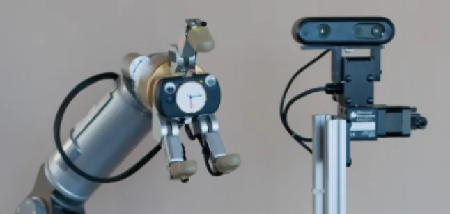
Fig. 1. Experimental setup. We used a WAM arm with BarrettHand on a Segway base. Mounted next to the arm on a pan-tilt unit is a depth camera.
In this paper, we present a first step toward this goal. Specifically, we develop an approach to building a 3D surface model of an unknown object based on data collected by a depth camera observing the robot’s hand moving the object. In contrast to existing work in 3D object modeling [16, 6], our approach does not require a highly accurate depth sensor or a static or unobstructed view of the object. Neither does our approach require an extremely precise manipulator as in existing work on using robots to model objects [11]. This point is essential because our manipulator can experience multiple cm errors caused by cable stretch. It is also an important feature if such techniques are to be used in robots priced for consumer use.
We develop a Kalman filter that uses depth and visual in-formation to track the configuration of the robot’s manipulator along with the object in the robot’s hand. By doing so, our approach can compensate for noise in the manipulator’s joint sensors and provide an accurate estimate for the trajectory of the object. Over time, an increasingly complete 3D model of the object is generated by extracting points from each depth scan and aligning them according to the tracked hand and object position. The approach integrates the scans into a consistent surface model using surfels, small discs which represent local surface patches [9, 25]. Experiments show that our approach can generate good models even for objects that are highly symmetric, such as coffee cups, and objects lacking visual texture.
Our work provides the following contributions. We develop a Kalman filter based framework for tracking a robot ma-nipulator and an unknown object grasped by the hand. We show how a 3D model of the object can be generated as part of the tracking algorithm. We develop a novel version of articulated ICP that incorporates uncertainty estimates from the Kalman filter, correspondences from visual feature match-ing, and occlusion information from the surfel model. Finally, we demonstrate our first results with an end-to-end system, capable of grasping unknown objects, acquiring a model of the object, and placing it back on a table. We also show that
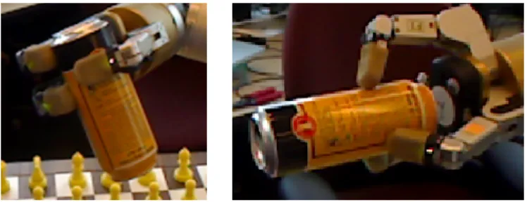
Fig. 2. (left) A Barrett Hand holding a box. (right) Rendering of the depth map provided by our depth camera.
our technique is capable of resuming modeling after the object is placed down and regrasped.
This paper is organized as follows. In the next section, we first describe our Kalman filter approach to tracking a robot’s manipulator and an object grasped by the hand. We then introduce an extension to articulated ICP to smoothly in-corporate it into our tracking approach. We then go into detail on the modeling process in Section III. Then, in Section IV, we discuss related work, followed by experimental results. Finally, we conclude in Section VI.
II. JOINT MANIPULATOR AND OBJECT TRACKING Our goal is to acquire 3D models of objects grasped by a robot’s manipulator. To do so, we assume that the robot is equipped with a 3D depth sensor that observes the robot’s manipulation space, producing 3D, colored point-clouds of the robot’s manipulator and the object grasped by the hand. Fig. 2 shows an example image along with depth information of a BarrettHand holding a box. To use such a point cloud for tracking, we assume that the robot has a 3D model of its manipulator. Such a model can either be generated from design drawings or measured in an off line process. The 3D model allows us to generate an expected point cloud measurement for any configuration of the manipulator. In our current system, we use a one-time ray-casting on an existing model of the WAM Arm and BarrettHand included with OpenRAVE. In the future, we plan to investigate techniques similar to Sturm et al. [21] to instead learn these models.
A. Kalman Filter Tracking and Object Generation
We use a Kalman filter to track three components in the state vectorµ=!θ,ˆTˆcalib,Tˆobj":
• The manipulator joint anglesθ.ˆ
• The transformationTˆcalib, representing an adjustment to
the initial robot to camera calibration, which transforms the base of the manipulator into the 3D sensor frame. • The transformation Tˆobj, representing an adjustment to
the location of the object relative to the palm of the hand. It transforms the object point cloud into the reference frame of the palm.
The adjustment transformationsTˆcalib andTˆobj are
initial-ized to identity transformations and are encoded as quaternions and translations. The initial state of the Kalman filter has asso-ciated with it a covariance matrix representing the uncertainties in the initial angles, the camera calibration, and the placement of the palm relative to the first object point-cloud.
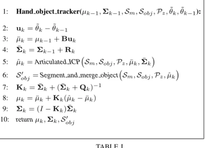
1: Hand object tracker(µk−1,Σk−1,Sm,Sobj,Pz,θ˜k,θ˜k−1): 2: uk= ˜θk−θ˜k−1
3: µ¯k=µk−1+Buk
4: Σ¯k=Σk−1+Rk
5: µˆk=Articulated ICP!Sm,Sobj,Pz,µ¯k,Σ¯k"
6: S"
obj=Segment and merge object
! Sm,Sobj,Pz,µˆk" 7: Kk= ¯Σk+ ( ¯Σk+Qk)−1 8: µk= ¯µk+Kk(ˆµk−µ¯k) 9: Σk= (I−Kk) ¯Σk 10: returnµk,Σk,Sobj" TABLE I
KALMAN FILTER FOR JOINT MANIPULATOR AND OBJECT TRACKING.
The algorithm, shown in Table I, takes as input µk−1 and
Σk−1, the previous time mean and covariance. Additionally,
Sm and Sobj are surfel clouds representing the manipulator
and the object respectively. As we will explain in more detail below, surfels describe small patches on the surface of an object, thereby providing more information than pure point clouds. Initially, Sobj is empty since no model of the object
is available. θ˜k andθ˜k−1 are the joint angles reported by the
encoders of the manipulator.
As given in Step 2, the motion updateuk is based upon the
difference in reported joint angles since the previous timestep. The prediction step of the Kalman filter then generates the predicted state µ¯k in Step 3. The matrix B simply projects
the joint angle update into the higher dimensional space of the Kalman filter state. Associated with this update step is noise in the motion distributed according to the covariance matrix Rk
(Step 4). If the calibration and the object’s position relative to the palm are assumed fixed (that is, if the object is grasped firmly), then Rk will not contribute any new uncertainty to
those parts of the state. Alternatively, one may include those terms in Rk in order to compensate for movement of the
camera or the object inside the hand.
In Step 5, the function Articulated ICP matches the surfel models of the manipulator and object into the observed point cloud and returns an estimate, µˆk, of the state vector that
minimizes the mis-match between these clouds. Details of this algorithm are given in Section II-B.
Segment and merge object uses the output of Articu-lated ICPto extract points from the current measurement,Pz,
that belong to the object. To do so, it uses the ICP resultµˆkto
appropriately transform the manipulator surfel modelSm into
the correct joint angles and into the sensor’s reference frame. Sm is then used to identify points in Pz generated by the
manipulator via simple distance checking. After segmenting the remaining points inPz (which can be done by computing
connected components over the image grid, similar to [7]), the points belonging to the object in hand can be identified due to their physicalrelation to the end effector. This technique has the added benefit that it does not require a static background as many vision-based algorithms do. The resulting points are
then integrated into Sobj with update rules we will describe
in Section III.
Steps 7 through 9 are standard Kalman filter correction steps, where we take advantage of the fact thatArticulated ICP
already generates an estimate of the state, µˆk, thereby
al-lowing the simplified correction in Step 8. Qk represents
the uncertainty in the ICP result µˆk. While techniques do
exist for estimating this matrix (e.g. by using the Jacobian matrix of the error function), their estimates are based on the local neighborhood of the solution. If ICP finds only a local optimum, such estimates could drastically underestimate the degree to which the ICP solution is off. We therefore decided to setQk by hand.
B. Articulated ICP
We now describe the functionArticulated ICPused in Step 5 of the tracking algorithm. We begin with a review of the ICP algorithm for rigid objects. The input to ICP are two 3D point-clouds,Ps=#p1s, . . . , pMs
$
andPt=#p1t, . . . , pNt
$
. The goal is to find a transformation T∗ (3D rotation and translation) which aligns the point-clouds as follows:
T∗= argmin T M % i=1 min pjt∈Pt wi & & &T(pis)−p j t & & &2 (1)
To achieve this minimization, the ICP algorithm iterates between the inner minimization of finding correspondences and the outer minimization of finding the transformation minimizing the sum of squared residuals given the correspon-dences. Since ICP only converges to a local minimum, a good initialization forT is important.
In our context,Psis a combined model of the manipulator
and object, andPtcontains the current observation. As in [18,
15], the point clouds in our articulated ICP are related to ob-jects that consist of multiple links connected via revolutionary joints. Specifically, each pointpi
s∈ Ps has associated to it a
linkli in the robot’s manipulator and is specified in the local
coordinate system of that link. Given the set of joint angles,
θ, each linkli in the robot model has a unique transformation
TiW that maps its points into the reference frame of the depth
sensor. The object is treated as its own link, which has an offsetTobj from the palm frame. The goal of articulated ICP
is to solve for the following:
!θ, Tcalib, Tobj"∗= argmin
$θ,Tcalib,Tobj% (2) M % i=1 min pjt∈Ptwi & &
&TiW(!θ, Tcalib, Tobj")(pis)−p j t & & &2
We have found that the use of point-to-plane type error functions [3], correspondence weights based on agreement of normals, and correspondence distance thresholds can help the performance of articulated ICP. Using point-to-plane requires a non-linear optimizer, for which we use Levenberg-Marquardt. To efficiently compute the normals of the target cloud, we use local neighborhoods provided by the grid-structure of the data.
Fig. 3. Two grasps of the same object. With just a single grasp, the resulting object model will have holes. Between the two grasps, the entirety of the object is visible.
We compute the correspondence for a surfel using a KD-tree of the point cloud from the depth sensor. As in [25], another option is to simply project each surfel into the image plane and performing bilinear interpolation on the grid structure of the cloud to select corresponding points and normals. While faster, this approach struggles with long, thin objects that may be very close in physical space but do not overlap when projected into the image plane.
For each frame, we extract SIFT keypoints and match them into a cloud of previously seen keypoints on the object. We use RANSAC to ensure geometric consistency and then add these matches as fixed correspondences into our ICP error function. For these feature points, we use a point-to-point error function rather than point-to-plane because it provides a stronger constraint. When, for example, the view of the object consists entirely of a planar surface, the addition of SIFT features as point-to-point matches provides the necessary information to perform the correct within-plane sliding.
We found it beneficial to bias ICP toward the predicted estimate provided by the Kalman filter. For this, we introduce the Kalman filter state into ICP by adding an additional term to Equation 2 that reflects the state of the Kalman filter:
(x−µ)TΣ−1(x−µ). This bias term is particularly important
when there exist ambiguities in the degrees of freedom to adjust due to occlusion or limited field of view. This approach automatically gives preference to adjusting degrees of freedom with higher uncertainty. For example, if the object pose within the hand is fairly certain, matches on the object will result in adjusting the arm pose rather than the object transformation. As a result, holding an object in the hand can actually improve the estimate of the arm pose. It should also be noted that adding this prior has the potential to affect the performance of the Kalman filter. µˆk is supposed to be an independent
estimate of the true state, but our prior biases it toward the existing µ¯k.
C. Handling Multiple Grasps
We have so far assumed that modeling begins with the object in the manipulator, and at no time is it let go. In Section V-C we will discuss how to achieve this first grasp, but there is another issue as well. The robot’s manipulator will occlude parts of the object as shown in Fig. 3, so to get complete models, our algorithm must be able to handle changes in grasp location.
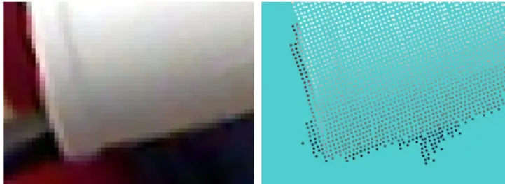
Fig. 4. One of the error modes of our depth sensor. Depicted here is a point cloud of the lip of a mug against a light blue background. Along both edges shown, extra depth points appear and are colored by the scene’s background. Additionally, the sensor has quantization errors and tends to fill in small holes.
An advantage of performing the object modeling using a robot is that the we have knowledge of when it will grasp or release. We use this knowledge to divide our tracking and modeling algorithm shown in Table I in to stages. These stages are: i) the typical object examination stage where the object is being manipulated away from the table’s surface; ii) raising the object from or lowering the object to the table; iii) grasping or releasing; and iv) object on the table.
Stage i is the only stage in which line 6, Segment and merge object, is performed. During this stage, there is a strong prior on the object remaining fixed within the manipulator. The object is transformed according the the transformation for the palm link, and the special object link is interpreted as an adjustment to that transformation. Stage ii proceeds exactly as stage i except that the model update is not performed because object segmentation becomes more difficult with other objects in close proximity. Stage iii is treated the same as stage ii except that the prior on object pose is loosened. When the robot grasps or releases an object, the object may move relative to the manipulator. Also possible is that the grasp may fail, and the object could drop. We do not yet address this type of event, but it is clearly a distinct possibility and one worth planning for.
Stage iv is different in that the object is not expected to move with the manipulator. The prior is for the object to remain fixed relative to the robot’s base. The object pose is not changed as the manipulator moves, and the pose adjustment term is reinterpreted to mean an adjustment relative to the robot’s base, not to the manipulator. The combination of these four stages allows the robot to examine an object using one grasp, put the object down, regrasp it, and examine it again, thereby filling in holes from the first grasp. In Section V, we demonstrate an example of a model built from multiple grasps.
III. OBJECTMODELING
We now describe the representation underlying our object models and the key steps involved in updating object models based on new data.
A. Surfels
Our choice of surfels [9, 25] as a representation was strongly influenced by the constraints of our problem. Our depth sensor, while versatile, does suffer from certain types of noise. In particular, we must be able to compensate for quantization
errors, filling in of holes, and expansion of objects by extra pixels. An example is shown in Fig. 4. Therefore, it is crucial that we be able to revise the models not just by adding points but also by keeping running estimates of their locations and by removing spurious points.
Additionally, the problem at hand involves tracking the robot’s manipulator, some of which may be occluded by the object or itself. We wish to be able to reason explicitly about the visibility of any particular point inSm orSobj before
as-signing it a correspondence. In doing so, we prevent irrelevant model points from negatively impacting the alignment.
Surfels fit all of these requirements and are very easy to work with. As we explain below, the addition, update, and removal rules for surfels are quite simple and robust. While other representations such as triangle meshes could provide the occlusion information we need, the update rules can be substantially more inefficient because of the need to maintain explicit connections with other vertices. Surfels, on the other hand, can be updated independently of each other and if desired can be later converted to a mesh in a post-processing step.
A surfel is essentially a circular surface patch. The prop-erties of a surfel si include its position, pi, its normal, ni,
and its radius,ri. The radius, as described in [25], is set such
that as viewed from the camera position, it would fill up the area of one pixel. As the camera gets closer to the surface, surfels are automatically resized, providing an elegant means for selecting the appropriate resolution, and further, for using varying levels of detail across a single surface.
One can associate additional attributes to surfels such as “visibility confidence” ci. The possible viewing angles of a
surfel are divided into 64 bins. The confidence is the number of such bins from which the surfel has been seen at least once. This provides a better measure of confidence than simply the number of frames in which a surfel has been seen because a patch seen from the same angle may consistently produce the same faulty reading. For visualization purposes, we also keep track of the color of the surfel using the frame that has the most perpendicular viewing angle onto the surfel.
B. Model update
After performing the segmentation described in Section II, we use surfel update rules similar to [25] to modify the object modelSobj. Each surfel locationpiis projected into the image
plane. We then use bilinear interpolation to determine the point p∗i and normaln∗i at that same location in the sensor reading.
pihas a depthdiandp∗i has a depthd∗i; the differencedi−d∗i is
used to determine the update rule that is used. In the following rules, we will say that a sensor reading p∗i is a valid object
reading if its surrounding pixels are in a single object segment, and n∗
i does not deviate from the camera direction by more
thanθmax.
1) |di−d∗i| ≤ dmax: If p∗i is a valid object reading and
ni does not deviate from the camera direction by more
than θmax, then the surfel is updated. This is done
and normal and updating the grid of viewing directions. Additionally, if the new measurement was taken from a closer location, then the radius of the surfel is updated accordingly. If the conditions do not hold, then we do nothing.
2) di−d∗i <−dmax: In this case, the observed point is
behind the surfel. If the surfel confidence ci is below
chigh, then the existing surfel is considered an outlier
and removed. It is replaced by a new one at p∗
i if that
is a valid object reading. Ifci is at leastchigh, then the
reading is considered an outlier and is ignored.
3) di−d∗i > dmax: Then the observed point is in front
of the model surfel si. As suggested by [25] we look
to find a surfel that occludessi. If we find one and its
confidence is at leastchigh andci is below chigh, then
siis removed. This is meant to remove surfels that have
been erroneously placed in the interior of an object. If no occluding surfel is found, we do nothing.
After surfel update comes the surfel addition step. For each pixel in the object segments, a new surfel is added if there are no existing surfels with normals toward the camera either in front of or close behind the reading. This is a simple heuristic; however, it allows us to acquire models of objects which have two surfaces close together such as the inside and outside of a coffee mug. Finally, there is one more removal step. Any surfel withci< cstarvethat has not been seen within the last
tstarve frames is removed. This is very effective at removing
erroneous surfels without the need to return to a viewing angle capable of observing the surfel patch. More details on the parameters in this approach and reasonable values for them can be found in [25].
IV. RELATED WORK
The existing work in tracking and modeling address subsets of the problem we are trying to solve; however, no one paper addresses them all. We make use of depth, visual, and encoder information to provide a tracking and modeling solution for enabling active object exploration for personal robotics.
A number of techniques exist for hand-tracking; however, many of these make use of only 2D information such as silhouettes and edge detections [1, 22]. Some require pre-computed databases and may only detect configurations within that database [1] and others are far from real-time algorithms. Given that we are using 3D sensors and that we wish to track the hand in real time through a continuous space of joint angles, such approaches are unsuitable.
Articulated ICP has been used in tracking applications in the past [18, 15]. However, to the best of our knowledge, it has not been integrated with Kalman filters, which provide the advantages of smoothing and estimating uncertainties. These uncertainties are crucial as they can be fed back into ICP to reflect the accumulated knowledge of the state. Building models of held objects and utilizing them during ICP is also a novel contribution of our algorithm and one which reinforces the need for the Kalman filter.
Typically, object tracking algorithms only rely on the use of visual data or depth data but not both, and to our knowledge none explicitly try to track the hand as a means of improving alignment. In the case of ProFORMA [17], the goal is to acquire and track models via webcam. While visual features alone work fine for some objects, many everyday objects lack sufficient texture for this type of tracking. Additionally, Pro-FORMA uses a different surface representation more suitable to the sparse point clouds produced by structure from motion. Weise et al. [25] use 3D range scans and model objects using surfels [9] but rely solely on object ICP with projection-based correspondences to provide alignment. They also demonstrate a potentially very useful online loop-closure algorithm. Loop-closure is an issue we have not addressed in this paper but which we plan to implement as future work. This work does not address the issue of hand tracking, an aspect which improves robustness to object symmetries and lack of texture. Kraft et al. [11] model contours of objects using a robotic manipulator and a stereo camera. The representations they learn, however, are not full surface models but rather sparse sets of oriented 3D points along contours. Another important difference is that the authors assume precise camera to robot calibration and precisely known robot state at all times. We believe these assumptions to be too restrictive for the technique to be of any widespread use.
Also related is the work by Ude et al. on robotic object recognition [24]. Their approach involves generating motion sequences to achieve varied views of an object, segmenting the object from images, and extracting training examples for a vision-based classifier. Unlike Kraft’s work, this paper assumes neither known camera calibration nor precisely known joint angles. While they do not perform tracking or surface mod-eling, their techniques for selecting arm motions may prove useful for our goals as well.
For the graphics community, obtaining accurate 3D shapes of objects is a primary research objective and has been exten-sively studied. Many researchers have applied range sensing of various kinds (e.g. [6, 16]) and can recover amazing details by combining meticulous experimental setup with sophisticated geometric inference algorithms, such as that in the Digital Michelangelo Project [13]. In comparison, although we are recovering both object shape and appearance, our objective is not photorealistic rendering, but to robustly and efficiently model objects from an autonomous robot, with an affordable sensor, and to apply such object knowledge in recognition and manipulation.
V. EXPERIMENTS
The robot used in our experiments is shown in Fig. 1. The basic setup consists of a WAM Arm and BarrettHand mounted on a Segway. The depth camera is located to the side and above the robot manipulator so as to provide a good view of the manipulator workspace. The specific depth camera we use was mainly developed for gaming and entertainment applications. It provides pixel colors and depth values at 640x480 resolution, at 30 frames per second.
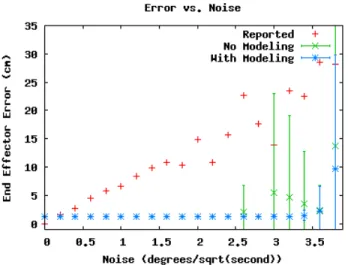
Fig. 5. Distance of the end effector from the ground truth as a function of the per joint angle drift rate. Notice that the tracking error does not increase with noise until at least 2.4◦/√s, and when modeling the object, failures do not begin until 3.4◦/√s.
We collected depth camera data and joint angle sequences of the moving system. In all but the last experiments, the manipulator grasps and trajectories were specified manually and the objects were grasped only once. Techniques like those described by Ude et al. [24] may be useful for automatic generation of optimized motion trajectories. Using multiple grasps to generate complete object models is discussed briefly in Section V-C.
Our current implementation of the algorithm described in Section II-A runs at 1 to 2 frames per second. We are confident that the update rate of the system can be increased to 10 frames per second using a more optimized implementation and taking advantage of GPU hardware. To simulate such a higher update rate, we played back the datasets at approximately one fifth of the real time. We have found that by skipping frames, we are able to operate in real time, but the resulting models are not as detailed.
A. Joint Manipulator and Object Tracking
In this experiment, we evaluate the ability of our technique to track the position of the robot hand. Specifically, we investigate if our system would enable accurate tracking of a low cost manipulator equipped with position feedback far less accurate than that of the WAM arm. To do so, we use the WAM controller’s reported angles as ground truth. Though these angles are far from perfect, they provide a common comparison point for the different noise settings. To simulate an arm with greater inaccuracies, we included normally distributed additive noise of varying magnitude.
To provide an intuitive feel for the units involved, we show in Fig. 6 an example of the deviation between reported and observed manipulator after 20 seconds of motion at a 2.0◦/√s noise level. In Fig. 5, we demonstrate that our tracking algorithm can handle large amounts of noise in the reported angles without losing accuracy in tracking the end effector. In this experiment, the hand was grasping a coffee
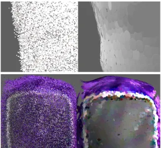
Fig. 6. (left) Drift resulting from 2.0◦/√snoise. Actual sensor data in true color, tracking result in red, and noisy joint angles in blue. (right) Surfel model produced at this level of noise.
Fig. 7. Shown here are a can and a mug aligned with ICP alone on the left and our algorithm on the right. Due to the high level of symmetry in these objects, ICP is unable to find the correct alignments between depth scans, resulting in useless object models.
mug. Red dots in Fig. 5 show errors for the uncorrected, noisy pose estimates. Green dots, along with 95% confidence intervals, show tracking results when ignoring the object in the robot’s hand. Blue dots are results for our joint tracking approach, when modeling the object and tracking it along with the manipulator. Each dot represents the end effector positioning error at the end of the tracking sequence, averaged over multiple runs and multiple arm motions. As can be seen, modeling the object further increases the robustness to noise. This is because we can both explicitly reason about the modeled object occluding the fingers and use the object as an additional surface to match.
An example model generated for the coffee mug under high noise conditions is shown in Fig. 6. When comparing this model to one built without additional noise (see Fig. 7), it becomes apparent that our approach successfully compensates for motion noise. We have also begun experiments on ignoring encoders entirely and adding inaccuracies to the kinematic model. Initial tests suggest robustness to these factors as well, but a more thorough evaluation is needed.
B. Object Modeling
In this set of experiments we investigate different aspects of the tracking and object modeling technique.
Many objects in everyday environments exhibit rotational symmetries or are lacking in distinctive geometries for match-ing. Many existing object modeling algorithms such as [25] rely on being able to geometrically match the object model into the new frame. To demonstrate the advantage of also tracking the manipulator, we show in Fig. 7 how object ICP alone
Fig. 8. Comparison between aggregated point clouds and surfel models generated from the same data and the same frame alignments.
performs on two highly symmetric objects.
In this experiment, object segmentations from the joint ICP were used to produce clouds to be registered, but ICP was left to align the object points without any information about the hand motion. As can be seen in Fig. 7, ICP is unable to recover the proper transformations because of the ambiguity in surface matching. It should also be noted that for the mug case in particular, systems like ProFORMA [17], which rely on tracking visual features would also be incapable of tracking or modeling the object.
We have also found that surfels are a very compact and elegant solution to maintaining object models. Besides the benefits of occlusion-checking and incremental update, multi-ple measurements can be merged into a single surfel, and the arrangement is cleaner and more visually appealing.
Fig. 8 illustrates the difference between raw data point clouds and surfel models. Shown on the right are the surfel patches belonging to two separate objects. The two panels on the left show the raw, colored point clouds from which the surfels were generated. The raw clouds contained on the order of one million points and were randomly downsampled for visualization purposes. The surfel clouds contain on the order of ten thousand surfels.
The surfel models we have obtained in our online process contain accurate information of both surface positions and normals, and can be readily used in a post-processing step, through meshing and coloring, to improve the qualities of the shape and visual appearance. We use the open-source Meshlab software and follow a number of standard steps: first we apply the Poisson Reconstruction algorithm [10], with a level of12, to obtain a surface mesh from the oriented point cloud. Second, we apply the Catmull-Clark subdivision to refine the mesh. Third, we reproject the oriented points to the original frames, and assign vertex colors there. We use the frame that has the most frontal view of a particular vertex, unless it fails to pass a simple color saturation threshold check.
Fig. 9. Triangulated surface models constructed from surfel clouds. On the top is a Matlab box and on the bottom a stuffed doll. Any large holes are due to occlusion by the hand.
Fig. 10. (left) A model of a can constructed using only the first grasp from Fig. 3. Notice the large holes where the hand occludes the view. (right) The same model after the second grasp.
A few of the reconstructed objects are shown in Fig. 9. For rendered videos of the models and videos demonstrating the arm tracking and surfel model construction, see www. youtube.com/UWObjectModeling.
C. Toward Autonomous Object Modeling
To perform autonomous grasping and modeling, we im-plemented an approach that enables the robot to pick up an unknown object. The object grasp point and approach direction are determined by first subtracting the object from the table plane using the depth camera data, and then computing the principal component of the point cloud representing the object. The approach is then performed orthogonal to this principal component. While this technique is not intended as a general grasping approach, it worked well enough to perform our initial experiments. Alternatively, one can use local visual or geometric features as in [20] to obtain this first grasp.
The model can be improved by allowing the robot to place the object back down and regrasp it. We demonstrate this in Fig. 10. While Section II details how the tracking and modeling can be made to work with regrasping, the best way to generate the second grasp is still unclear. Although the first grasp must be made heuristically due to lack of knowledge about the object, the second grasp can be informed by the mostly complete surfel model. The model can be passed along to a grasp planner (e.g. [2, 14]) but should be done in a way that discourages grasps covering previously unseen areas.
One option is to incorporate into the grasp quality metric an estimate of the area of overlap between the two grasps.
VI. CONCLUSIONS AND FUTURE WORKS We developed an algorithm for tracking robotic manipula-tors and modeling grasped objects using depth cameras. Our approach performs tracking, robot to sensor calibration, and object modeling all in one Kalman filter based framework. Experiments show that the technique can robustly track a manipulator even when significant noise is imposed on the po-sition feedback provided by the manipulator. The experiments also show that jointly tracking the hand and the object grasped by the hand further increases the robustness of the approach. The insight behind this technique is that even though an object might occlude the robot hand, the object itself can serve as guidance for the pose estimate.
We also introduced a tight integration of the tracking algorithm and an object modeling approach. Our technique uses the Kalman filter estimate to initially locate the object and to incorporate new observations into the object model. We use surfels as the key representation underlying the object and manipulator models. This way, our approach can do occlusion-based outlier rejection and adapt the resolution of the representation to the quality of the available data.
An approach alternative to ours could be to generate an object model by moving a camera around the object. However, this approach cannot provide information about object parts that are not visible based on the object’s position in the environment. Furthermore, our approach of investigating an object in the robot’s hand also lends itself to extracting information about the object’s weight and surface properties.
Our key motivation for this work is in enabling robots to actively investigate objects in order to acquire rich models for future use. Toward this goal, several open research questions need to be addressed. We have discussed possible techniques for initial and subsequent grasp generation, but these problems remain as future work. There is also the problem of automatic trajectory generation for quick coverage of the object. Further-more, the overall spatial and visual consistency of objects can be further improved by adding loop closure techniques, similar to SLAM mapping [23]. Finally, by attaching visual features and grasp information to our object models, a robot could use such models to quickly detect them in the environment using a technique similar to the work of Collet et al. [5] and grasp the objects again.
ACKNOWLEDGEMENTS
We would like to thank Brian Mayton for all of his assis-tance, including generating and executing suitable grasps and arm trajectories for our experiments. We would also like to thank Peter Brook for allowing us to incorporate his heuristic grasp planner into our system.
REFERENCES
[1] V. Athitsos and S. Sclaroff, “Estimating 3d hand pose from a cluttered image,” Computer Vision and Pattern Recognition, IEEE Computer Society Conference on, vol. 2, p. 432, 2003.
[2] D. Berenson and S. Srinivasa, “Grasp synthesis in cluttered environments for dexterous hands,” inProc. of the IEEE-RAS International Conference on Humanoid Robots (Humanoids), 2008.
[3] Y. Chen and G. Medioni, “Object modelling by registration of multiple range images,”Image Vision Comput., vol. 10, no. 3, pp. 145–155, 1992. [4] M. Ciocarlie, C. Goldfeder, and P. Allen, “Dimensionality reduction for hand-independent dexterous robotic grasping,” inProc. of the IEEE/RSJ International Conference on Intelligent Robots and Systems (IROS), 2007.
[5] A. Collet Romea, D. Berenson, S. Srinivasa, and D. Ferguson, “Object recognition and full pose registration from a single image for robotic ma-nipulation,” inProc. of the IEEE International Conference on Robotics & Automation (ICRA), 2009.
[6] B. Curless and M. Levoy, “A volumetric method for building complex models from range images,” inACM Transactions on Graphics (Proc. of SIGGRAPH), 1996.
[7] P. F. Felzenszwalb and D. P. Huttenlocher, “Efficient graph-based image segmentation,”Int. J. Comput. Vision, vol. 59, no. 2, pp. 167–181, 2004. [8] J. Glover, D. Rus, and N. Roy, “Probabilistic models of object geometry with application to grasping,” in International Journal of Robotics Research (IJRR), vol. 28, no. 8, 2009.
[9] M. Habbecke and L. Kobbelt, “A surface-growing approach to multi-view stereo reconstruction,” inCVPR, 2007.
[10] M. Kazhdan, M. Bolitho, and H. Hoppe, “Poisson surface reconstruc-tion,” inSymposium on Geometry Processing, 2006.
[11] D. Kraft, N. Pugeault, E. Baseski, M. Popovic, D. Kragic, S. Kalkan, F. Wrgtter, and N. Krger, “Birth of the object: Detection of objectness and extraction of object shape through object-action complexes.”I. J. Humanoid Robotics, vol. 5, no. 2, pp. 247–265, 2008.
[12] K. Lai and D. Fox, “3D laser scan classification using web data and domain adaptation,” inProc. of Robotics: Science and Systems (RSS), 2009.
[13] M. Levoy, K. Pulli, B. Curless, S. Rusinkiewicz, D. Koller, L. Pereira, M. Ginzton, S. Anderson, J. Davis, J. Ginsberg, J. Shade, and D. Fulk, “The digital michelangelo project: 3d scanning of large statues,” in SIGGRAPH, 2000.
[14] A. T. Miller and A. T. Miller, “Graspit!: A versatile simulator for robotic grasping,”IEEE Robotics and Automation Magazine, vol. 11, pp. 110– 122, 2004.
[15] L. M¨undermann, S. Corazza, and T. P. Andriacchi, “Accurately measur-ing human movement usmeasur-ing articulated icp with soft-joint constraints and a repository of articulated models,” inProc. of the IEEE Computer So-ciety Conference on Computer Vision and Pattern Recognition (CVPR), 2007.
[16] D. Pai, K. van den Doel, D. James, J. Lang, J. Lloyd, J. Richmond, and S. Yau, “Scanning physical interaction behavior of 3d objects,” inACM Transactions on Graphics (Proc. of SIGGRAPH), 2001, pp. 87–96. [17] Q. Pan, G. Reitmayr, and T. Drummond, “ProFORMA: Probabilistic
Feature-based On-line Rapid Model Acquisition,” inProc. 20th British Machine Vision Conference (BMVC), London, September 2009. [18] S. Pellegrini, K. Schindler, , and D. Nardi, “A generalization of the icp
algorithm for articulated bodies,” inBritish Machine Vision Conference (BMVC’08), M. Everingham and C. Needham, Eds., September 2008. [19] B. Rasolzadeh, M. Bjorkman, K. Huebner, and D. Kragic, “An active
vision system for detecting, fixating and manipulating objects in real world,” inInternational Journal of Robotics Research (IJRR), 2009. [20] A. Saxena, J. Driemeyer, and A. Ng, “Robotic grasping of novel
objects using vision,”International Journal of Robotics Research (IJRR), vol. 27, no. 2, 2008.
[21] J. Sturm, C. Plagemann, and W. Burgard, “Body schema learn-ing for robotic manipulators from visual self-perception,” Journal of Physiology-Paris, vol. 103, no. 3-5, pp. 220 – 231, 2009, neurorobotics. [22] E. B. Sudderth, M. I. Mandel, W. T. Freeman, and A. S. Willsky, “Visual hand tracking using nonparametric belief propagation,”Computer Vision and Pattern Recognition Workshop, vol. 12, p. 189, 2004.
[23] S. Thrun, W. Burgard, and D. Fox,Probabilistic Robotics. Cambridge, MA: MIT Press, September 2005, iSBN 0-262-20162-3.
[24] A. Ude, D. Omrcen, and G. Cheng, “Making object learning and recognition an active process,”I. J. Humanoid Robotics, vol. 5, no. 2, pp. 267–286, 2008.
[25] T. Weise, T. Wismer, B. Leibe, , and L. V. Gool, “In-hand scanning with online loop closure,” inIEEE International Workshop on 3-D Digital Imaging and Modeling, October 2009.