2
Defense Acquisition Guidebook ANNEX
TEST AND EVALUATION MASTER PLAN FOR
PROGRAM TITLE/SYSTEM NAME ACRONYM ACAT Level Program Elements Xxxxx ************************************************************************ SUBMITTED BY ____________________________________________________ ____________
Program Manager DATE
CONCURRENCE
____________________________________________________ ____________
Program Executive Officer DATE
or Developing Agency (if not under the Program Executive Officer structure)
____________________________________________________ ____________
Operational Test Agency DATE
____________________________________________________ ____________
User's Representative DATE
DoD COMPONENT APPROVAL
____________________________________________________ ____________
DoD Component Test and Evaluation Director DATE
____________________________________________________ ____________ DoD Component Acquisition Executive (Acquisition Category I) DATE Milestone Decision Authority (for less-than-Acquisition Category I)
Note: For Joint/Multi Service or Agency Programs, each Service or Defense Agency should provide a signature page for parallel staffing through its CAE or Director, and a separate page should be provided for OSD Approval
************************************************************************ OSD APPROVAL ____________________________________________________ ____________ ODUSD(A&T)/DDT&E DATE ____________________________________________________ ____________ D,OT&E DATE
3 TABLE OF CONTENTS PART 1 – INTRODUCTION ... 1.1 PURPOSE ... 1.2 MISSION DESCRIPTION ... 1.3 SYSTEM DESCRIPTION ... 1.3.1 System Threat Assessment ... 1.3.2 Program Background ... 1.3.2.1 Previous Testing ... 1.3.3 Key Capabilities ... 1.3.3.1 Key Interfaces ...
1.3.3.2 Special Test or Certification Requirements ... 1.3.3.3 Systems Engineering (SE) Requirements ... PART II – TEST PROGRAM MANAGEMENT AND SCHEDULE ...
2.1 T&E MANAGEMENT ... 2.1.1 T&E Organizational Construct ... 2.2 COMMON T&E DATA BASE REQUIREMENTS ... 2.3 DEFICIENCY REPORTING ... 2.4 TEMP UPDATES ... 2.5 INTEGRATED TEST PROGRAM SCHEDULE ...
Figure 2.1 – Integrated Test Program Schedule (Modified) ...
PART III – TEST AND EVALUATION STRATEGY ... 3.1 T&E STRATEGY ... 3.2 EVALUATION FRAMEWORK ...
Reliability Growth(Moved from Section 3.8) ...
Design of Experiments(New Section) ... Figure 3.1 – Top-Level Evaluation Framework Matrix ... 3.3 DEVELOPMENTAL EVALUATION APPROACH ... 3.3.1. Mission-Oriented Approach. ... 3.3.2 Developmental Test Objectives ... 3.3.3 Modeling and Simulation ...
4
3.3.4. Test Limitations... 3.4 LIVE FIRE EVALUATION APPROACH ... 3.4.1 Live Fire Test Objectives ... 3.4.2 Modeling and Simulation ... 3.4.3 Test Limitations... 3.5 CERTIFICATION FOR IOT&E...
3.5.1 Assessment of Operational Test Readiness ...
3.6 OPERATIONAL EVALUATION APPROACH ...
3.6.1 Operational Test Objectives ... 3.6.2 Modeling and Simulation ... 3.6.3 Test Limitations... 3.7 OTHER CERTIFICATIONS ... 3.8 DESIGN OF EXPERIMENTS ... 3.9 FUTURE TEST AND EVALUATION ... PART IV – RESOURCE SUMMARY ...
4.1 INTRODUCTION ... 4.1.1 Test Articles ... 4.1.2 Test Sites and Instrumentation ... 4.1.3 Test Support Equipment ... 4.1.4 Threat Representation ... 4.1.5 Test Targets and Expendables ... 4.1.6 Operational Force Test Support ... 4.1.7 Models, Simulations, and Test-Beds ... 4.1.8 Joint Operational Test Environment ... 4.1.9 Special Requirements... 4.2 FEDERAL, STATE, LOCAL REQUIREMENTS ... 4.3 MANPOWER/PERSONNEL TRAINING ... 4.4 TEST FUNDING SUMMARY... Table 4.1 Resource Summary Matrix
APPENDIX A – BIBLIOGRAPHY APPENDIX B – ACRONYMS
APPENDIX C – POINTS OF CONTACT APPENDIX D – DESIGN OF EXPERIMENTS
5
1. PART I - INTRODUCTION
1.1. Purpose. State the purpose of the Test and Evaluation Master Plan (TEMP). Identify if this is an initial or updated TEMP. State the Milestone (or other)
decision the TEMP supports. Reference and provide hyperlinks to the documentation initiating the TEMP (i.e., Initial Capability Document (ICD), Capability Development Document (CDD), Capability Production Document (CPD), Acquisition Program Baseline (APB), Acquisition Strategy Report (ASR), Concept of Operations (CONOPS)). State the Acquisition Category (ACAT) level, operating command(s), and if listed on the OSD T&E Oversight List (actual or projected).
1.2. Mission Description. Briefly summarize the mission need described in the program capability requirements documents in terms of the capability it will provide to the Joint Forces Commander. Describe the mission to be
accomplished by a unit equipped with the system using all applicable CONOPS and Concepts of Employment. Incorporate an OV-1 of the system showing the intended operational environment. Also include the organization in which the system will be integrated as well as significant points from the Life Cycle
Sustainment Plan, the Information Support Plan, and Program Protection Plan. Provide links to each document referenced in the introduction. For business systems, include a summary of the business case analysis for the program. 1.3. System Description. Describe the system configuration. Identify key features and subsystems, both hardware and software (such as architecture, system and user interfaces, security levels, and reserves) for the planned increments within the Future Years Defense Program (FYDP).
1.3.1. System Threat Assessment. Succinctly summarize the threat environment (to include cyber-threats) in which the system will operate. Reference the appropriate DIA or component-validated threat documents for the system.
1.3.2. Program Background. Reference the Analysis of Alternatives (AoA), the APB and the materiel development decision to provide background information on the proposed system. Briefly describe the overarching Acquisition Strategy (for space systems, the Integrated Program Summary (IPS)), and the
Technology Development Strategy (TDS). Address whether the system will be procured using an incremental development strategy or a single step to full capability. If it is an evolutionary acquisition strategy, briefly discuss planned upgrades, additional features and expanded capabilities of follow-on increments. The main focus must be on the current increment with brief descriptions of the previous and follow-on increments to establish continuity between known increments.
1.3.2.1. Previous Testing. Discuss the results of any previous tests that apply to, or have an effect on, the test strategy.
1.3.3. Key Capabilities. Identify the Key Performance Parameters (KPPs) and Key System Attributes (KSAs) for the system. For each listed parameter, provide the threshold and objective values from the CDD/CPD and reference the
paragraph. Information Assurance (Cybersecurity) Guidance Examples for ¶ 1.3.1 Threat Representation Guidance Example for ¶ 1.3.1
6
1.3.3.1. Key Interfaces. Identify interfaces with existing or planned systems’ architectures that are required for mission accomplishment. Address integration and modifications needed for commercial items. Include interoperability with existing and/or planned systems of other Department of Defense (DoD) Components, other Government agencies, or Allies. Provide a diagram of the appropriate DoD Architectural Framework (DoDAF) system operational view from the CDD or CPD.
1.3.3.2. Special test or certification requirements. Identify unique system characteristics or support concepts that will generate special test, analysis, and evaluation requirements (e.g., security test and evaluation and Information Assurance (IA) (Cybersecurity) Certification and Accreditation (C&A), post deployment software support, resistance to chemical, biological, nuclear, and radiological effects; resistance to countermeasures; resistance to reverse engineering/exploitation efforts (Anti-Tamper); development of new threat
simulation, simulators, or targets.
1.3.3.3. Systems Engineering (SE) Requirements. Reference all SE-based information that will be used to provide additional system evaluation targets driving system development. Examples could include hardware reliability growth
sand software maturity growth strategies. The SEP should be referenced in this section and aligned to the TEMP with respect to SE Processes, methods, and tools identified for use during T&E.
Information Assurance (Cybersecurity) Guidance Examples for ¶ 1.3.3.2 Threat Representation Guidance Example for ¶ 1.3.3.3
7
2. PART II – TEST PROGRAM MANAGEMENT AND SCHEDULE
2.1 T&E Management. Discuss the test and evaluation responsibilities of all participating organizations (such as developers, testers, evaluators, and users). Describe the role of contractor testing in early system development. Describe the role of government developmental testers to assess and evaluate system performance. Describe the role of the Operational Test Agency (OTA)
/operational testers to confirm operational effectiveness, operational suitability and survivability.
2.1.1. T&E Organizational Construct. Identify the organizations or activities (such as the T&E Working-level Integrated Product Team (WIPT) or Service equivalent, LFT&E IPT, etc.) in the T&E management structure, to include the sub-work groups, such as a modeling & simulation, or reliability. Provide sufficient
information to adequately understand the functional relationships. Reference the T&E WIPT charter that includes specific responsibilities and deliverable items for detailed explanation of T&E management. These items include TEMPs and Test Resource Plans (TRPs) that are produced collaboratively by member
organizations.
2.2. Common T&E Database Requirements. Describe the requirements for and methods of collecting, validating, and sharing data as it becomes available from the contractor, Developmental Test (DT), Operational Test (OT), and oversight organizations, as well as supporting related activities that contribute or use test data (e.g., information assurance (Cybersecurity) C&A, interoperability
certification, etc.). Describe how the pedigree of the data will be established and maintained. The pedigree of the data refers to understanding the configuration of the test asset, and the actual test conditions under which the data were obtained for each piece of data. State who will be responsible for maintaining this data. 2.3. Deficiency Reporting. Briefly describe the processes for documenting and tracking deficiencies identified during system development and testing. Describe how the information is accessed and shared across the program. The processes should address problems or deficiencies identified during both contractor and government test activities. The processes should also include issues that have not been formally documented as a deficiency (e.g., watch items).
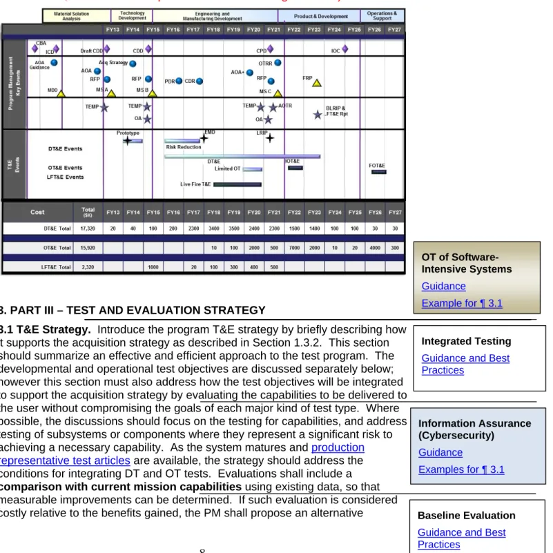
2.4. TEMP updates. Reference instructions for complying with DoDI 5000.02 required updates or identify exceptions to those procedures if determined necessary for more efficient administration of document. Provide guidelines for keeping TEMP information current between updates. For a Joint or Multi-Service TEMP, identify references that will be followed or exceptions as necessary. 2.5. Integrated Test Program Schedule. Display (see Figure 2.1) the overall time sequencing of the major acquisition phases and milestones (as necessary, use the NSS-03-01 time sequencing). Include the test and evaluation major decision points, related activities, and planned cumulative funding expenditures by appropriation by year. Include event dates such as major decision points as defined in DoD Instruction 5000.02, e.g., operational assessments, preliminary and critical design reviews, test article availability; software version releases; appropriate phases of DT&E; LFT&E; Joint Interoperability Test Command (JITC) interoperability testing and certification date to support the MS-C and Full-Rate Production (FRP) Decision Review (DR). Include significant Information
Assurance (Cybersecurity) certification and accreditation event sequencing, such
Integrated Test Program Schedule Guidance
8
as Interim Authorization to Test (IATT), Interim Authorization to Operate (IATO) and Authorization to Operate (ATO). Also include operational test and
evaluation; Low-Rate Initial Production (LRIP) deliveries; Initial Operational Capability (IOC); Full Operational Capability (FOC); and statutorily required reports such as the Live-Fire T&E Report and Beyond Low-Rate Initial Production (B-LRIP) Report. Provide a single schedule for multi-DoD
Component or Joint and Capstone TEMPs showing all related DoD Component system event dates.
Figure 2.1 SAMPLE Integrated Program Test Schedule (Click on the example schedule to see a larger version)
3. PART III – TEST AND EVALUATION STRATEGY
3.1 T&E Strategy. Introduce the program T&E strategy by briefly describing how it supports the acquisition strategy as described in Section 1.3.2. This section should summarize an effective and efficient approach to the test program. The developmental and operational test objectives are discussed separately below; however this section must also address how the test objectives will be integrated to support the acquisition strategy by evaluating the capabilities to be delivered to the user without compromising the goals of each major kind of test type. Where possible, the discussions should focus on the testing for capabilities, and address testing of subsystems or components where they represent a significant risk to achieving a necessary capability. As the system matures and production
representative test articles are available, the strategy should address the
conditions for integrating DT and OT tests. Evaluations shall include a comparison with current mission capabilities using existing data, so that measurable improvements can be determined. If such evaluation is considered
costly relative to the benefits gained, the PM shall propose an alternative Baseline Evaluation Guidance and Best Practices Information Assurance (Cybersecurity) Guidance Examples for ¶ 3.1 Integrated Testing Guidance and Best Practices
OT of Software-Intensive Systems Guidance
9
evaluation strategy. Describe the strategy for achieving this comparison and for ensuring data are retained and managed for future comparison results of
evolutionary increments or future replacement capabilities. To present the program’s T&E strategy, briefly describe the relative emphasis on methodologies (e.g., Modeling and Simulation (M&S), Measurement Facility (MF), Systems
Integration Laboratory (SIL), Hardware-In-the-Loop Test (HILT), Installed System Test Facility (ISTF), Open Air Range (OAR)).
3.2. Evaluation Framework. Describe the overall evaluation approach focusing on key decisions in the system lifecycle and addressing key system risks, program unique Critical Operational Issues (COIs) or Critical Operational Issue Criteria (COIC), and Critical Technical Parameters (CTPs). Specific areas of evaluation to address are related to the:
(1) Development of the system and processes (include maturation of system design)
(2) System performance in the mission context
(3) OTA independent assessments and evaluations
(4) Survivability and/or lethality
(5) Comparison with existing capabilities, and (6) Maturation of highest risk technologies
(7) Reliability Growth This paragraph has been moved forward from paragraph 3.8 of the DAG guidebook. Reliability growth should be integrated into the T&E strategy and explained as part of the Evaluation Framework.
Since reliability is a driver during system development, identify, in tabular form, the amount of operating time being accrued during the each of the tests listed in the Figure 2.1. Table should contain the system
configuration, operational concept, etc. Reference and provide hyperlinks to the reliability growth planning document. (Moved from Para 3.8)
(8) Design of Experiments. This is a new paragraph added to the DAG guidebook. Design of Experiments is integral to the Evaluation
Framework and begins with selection of evaluation metrics in Figure 3.1. In this paragraph, provide an overview of the experimental design and attach Appendix D, with the details of the design. See links at the right for general DOE guidance and examples.
Describe any related systems that will be included as part of the evaluation approach for the system under test (e.g., data transfer, information exchange
Mission-Focused Metrics Guidance Information Assurance (Cybersecurity) Guidance Examples for ¶ 3.2 DOE Guidance
TEMP Body Examples Precision Guided Weapon Example Appendix
Artillery Example Appendix Software Example Body and Appendix
Reliability Growth General Guidance
Reliability Growth Example Software Reliability
Tracking Example Ship-Specific Guidance New Ship Example Mature Ship Example
Integrated Survivability Assessment
10
requirements, interoperability requirements, and documentation systems). Also identify any configuration differences between the current system and the system to be fielded. Include mission impacts of the differences and the extent of
integration with other systems with which it must be interoperable or compatible. Describe how the system will be evaluated and the sources of the data for that evaluation. The discussion should address the key elements for the
evaluations, including major risks or limitations for a complete evaluation of the increment undergoing testing. The reader should be left with an understanding of the value-added of these evaluations in addressing both programmatic and warfighter decisions or concerns. This discussion provides rationale for the major test objectives and the resulting major resource requirements shown in Part IV - Resources.
Include a Top-LevelEvaluation Framework matrix that shows the correlation between the KPPs/KSAs, CTPs, key test measures (i.e., Measures of
Effectiveness (MOEs) and Measures of Suitability (MOSs)), planned test methods, and key test resources, facility or infrastructure needs. When
structured this way, the matrix should describe the most important relationships between the types of testing that will be conducted to evaluate the Joint
Capabilities Integration and Development System (JCIDS)-identified KPPs/KSAs, and the program’s CTPs. Figure 3.1 shows how the Evaluation Framework could be organized. Equivalent Service-specific formats that identify the same
relationships and information may also be used. The matrix may be inserted in Part III if short (less than one page), or as an annex. The evaluation framework matrix should mature as the system matures. Demonstrated values for
measures should be included as the acquisition program advances from milestone to milestone and as the TEMP is updated.
The suggested content of the evaluation matrix includes the following: • Key requirements & T&E measures – These are the KPPs and
KSAs and the top-level T&E issues and measures for evaluation. The top-level T&E issues would typically include COIs/Critical Operational Issues and Criteria (COICs), CTPs, and key MOEs/MOSs. System-of-Systems and technical review issues should also be included, either in the COI column or inserted as a new column. Each T&E issue and measure should be associated with one or more key requirements. However, there could be T&E measures without an associated key requirement or COI/COIC. Hence, some cells in figure 3.1 may be empty.
• Overview of test methodologies and key resources – These identify test methodologies or key resources necessary to generate data for evaluating the COIs/COICs, key requirements, and T&E measures. The content of this column should indicate the
methodologies/resources that will be required and short notes or pointers to indicate major T&E phases or resource names. M&S should be identified with the specific name or acronym.
• Decisions Supported – These are the major design, developmental, manufacturing, programmatic, acquisition, or employment decisions most affected by the knowledge obtained through T&E.
Evaluation of Software- Intensive Systems Evaluation Guidance Accuracy Evaluation Example
Data Restoral Evaluation Example
Timeliness Evaluation Case Study
11
Figure 3.1, Top-Level Evaluation Framework Matrix
Key Requirements and T&E Measures Test Methodologies/Key Resources (M&S, SIL, MF, ISTF, HITL, OAR)
Decision Supported Key Reqs COIs Key MOEs/ MOSs CTPs & Threshold KPP#1: COI #1. Is the XXX effective for…
MOE 1.1. Engine thrust Chamber measurement
Observation of performance profiles OAR
PDR CDR COI #2. Is the XXX suitable for… Data upload time
Component level replication
Stress and Spike testing in SIL PDR CDR COI #3. Can the
XXX be… MOS 2.1. MS-C FRP MOE 1.3. Post-CDR FRP MOE 1.4. Reliability based on growth curve
Component level stress testing Sample performance on growth curve
Sample performance with M&S augmentation
PDR CDR MS-C
KPP #2 MOS 2.4. Data link MS-C
SRR KPP #3 COI #4. Is
training….
MOE 1.2. Observation and Survey MS-C
FRP KSA #3.a COI #5. Documentation MOS 2.5. MS-C FRP Reliability Growth General Guidance Ship-Specific Guidance Example for Figure 3.1
12
3.3. Developmental Evaluation Approach. Describe the top-level approach to evaluate system and process maturity, as well as, system capabilities and limitations expected at acquisition milestones and decision review points. The discussion should include logistics, reliability growth, and system performance aspects. Within this section, also discuss:
1) rationale for CTPs (see below for a description of how to derive CTPs), 2) key system or process risks,
3) any certifications required (e.g. weapon safety, interoperability, spectrum approval, information assurance (Cybersecurity)),
4) any technology or subsystem that has not demonstrated the expected level of technology maturity at level 6 (or higher), system performance, or has not achieved the desired mission capabilities for this phase of
development,
5) degree to which system hardware and software design has stabilized so as to determine manufacturing and production decision uncertainties, 6) key issues and the scope for logistics and sustainment evaluations, and 7) reliability thresholds when the testing is supporting the system’s reliability
growth curve.
CTPs are measurable critical system characteristics that, if not achieved, preclude the fulfillment of desired operational performance capabilities. While not user requirements, CTPs are technical measures derived from desired user capabilities. Testers use CTPs as reliable indicators that the system is on (or behind) the planned development schedule or will likely (or not likely) achieve an operational capability. Limit the list of CTPs to those that support the COIs. Using the system specification as a reference, the chief engineer on the program should derive the CTPs to be assessed during development.
3.3.1. Mission-Oriented Approach. Describe the approach to evaluate the system performance in a mission context during development in order to influence the design, manage risk, and predict operational effectiveness and operational suitability. A mission context focuses on how the system will be employed. Describe the rationale for the COIs or COICs.
3.3.2. Developmental Test Objectives. Summarize the planned objectives and state the methodology to test the system attributes defined by the applicable capability requirement document (CDD, CPD, CONOPs) and the CTPs that will be addressed during each phase of DT as shown in Figure 3.1, Top-Level Evaluation Framework matrix and the Systems Engineering Plan.
Subparagraphs can be used to separate the discussion of each phase. For each DT phase, discuss the key test objectives to address both the contractor and government developmental test concerns and their importance to achieving the exit criteria for the next major program decision point. If a contractor is not yet selected, include the developmental test issues addressed in the Request For Proposals (RFPs) or Statement of Work (SOW). Discuss how developmental testing will reflect the expected operational environment to help ensure developmental testing is planned to integrate with operational testing. Also include key test objectives related to logistics testing. All objectives and CTPs should be traceable in the Top-Level Evaluation Framework matrix to ensure all KPPs/KSAs are addressed, and that the COIs/COICs can be fully answered in
Mission-Oriented Evaluation Guidance Examples Information Assurance (Cybersecurity) Guidance Example for ¶ 3.3 Evaluation of Software Algorithms Guidance Example OT of Software-Intensive Systems Guidance Example for ¶ 3.3
13
operational testing. Summarize the developmental test events, test scenarios, and thetest design concept. Quantify the testing sufficiently (e.g., number of test hours, test articles, test events, test firings) to allow a valid cost estimate to be created. Identify and explain how models and simulations, specific threat
systems, surrogates, countermeasures, component, or subsystem testing, test
beds, and prototypes will be used to determine whether or not developmental test objectives are achieved. Identify the DT&E reports required to support decision points/reviews and OT readiness. Address the system’sreliability
growth strategy, goals, and targets and how they support the Evaluation
Framework. Detailed developmental test objectives should be addressed in the System Test Plans and detailed test plans.
3.3.3. Modeling & Simulation (M&S). Describe the key models and simulations and their intended use. Include the developmental test objectives to be
addressed using M&S to include any approved operational test objectives. Identify data needed and the planned accreditation effort. Identify how the developmental test scenarios will be supplemented with M&S, including how M&S will be used to predict the Sustainment KPP and other sustainment considerations. Identify who will perform M&S verification, validation, and accreditation. Identify developmental M&S resource requirements in Part IV. 3.3.4. Test Limitations. Discuss any developmental test limitations that may significantly affect the evaluator's ability to draw conclusions about the maturity, capabilities, limitations, or readiness for dedicated operational testing. Also address the impact of these limitations, and resolution approaches.
3.4. Live Fire Test and Evaluation Approach. If live fire testing is required, describe the approach to evaluate the survivability/lethality of the system, and (for survivability LFT&E) personnel survivability of the system's occupants. Include a description of the overall live fire evaluation strategy to influence the system design (as defined in Title 10 U.S.C. § 2366), critical live fire evaluation issues, and major evaluation limitations. Discuss the management of the LFT&E program, to include the shot selection process, target resource availability, and schedule. Discuss a waiver, if appropriate, from full-up, system-level survivability testing, and the alternative strategy.
3.4.1. Live Fire Test Objectives. State the key live fire test objectives for realistic survivability or lethality testing of the system. Include a matrix that identifies all tests within the LFT&E strategy, their schedules, the issues they will address, and which planning documents will be submitted for DOT&E approval and which will be submitted for information and review only. Quantify the testing sufficiently (e.g., number of test hours, test articles, test events, test firings) to allow a valid cost estimate to be created.
3.4.2. Modeling & Simulation (M&S). Describe the key models and simulations and their intended use. Include the LFT&E test objectives to be addressed using M&S to include operational test objectives. Identify data needed and the planned accreditation effort. Identify how the test scenarios will be supplemented with M&S. Identify who will perform M&S verification, validation, and accreditation. Identify M&S resource requirements in Part IV
3.4.3. Test Limitations. Discuss any test limitations that may significantly affect the ability to assess the system’s vulnerability and survivability. Also address the impact of these limitations, and resolution approaches.
LFT&E Strategy Guidance
Test Plan Review and Approval Guidance Example Force Protection Guidance Modeling and Simulation for DT Guidance Examples
M&S for LFT&E Guidance Examples DT Test Limitations Guidance Example for ¶ 3.3.3 LFT&E Limitations Guidance Example for ¶ 3.4.3
14
3.5. Certification for Initial Operational Test and Evaluation (IOT&E). Explain how and when the system will be certified safe and ready for IOT&E. Explain who is responsible for certification and which decision reviews will be supported using the lead Service’s certification of safety and system materiel readiness process. List the DT&E information (i.e., reports, briefings, or summaries) that provides predictive analyses of expected system performance against specific COIs and the key system attributes - MOEs/MOSs. Discuss the entry criteria for IOT&E and how the DT&E program will address those criteria.
3.6. Operational Evaluation Approach. Describe the approach to conduct the independent evaluation of the system. Identify the periods during integrated testing that may be useful for operational assessments and evaluations. Outline the approach to conduct the dedicated IOT&E and resolution of the COIs. COIs must be relevant to the required capabilities and of key importance to the system being operationally effective, operationally suitable and survivable, and represent a significant risk if not satisfactorily resolved. A COI/COIC is typically phrased as a question that must be answered in the affirmative to properly evaluate
operational effectiveness (e.g., "Will the system detect the threat in a combat environment at adequate range to allow successful engagement?") and operational suitability (e.g., "Will the system be safe to operate in a combat environment?"). COIs/COICs are critical elements or operational mission objectives that must be examined. COIs/COICs should be few in number and reflect total operational mission concerns. Use existing documents such as capability requirements documents, Business Case Analysis, AoA, APB, war fighting doctrine, validated threat assessments and CONOPS to develop the COIs/COICs. COIs/COICs must be formulated as early as possible to ensure developmental testers can incorporate mission context into DT&E. If every COI is resolved favorably, the system should be operationally effective and
operationally suitable when employed in its intended environment by typical users.
3.6.1. Operational Test Objectives. State the key MOEs/MOSs that support the COIs/COICs. Ensure the operational tests can be identified in a way that allows efficient DOT&E approval of the overall OT&E effort in accordance with Title 10 U.S.C. § 139(d). Describe the scope of the operational test by identifying the test mission scenarios and the resources that will be used to conduct the test. Summarize the operational test events, key threat simulators and/or simulation(s)
and targets to be employed, and the type of representative personnel who will
operate and maintain the system. Identify planned sources of information (e.g., developmental testing, testing of related systems, modeling, simulation) that may be used to supplement operational test and evaluation. Quantify the testing sufficiently (e.g., number of test hours, test articles, test events, test firings) to fallow a valid cost estimate to be created.
Production-Representative Test Articles Guidance Example for ¶ 3.6.1 Realistic Operational Test Conditions Guidance Example Information Assurance (Cybersecurity) Guidance Examples for ¶ 3.6.1 End-to-End Testing Guidance Examples
IOT&E Entrance Criteria Guidance
Examples
Test Plan Review and Approval Guidance Examples Threat Representation Guidance Example for ¶ 3.6.1 OT of Software-Intensive Systems Guidance Example for ¶ 3.6
15
3.6.2. Modeling & Simulation (M&S). Describe the key models and simulations and their intended use. Include the operational test objectives to be addressed using M&S. Identify data needed and the planned accreditation effort. Identify how the operational test scenarios will be supplemented with M&S. Identify who will perform the M&S verification, validation, and accreditation. Identify
operational M&S resource requirements in Part IV.
3.6.3. Test Limitations. Discuss test limitations including threat realism, resource availability, limited operational (military; climatic; Chemical, Biological, Nuclear, and Radiological (CBNR), etc.) environments, limited support
environment, maturity of tested systems or subsystems, safety, that may impact the resolution of affected COIs. Describe measures taken to mitigate limitations. Indicate if any system contractor involvement or support is required, the nature of that support, and steps taken to ensure the impartiality of the contractor providing the support according to Title 10 U.S.C. §2399. Indicate the impact of test
limitations on the ability to resolve COIs and the ability to formulate conclusions regarding operational effectiveness and operational suitability. Indicate the COIs affected in parenthesis after each limitation.
3.7. Other Certifications. Identify key testing prerequisites and entrance criteria, such as required certifications (e.g. DoD Information Assurance Certification and Accreditation Process (DIACAP)1 Authorization to Operate, Weapon Systems Explosive Safety Review Board (WSERB), flight certification, etc.) 3.8. Reliability growth. Content moved to Paragraph 3.2.
3.9. Future Test and Evaluation - Summarize all remaining significant T&E that has not been discussed yet, extending through the system life cycle. Significant T&E is that T&E requiring procurement of test assets or other unique test
resources that need to be captured in the Resource section. Significant T&E can also be any additional questions or issues that need to be resolved for future decisions. Do not include any T&E in this section that has been previously discussed in this part of the TEMP.
1
A future version of DoD 8500.1 will rename the DIACAP process to Risk management Framework (RMF). Modeling and Simulation for OT Guidance Examples Information Assurance (Cybersecurity) Guidance Examples for ¶ 3.7 OT Test Limitations Guidance Example for ¶ 3.6.3
16
4. PART IV-RESOURCE SUMMARY
4.1. Introduction. In this section, specify the resources necessary to accomplish the T&E program. Testing will be planned and conducted to take full advantage of existing DoD investment in ranges, facilities, and other resources wherever practical. Provide a list in a table format (see Table 4.1) including schedule (Note: ensure list is consistent with figure 2.1 schedule) of all key test and evaluation resources, both government and contractor, that will be used during the course of the current increment. Include long-lead items for the next
increment if known. Specifically, identify the following test resources and identify any shortfalls, impact on planned testing, and plan to resolve shortfalls.
4.1.1. Test Articles. Identify the actual number of and timing requirements for all test articles, including key support equipment and technical information required for testing in each phase of DT&E, LFT&E, and OT&E. If key subsystems (components, assemblies, subassemblies or software modules) are to be tested individually, before being tested in the final system configuration, identify each subsystem in the TEMP and the quantity required. Specifically identify when prototype, engineering development, or production models will be used.
4.1.2. Test Sites and Instrumentation. Identify the specific test ranges/facilities and schedule to be used for each type of testing. Compare the requirements for test ranges/facilities dictated by the scope and content of planned testing with existing and programmed test range/facility capability. Identify instrumentation that must be acquired specifically to conduct the planned test program.
4.1.3. Test Support Equipment. Identify test support equipment and schedule specifically required to conduct the test program. Anticipate all test locations that will require some form of test support equipment. This may include test
measurement and diagnostic equipment, calibration equipment, frequency
monitoring devices, software test drivers, emulators, or other test support devices that are not included under the instrumentation requirements.
4.1.4. Threat Representation. Identify the type, number, availability, fidelity requirements, and schedule for all representations of the threat (to include threat targets) to be used in testing. Include the quantities and types of units and systems required for each of the test phases. Appropriate threat command and control elements may be required and utilized in both live and virtual
environments. The scope of the T&E event will determine final threat inventory. 4.1.5. Test Targets and Expendables. Specify the type, number, availability, and schedule for all test targets and expendables, (e.g. targets, weapons, flares, chaff, sonobuoys, smoke generators, countermeasures) required for each phase of testing. Identify known shortfalls and associated evaluation risks. Include threat targets for LFT&E lethality testing and threat munitions for vulnerability testing.
4.1.6. Operational Force Test Support. For each test and evaluation phase, specify the type and timing of aircraft flying hours, ship steaming days, and on-orbit satellite contacts/coverage, and other operational force support required. Include supported/supporting systems that the system under test must
Instrumentation Guidance and Best Practices Threat Representation Guidance Example for ¶ 4.1.4 Production-Representative Test Articles Guidance Example for ¶ 4.1.1 Adequate Test Resources Guidance
17
interoperate with if testing a system-of-systems or family-of-systems. Include size, location, and type unit required.
4.1.7. Models, Simulations, and Testbeds. For each test and evaluation phase, specify the models and simulations to be used, including computer-driven simulation models and hardware/software-in-the-loop test beds. Identify
opportunities to simulate any of the required support. Identify the resources required to validate and accredit their usage, responsible agency and timeframe. 4.1.8. Joint Mission Environment. Describe the live, virtual, or constructive components or assets necessary to create an acceptable environment to evaluate system performance against stated joint requirements. Describe how both DT and OT testing will utilize these assets and components.
4.1.9. Special Requirements. Identify requirements and schedule for any necessary non-instrumentation capabilities and resources such as: special data processing/data bases, unique mapping/charting/geodesy products, extreme physical environmental conditions or restricted/special use air/sea/landscapes. Briefly list any items impacting the T&E strategy or government test plans that must be put on contract or which are required by statute or regulation. These are typically derived from the JCIDS requirement (i.e., Programmatic Environment, Safety and Occupational Health Evaluation (PESHE) or Environment, Safety and Occupational Health (ESOH)). Include key statements describing the top-level T&E activities the contractor is responsible for and the kinds of support that must be provided to government testers.
4.2. Federal, State, and Local Requirements. All T&E efforts must comply with federal, state, and local environmental regulations. Current permits and
appropriate agency notifications will be maintained regarding all test efforts. Specify any National Environmental Policy Act documentation needed to address specific test activities that must be completed prior to testing and include any known issues that require mitigations to address significant environmental impacts. Describe how environmental compliance requirements will be met. 4.3. Manpower/Personnel and Training. Specify manpower/personnel and training requirements and limitations that affect test and evaluation execution. Identify how much training will be conducted with M&S.
4.4. Test Funding Summary. Summarize cost of testing by FY separated by major events or phases and within each Fiscal Year (FY) DT and OT dollars. When costs cannot be estimated, identify the date when the estimates will be derived.
T&E Funding Summary Guidance
18
Table 4.1 Test Sites and Instrumentation Example
Fiscal Year 06 07 08 09 10 11 12 TBD
TEST EVENT
TEST RESOURCE
IT-B1 IT-B2
IT-B2 / IT-C1
IT-C1 IT-C1 IT-C2 OT-C1 OT-D1
Integration Lab X X X X X X
Radar Integration Lab X X X X X X
Loads (flights)
Operating Area #1 (flights) X(1) X(1) X (1) X (2) Operating Area #2 (flights) 50(1) 132(1) 60 100 140 X (1) X (2) Northeast CONUS Overland
(flights) 10 X
(1)
X (2)
SOCAL Operating Areas
(flights) X X
Shielded Hangar (hours) 160 160
Electromagnetic Radiation
Facility (hours) 40 40
Arresting Gear
(Mk 7 Mod 3)(events) 10 10
NAS Fallon 5 5 A/R X (1) X (2)
Link-16 Lab, Eglin AFB X
NAWCAD WD, China Lake
Range X
Eglin AFB ESM Range X
1. Explanations as required.
Adequate Test Resources – Guidance
Guidance
The program manager, in coordination with all T&E stakeholders, must identify and plan for all T&E resources needed to adequately support DT&E, OT&E, and LFT&E. The TEMP must describe the T&E program in sufficient detail for DOT&E to determine whether the resource estimates in the TEMP are reasonable and sufficient. TEMP updates must include updated T&E resource estimates, since the required resources may change as the understanding of the program matures. (Reference, DoDI 5000.02)
Requirements at specific milestones include the following DOT&E interest items: • At Milestone A: Address the detailed test program resource requirements for
the Technology Demonstration phase and the initial estimated lifecycle T&E program resources.
• At Milestone B: Update estimated T&E resource requirements (such as test articles, instrumentation, targets, threat simulators, modeling and simulation, distributed test networks, testbeds, range requirements, test support, etc.) for conducting all activities in the TEMP.
• At Milestone C: Include updated resource estimates for IOT&E, which shall be derived from defensible statistical measures of merit (power and confidence) associated with the coverage of the factors.
• Post Milestone C: The TEMP update shall provide for resources to support Follow-on Test and Evaluation activities.
Best Practices
Effectively planning for adequate OT&E and LFT&E resources requires early agreement among DOT&E, the OTA(s), and the Service(s) on the scope of testing. For its determination of whether adequate resources are planned and documented in the TEMP for each phase of OT, DOT&E will be particularly interested in the size of the test unit and threat force, the number of test articles, other operational force test support (personnel and equipment) (including provisions for baseline systems where appropriate to the evaluation strategy), test location and duration, OT-related modeling and simulation, ammunition, munitions, targets, and OT-related instrumentation (particularly instrumentation that requires separate developmental efforts). See example test resource table.
Adequate Test Resources – Example
Operational Test Events Test Event Date
(Qtr/FY) Test Articles Test Sites
Funding” ($000)
Threat Representation Test Targets/Ammo
Operating Forces (OPFOR) (Personnel and Vehicles)
Single Vehicle Directional
Stability DT/OT
1Q/09 1 MCVP
(EMD vehicle) CamPen
Provided
in Part IV None 17 Marines with approach march load
Multi-Vehicle Directional
Stability DT/OT
2Q/09 2 MCVP
(EMD vehicles) CamPen
Provided
in Part IV None 2 Reinforced Rifle Squad
Land Gunnery DT/OT 3Q/09-4Q/09 2 MCVP (EMD vehicles) 29P Provided in Part IV 600 MK268 APFSDS-T; 600 MK264 MPLD-T/MK266 HEI-T LINK; 600 MK239 TP-T; 4000 7.62mm; 20 2.5D & 3D targets (BMP, BMD, BTR, BRDM) None Hot Weather DT/OT 4Q/09 2 MCVP (EMD vehicles) 29P Provided in Part IV 2500 MK239 TP-T; 7200 7.62mm; 20 2.5D & 3D threat targets (BMP, BMD, BTR, BRDM, T72); 5 2.5D
friendly targets (LAV, Bradley)
2 Reinforced Rifle Squad
MS C OA 2Q/11 3 MCVP & 1 MCVC (EMD vehicles) CamPen, 29P Provided in Part IV 600 MK268 APFSDS-T; 600 MK264 MPLD-T/MK266 HEI-T LINK; 4200 MK239 TP-T; 15000 7.62MM; 20 2.5D & 3D threat targets (BMP, BMD, BTR, BRDM, T72): 5 2.5D friendly targets (LAV, Bradley)
1 Reinforced Rifle Platoon, 1 Battalion Staff, 1 AAV Section w/crews, 1 M1A1 Section w/crews, 2 LAV Sections w/crews (1 section designated as OpFor), MAGTF Afloat Node, 1
Amphibious Ship (LPD), 1 LCAC, 1 81mm Mortar Section, 1 60mm Mortar Section Engineer Squad w/designated attachments, 1
Inf Co FST, FoF OpFor (2-4 LAV Sections and 1-2 Platoons of dismount infantry)
PABM DT/OT 1Q/12 2 MCVP (EMD vehicles) 29P Provided in Part IV 700 rds MK239 TP-T; 2100 rds PABM; 4000 rds 7.62MM; 20 2.5D
& 3D threat targets (BMP, BMD, BTR, BRDM, T72); 2 BTRs; 1 BRDM; 60 3D ballistic plywood mannequin None Regimental COC DT/OT 3Q/12-4Q/12 1 MCVP & 1 MCVC (EMD vehicles) 29P Provided
in Part IV None 1 Regimental Staff
HW (Hot Wx) OA 3Q/12-4Q/12 3 MCVP & 1 MCVC (EMD vehicles) 29P Provided in Part IV 2500 MK239 TP-T; 7200 7.62mm; 20 2.5D & 3D threat targets (BMP, BMD, BTR, BRDM, T72); 5 2.5D
friendly targets (LAV, Bradley)
1 Reinforced Rifle Platoon, 1 Regimental Staff with COC, 1 Battalion Staff, 1 AAV Section w/crews, 1 M1A1 Section w/crews, 2 LAV Sections w/crews (1 section designated as OpFox), 20 threat representative targets
(BMP, BMD, BTR, BRDM) CW (Cold Wx) OA 2Q/13 3 MCVP & 1 MCVC (EMD vehicles) CRTC, Valdez AK Provided in Part IV 1000 Mk239 TP-T 3000 7.62mm
1 Infantry Platoon (reinf), 1 Bn Staff (Composition TBD), 20 Data Collectors, 1 DC
Chief, 8 Control Cell, live fire and maneuver ranges, 1 Amphibious Ship (LPD)
IOT&E 4Q/14-2Q/15 12 MCVP 2 MCVC (LRIP Vehicles) CLNC, CamPen, 29P Provided in Part IV
7800 rds 30mm (AP and HE); 7000 rds 7.62mm; 5000 rds 40mm; 2500
rds 50cal
Threat Rep EW & targets 8000 rds 30mm; 4000 rds 7.62mm; 5000 rds 30mm; 2500 rds 7.62mm; 5000 rds
40mm; 2500 rds 50cal 100 2.5D & 3D threat targets (BMP, BMD, BTR, BRDM, T72); 2 BTRs; 1 BRDM; 60 3D ballistic plywood
mannequin
14 AAVP7A1, 1 reinforced rifle company(-), 1 AAVC7A1, Bn/Reg HQ staff, 4 M1A1 tanks,
10 LAVs (6 LAV-25, 2 LAV-AT, 1 LAV-L, 1 LAV-C) 8 Javeline Msl Sys, Mortar/Arty FDCs, 8 weapons vehicles (4 Mk19, 4 M2, 50
cal), GSR, 2 AH-1Ws, 1 UH-1N w/C&C or Airborne Relay, 2 AV-8s (20 flight hours), 2
F-18s, live fire test range, USN – 10 steaming days LSD/LPD (Flag configured), 2 LCACs, 2
RACs; Exercise control group personnel at MAGCC 29 Palms and CamPen CSSG Maint. Detachment; 1 CAX BLT exercise and
Baseline Evaluation – Guidance
Summary
The primary objective of Defense acquisition is to acquire quality products that satisfy user needs with measurable improvements to mission capability and operational support, in a timely manner, and at a fair and reasonable price.
One way to determine “measurable improvements” is through comparative or baseline evaluation, which compares unit mission accomplishment when equipped with the new system to unit mission accomplishment when equipped with current force capabilities. This comparison is in addition to assessing a new system’s achievement of its required performance characteristics.
Typically, many uncontrollable variables are present during operational testing, especially in force-on-force exercises. Areas where commonality should be sought between trials in order to enable valid comparisons include: the mission to be accomplished; the size, organization, and capability of the enemy force; the terrain (or environment) where the test is conducted; the size, organization, and capability of the Blue forces; and time available to accomplish the mission (referred to as Mission, Enemy, Terrain, Troops available and Time, or METT-T in Army parlance).
Best Practices
There are several ways to gather data on a current force unit’s mission accomplishment for baseline purposes. One way is to conduct a side-by-side operational test, as during the Stryker IOT&E, with a current force unit and a unit equipped with the new system. In the M2A3 Bradley IOT&E, the M2A3 Bradley unit conducted operations against a normal Bradley unit for a head-to-head comparison. Current force field training exercises can also be used as a source of baseline data. The Task Force XXI Advanced Warfighting Experiment at the National Training Center used three NTC rotations to establish a baseline for normal unit performance. The use of the Analysis of Alternatives can be helpful in determining the factors and levels described above for cases to be examined, and also for predicting what the baseline force performance will be in actual field trials.
The Navy made effective use of hardware-in-the-loop (HWIL) M&S to support the evaluation of heavyweight torpedoes. The OT objective was to assess a form-fit-functional replacement of the weapon’s Guidance and Control section running a rehosted
Baseline Evaluation – Guidance
2
version of the tactical software. The HWIL simulation allowed testers to run both the legacy and upgraded systems through a series of identical scenarios and then compare the results. While a limited number of in-water trials were conducted to validate the model and verify system suitability, this M&S approach was able to provide a large, well-controlled data sample to compare the performance of the two variants.
References
Test and Evaluation Policy Revisions, DOT&E, December 22, 2007 DoDD 5000.01
Design of Experiments – Guidance
GeneralDesign of Experiments (DOE) is a statistical methodology for planning, conducting, and analyzing a test. Any program that applies DOE principles should begin early in the test planning process. The test planners should assemble a group of subject matter experts who can identify the primary evaluation metrics (in DOE parlance: response variables) of interest that will characterize the performance of the system in the context of a mission-oriented evaluation. The test planners should identify environmental and operational factors that are expected to drive the performance of the system, as well as the levels of these factors (i.e., the various conditions or settings that the factors can take). A master test strategy should include the resources needed, the concept for early tests (including component tests), and the use of the results of early tests to plan further testing. One goal of the test strategy should be to ensure adequate coverage of all important factors while demonstrating the evaluation metrics (response variables) through planned testing. The testing strategy should be iterative in nature to ensure an adequate Initial Operational Test and Evaluation (IOT&E). The testing strategy should accumulate evidence that the system performs across its operational envelope before and during IOT&E. The test planners should apply DOE at each test iteration.
Elements of DOE for the TEMP
A brief overview of the design philosophy should be outlined in Section 3.2 of the TEMP. The information content may vary depending on the Milestone that the TEMP is supporting. Table 1 outlines information content that is appropriate for each milestone. Systems with legacy data will be expected to include more detail and have more robust test designs. The details of each of the test designs should be provided in a supporting appendix to the TEMP. Elements of experimental design should include the following:
• The goal of the test (experiment). See Mission-Oriented Testing Guidance. • Quantitative mission-oriented response variables (evaluation metrics) for
effectiveness, suitability, and survivability. See Mission Focused Metrics Guidance.
• Factors that affect those measures of effectiveness, suitability, and survivability. See Integrated Survivability Evaluation Guidance.
Design of Experiments – Guidance
2
• A method for strategically varying factors across developmental, operational, and live fire testing with respect to responses of interest See Integrated Testing Guidance.
• Statistical measures of merit (power and confidence) on the relevant response variables (evaluation metrics) (i.e., those for which doing so makes sense). These statistical measures are important to understand "how much testing is enough," and can be evaluated by decision makers on a quantitative basis so they can trade off test resources for desired confidence in results.
These elements include all of the planning steps for designing an experiment, with the exception of execution order. Standard statistical designs assume the test point execution order can be randomized. This is often not the case in T&E, since many factors cannot be easily controlled or changed (e.g., weather, test range location). Therefore, designs including blocking and/or split-plot techniques should be considered. The execution of the test, including run plans/order, should be discussed in the Test Plan.
Commonly, the system under test (SUT) is a complex system with multiple missions and functionalities. The test design should reflect the complexity of the system. Often, multiple test designs will be necessary to fully characterize SUT mission performance. This might also require multiple experimental designs to capture all stages or aspects of mission execution.
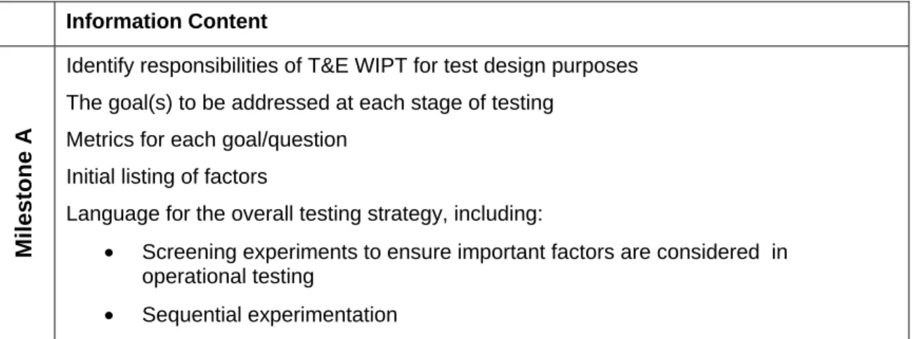
Table 1: DOE Information Content for the TEMP Information Content
Milestone A
Identify responsibilities of T&E WIPT for test design purposes The goal(s) to be addressed at each stage of testing
Metrics for each goal/question Initial listing of factors
Language for the overall testing strategy, including:
• Screening experiments to ensure important factors are considered in operational testing
Design of Experiments – Guidance
3
Milestone B
Identify responsibilities of T&E WIPT for test design purposes The goal(s) to be addressed at each stage of testing
Metrics for each goal/question Refined listing of factors and levels
Test designs to support resourcing for limited user tests (LUT) and operational assessments (OA)
Language for the overall testing strategy, including:
• Screening experiments to ensure important factors are considered in operational testing
• Sequential experimentation
Milestone C
Identify responsibilities of T&E WIPT for test design purposes
The goal(s) to be addressed at each stage of testing, focusing on IOT&E Metrics for each goal/question
Refined listing of factors and levels, based on prior testing and the operational mission. Details on how the factors and levels will be varied and controlled during each stage of testing
Complete test designs to support resourcing for IOT&E Language for the overall testing strategy, including:
• How previous knowledge is being used to inform IOT&E test planning. • Analysis plans to support power calculations
References
Guidance on the use of Design of Experiments (DOE) in Operational Test and Evaluation, DOT&E, October 19, 2010
Montgomery, D. C. (2009), Design and Analysis of Experiments, John Wiley and Sons
Myers, R. H., and Montgomery, D. C. (2002), Response Surface Methodology:
Process and Product Optimization Using Designed Experiments, John Wiley and Sons.
TEMP Body Examples
Precision Guided Weapon Example Appendix Artillery Example Appendix
Design of Experiments – TEMP Body
Example
3.2 Design of Experiments
Design and Analysis of Experiments will be used to develop test plans for the developmental, integrated, and operational testing of system XYZ. The T&E WIPT will identify the following components of the experimental design: (1) goals, (2) metrics, (3) factors and levels that impact the outcome of the test, (4) a strategic method for varying those factors and levels across all tests, and (5) appropriate statistical power and confidence levels for important responses for which they make sense.
The T&E WIPT will use a sequential approach in test planning, meaning that screening of factors will occur in DT and integrated test events, only factors that are deemed significant or of particular operational interest will be investigate in OT. The overarching test strategy outlined in this TEMP is adequate to support the OTA’s evaluation plan. Tables 3.X1 – 3.XX provide the overall DOE strategy for each test objective. The overarching test strategy may change after the initial test events are conducted to allow for increased information on the effect of the factors on the critical responses. See the DOE Appendix for supporting information on the statistical qualities of the experimental design (factor selection, process diagrams, exact designs, and power/confidence levels).
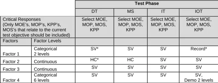
Table 3.X: Overview of DOE Strategy for Test Objective 1 Test Phase
DT MS IT IOT
Critical Responses
(Only MOE’s, MOP’s, KPP’s, MOS’s that relate to the current test objective should be included)
Select MOE, MOP, MOS, KPP Select MOE, MOP, MOS, KPP Select MOE, MOP, MOS, KPP Select MOE, MOP, MOS, KPP Factors Factor Levels
Factor 1 Categorical 2 levels SV* SV SV Record* Factor 2 Continuous HC* HC SV SV Factor 3 Continuous SV SV SV SV Factor 4 Categorical 6 levels SV SV SV SV, Demo 2 levels Note: Table 3.1, Top-Level Evaluation Framework Matrix, should capture the key test goals and metrics/measures that are discussed in the test design section of the TEMP.
Design of Experiments – TEMP Body Example
2
*In Table 3.X there are three common factor management strategies used (1) systematically vary (SV) the factor by including the factor in the experimental design, (2) hold constant (HC) at a fixed level during testing to minimize its impact on the test outcome, (3) record the level of the factor. Additionally, there are two levels of the fourth factor that will only be demonstrated (demo) in operational testing because of the cost associated with testing those levels.
Best Practices for Table 3.X:
Note 3.X can be replicated as many times as needed to ensure that all major test objectives are captured. These tables should not be exhaustive; instead they should capture the major test objectives, the primary measures (or response variables), and the factors that will be considered in test planning.
Recordable factors across all test phases should only be included in the DOE strategy table if they are expected to have a large impact on the outcome of the test objective. Other recordable factors can be included in a footnote and documented in more detail in the test plan.
It is also possible to have a factor or levels of a factor that will be systematically varied during a test but not in a statistically defensible fashion. These conditions are sometimes necessary to demonstrate (demo) in tests for safety, cost, or simply the fact that they rarely occur in regular operation of the system
Design of Experiments – Precision Guided
Weapon Example
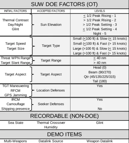
DESIGN OF EXPERIMENTS (for a Precision Guided Weapon) D.1 Design of Experiments (DOE) Definitions
This appendix uses terminology specific to DOE; the following definitions should be applied while reading.
• Initial Factor – A factor determined to potentially impact the performance of the precision guided weapon system in which the weapon system operates. Initial factors are pulled from the test design framework developed by the Operational Test Activity (OTA) or from subject matter expert inputs. Initial factors are accepted on their own, combined with other initial factors and accepted, placed in recordable status, determined to be a demo item, or eliminated from consideration for the DOE design.
• Accepted Factor – a factor accepted as a standalone from an initial factor or through the combination of multiple initial factors. Accepted factors were input into JMP1 software
to create the DOE. Accepted factors are given levels.
• Level – the regions or levels that would be input into JMP software to create the DOE tables. Each accepted factor has a minimum of two levels.
• Recordable (Non-DOE) factor – a factor for which data are recorded during testing, but is not included in the DOE design. Factors that cannot be controlled, but might impact the performance the weapon system are placed into this category. These factors and their values will be recorded and compared against the performance of the weapon system to determine the impact they may have on the system.
• Demo Items – a factor or particular capability that will be tested against but is not incorporated into the DOE design created with JMP software. Demo items will be tested in standalone events if deemed to impact response variable, or incorporated into the DOE events when deemed to not impact response variable.
• Strike Warfare (STW) – the precision guided weapon system when used against Stationary Land Targets (SLT).
• Surface Warfare (SUW) – the precision guided weapon system when used against Moving Maritime Targets (MMT).
D.2.0 Overarching DOE Strategy
The precision guided weapon system effectiveness will depend on its ability to conduct two primary missions:
1 JMP (http://jmp.com/) is the registered trademark for a statistical software package that can assist with experimental design. Design Expert (http://www.statease.com/dx8descr.html), can also be used for DOE.
Design of Experiments – Precision Guided Weapon Example
2
• Surface Warfare (SUW) against MMTs, and
• Strike Warfare (STW) against SLTs
Design of Experiments was used to develop the DT&E, integrated test events, and the IOT&E. A significant amount of data from previous testing of this precision guided weapon system exists, which helped to refine the test design. Captive carry testing will be used to execute the majority of the testing. The captive carry testing uses a precision guided weapon system digital simulation consists of high fidelity guidance and electronics unit (GEU) and seeker models coupled with a target scene generator. The scene generator creates a perspective projection of the infrared target scene as presented to the seeker optics; the scenes are developed from empirical data and incorporate environmental effects such as time of day, sea state, humidity, and atmospheric conditions. Seeker imagery and GEU performance data captured during previous captive carry flight testing has been used to successfully validate the all digital precision guided weapon system simulation. The T&E WIPT consisting of the Technical Program Office, Lead Test Engineers, Systems Engineers, OTA testers, and DOE Subject Matter Experts determined that the appropriate response variables for evaluating the effectiveness of the system are:
• Aim point delta: the distance between seeker aimpoint and the preplanned aimpoint at the final seeker aimpoint refinement. This response variable applies to both the captive carry (CC) and free flight (FF) live fire tests.
• Miss distance: the distance between the preplanned aimpoint and the actual impact point for FF live fire shots.
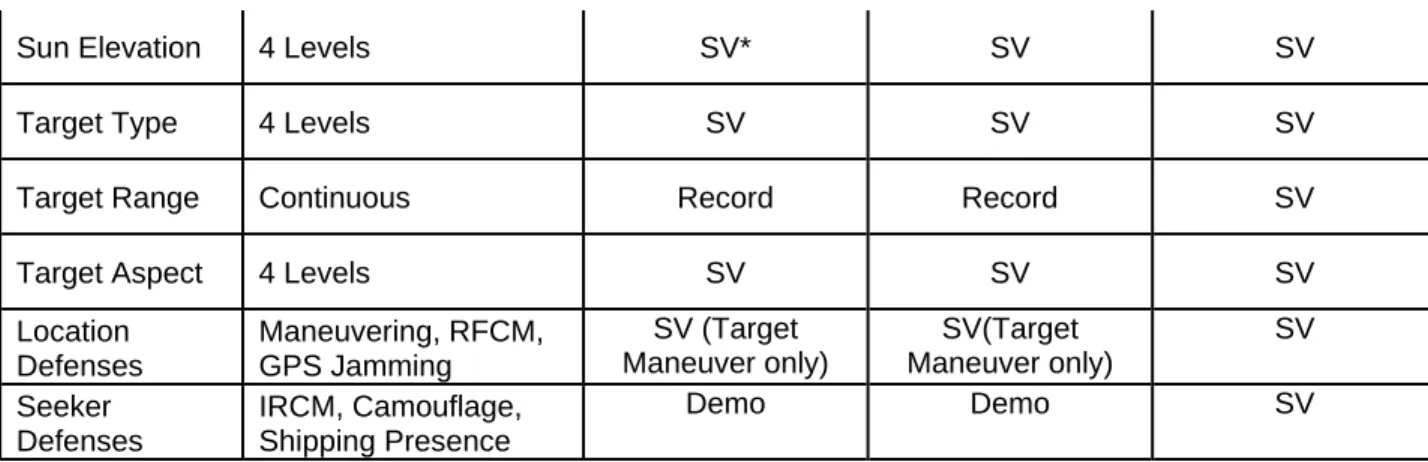
Additionally, the T&E WIPT determined and defined the initial set of factors selected for both SUW and STW missions. These factors were then ranked based on their predicted impact to the response variable and their intended use in the design. Tables D.1 – D.2 provide the overall DOE strategy for each test objective (assessing weapon system effectiveness for SUW Missions and STW Missions).
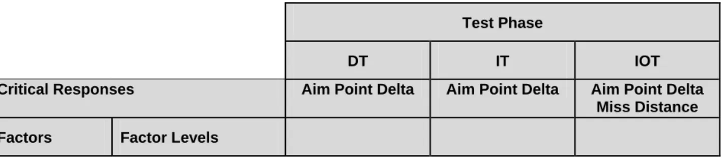
Table D.1: Overview of DOE Strategy for Surface Warfare (SUW) Against Moving Maritime Targets (MMT)
Test Phase
DT IT IOT
Critical Responses Aim Point Delta Aim Point Delta Aim Point Delta Miss Distance Factors Factor Levels
Design of Experiments – Precision Guided Weapon Example
3
Sun Elevation 4 Levels SV* SV SV
Target Type 4 Levels SV SV SV
Target Range Continuous Record Record SV
Target Aspect 4 Levels SV SV SV
Location Defenses Maneuvering, RFCM, GPS Jamming SV (Target Maneuver only) SV(Target Maneuver only) SV Seeker Defenses IRCM, Camouflage, Shipping Presence Demo Demo SV
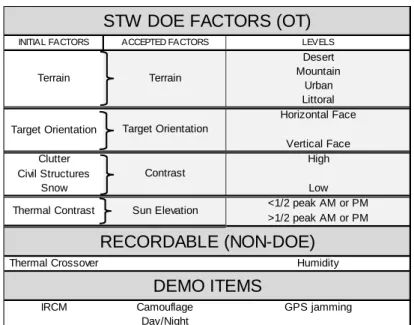
Table D.2: Overview of DOE Strategy for Surface Warfare (STW) Against Stationary Land Targets Test Phase
DT IT IOT
Critical Responses Aim Point Delta Aim Point Delta Aim Point Delta Factors Factor Levels
Terrain 4 Levels
Operational Testing will be used solely to determine system performance
against the less challenging STL
SV Target
Orientation 4 Levels
SV
Contrast Continuous SV
Sun Elevation 4 Levels SV
Defenses
Camouflage, IRCM, GPS Jamming
Demo
D.3.0 Developmental and Integrated Testing
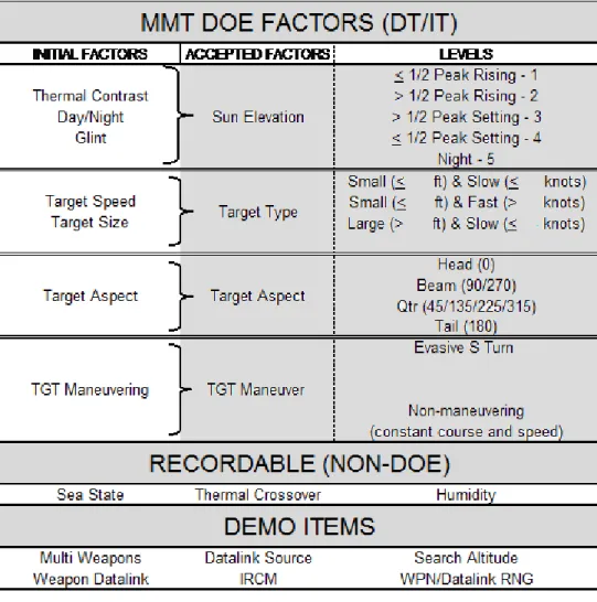
Developmental and integrated testing will focus on the prioritized surface warfare (SUW) scenario against moving maritime targets (MMTs). The factors investigated in DT&E and IT are highlighted in more detail in table D-3 below.
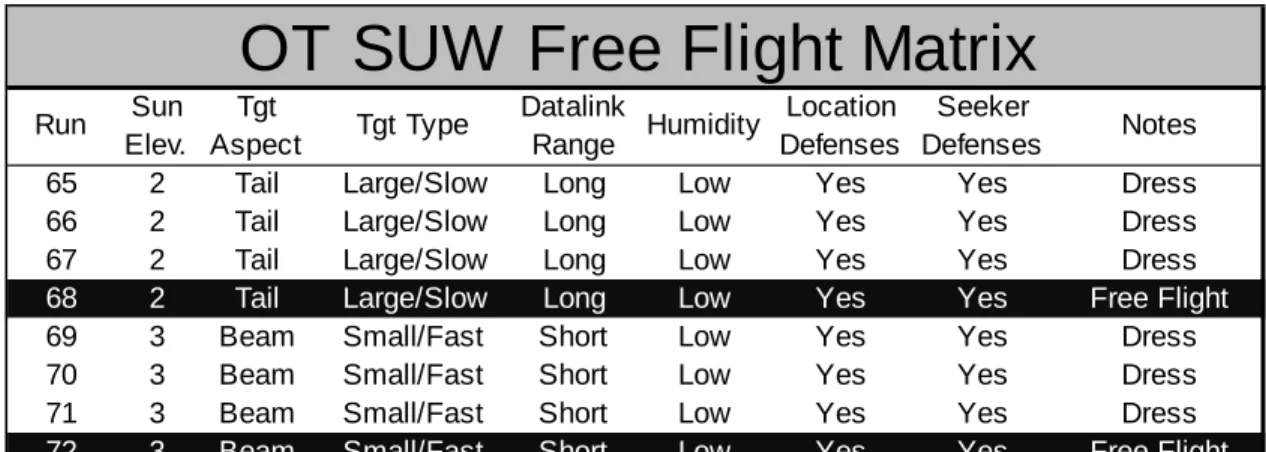
D.3.1 DT/IT Power, Confidence, and Matrix for DOE Runs (MMT)
Using the accepted factors and assuming a normal distribution, the test design was created with JMP software for MMT using a D-optimal design for main effects and two-way interaction estimates. The matrix created includes 60 runs and using 80% confidence and provides sufficient a power to test for main effects. The power for detecting a 2 sigma shift difference in the response for Target Type is 80 percent, for Target Aspect is 63 percent, for Target Manuver is 98 percent, and for Sun Elevation is 51.5 percent. The lower power for Sun Elevation is due to the five levels of the factor and acceptable because it is expected that not all five levels will result in significantly different performance. The data will be collected during 60
Design of Experiments – Precision Guided Weapon Example
4
captive carry runs. In addition to these 60 (30 DT&E, 30 IT&E) data runs, there will be 8 (4 DT&E, 4 IT&E) captive carry dress rehearsals and 4 (2 DT&E, 2 IT&E) free flight live fire runs where the data will be recorded during the MMT DT/IT testing.
Table D-3. MMT DOE for DT&E and IT&E
The overall average miss distance will be compared against threshold values for the system to support the evaluation of the precision guided weapon system CPD requirements. ANOVA and regression analysis will also be performed based on the results. The analysis will provide additional evaluation understanding of overall system capabilities and limitations.
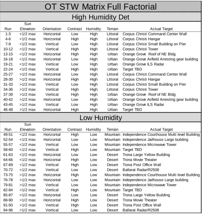
D.4.0 Operational Test DOE Development
In order to better evaluate precision guided weapon system performance in the STW and SUW operational environments, two distinct mission-based DOEs were developed: one for engaging stationary land targets (SLT) and one for engaging MMTs. Since the STW and SUW missions and requirements for precision guided weapon system employment are so different, one combined DOE would not adequately test the system.