SPECIFICATION FOR PIPEWORKS
SPECIFICATION SAJH WS / PW / 001
(Rev.1.0 / 06.2007)
QUALITY ASSURANCE DEPARTMENT SAJ HOLDINGS SDN. BHD.
CONTENTS
PAGE NO.
1.0 GENERAL 1
1.1 Order for Pipes and Specials 1
1.2 Approvals 1
1.3 Hauling and Handling 1
1.4 Records of Pipes Supplied 2
1.5 Prospecting 2
1.6 Pipe Alignment and Cover 3
1.7 Pipelaying in Grounds with High Water Table 4
1.8 Dangers of Flotation 4
1.9 Temporary Cessation of Trench Excavation 4
1.10 Examination of Pipes and Fittings 4
1.11 Laying Pipes and Fittings 5
1.12 Specials 5
1.13 Testing Pipelines 5
1.13.1 General 5
2.0 MILD STEEL PIPES AND SPECIALS
2.1 General 7
2.2 Scope 7
2.3 Definition 7
2.4 Standards and Codes of Practice 7
2.5 Submissions 8
2.6 Pipes and Specials 9
2.7 Steel Pipes 9
2.8 Material, Workmanship and Welding Standards 11
2.9 Pipe Ends 12
2.10 Bends, Tees, Tapers, Etc. 13
2.11 Flanged Joints 13
2.12 Mechanical Couplings, Flange Adaptors and Expansion Joints 14
2.13 Pipes for Closing Lengths 15
2.14 Collars 15
2.15 Retaining Rings 15
2.16 Physical Testing 15
2.17 Works Hydraulic Testing 15
2.18 Ring Girders 16
2.19 Protection 16
2.20 Cleaning and Priming 16
2.21 External Coating 16
2.22 Wrapping 17
2.23 Inspection of External Pipe Coating 17
2.24 Painting Unwrapped Pipes and Specials 17
2.25 Spun Concrete Lining at Factory 17
2.26 Internal Protection at Pipe Ends 19
2.27 Pipework for Laying above Ground 19
2.28 End Protection 20
2.29 Examination of Steel Pipes 20
2.30 Low Friction Coating 20
PAGE NO.
2.31 Handling 20
2.32 Repair of Lining and Sheathing of MS Pipes 21
2.33 Laying MS Pipe 22
2.34 Welding MS Pipe 23
2.35 Making Welded MS Pipe Joints 23
2.36 Air Testing of Welded MS Pipe Joints 24
2.37 Completion of Sheathing at Welded MS Pipe Joints 24 2.38 Completion of Internal Lining at Welded MS Pipe Joints 25
2.39 Testing MS Pipeline 25
2.39.1 Test Pressure 25
2.39.2 Leakage Testing 25
2.40 Protection in Transit 25
2.41 Notice of Deliveries 26
2.42 Pipe Dumps and Storage Yards 26
2.43 Inspection 26
2.44 Marking of Pipes and Specials 27
2.45 Measurement of Steel Pipes and Specials 27
3.0 DUCTILE IRON PIPES AND FITTINGS
3.1 General 28
3.2 Compliance with Standards 28
3.3 Process of Manufacture 28
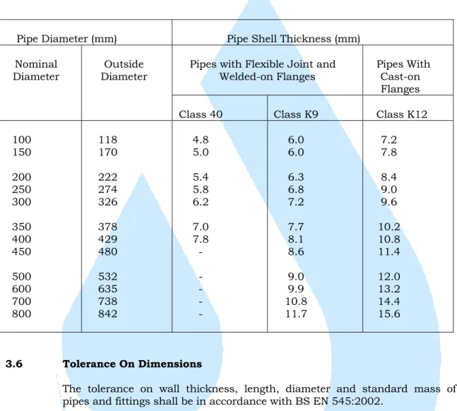
3.4 Thickness and Diameters 28
3.5 Length of Straight Pipes 28
3.6 Tolerance on Dimensions 29
3.7 External Zinc Coating 29
3.7.1 General 29 3.7.2 Zinc Coating 29 3.7.3 Coating Characteristics 30 3.7.4 Verification Process 30 3.7.5 Repairs 30 3.7.6 Finishing Layer 31
3.8 External Coating of Pipes and Fittings 31
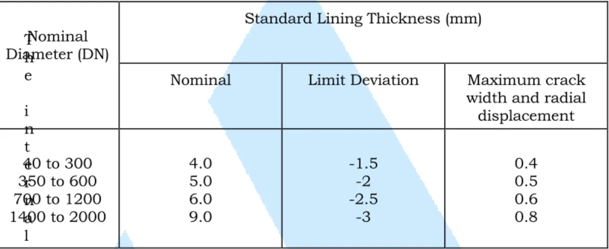
3.9 Internal Lining of Pipes and Fittings 31
3.10 Flexible Joints 32
3.11 Flanged Joints 32
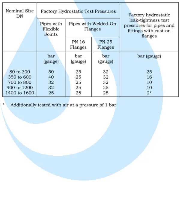
3.12 Factory Hydrostatic Test 33
3.13 Connection to Pipes of Different Type 34
3.14 Cutting of Pipes 34
3.15 Packing 34
3.16 Polyethylene Sheathing 34
3.17 Handling 35
3.18 Laying DI Pipes 35
3.19 Protection Against Damage in Transit 36
3.20 Jointing Ductile Iron Pipe 36
3.21 Testing DI Pipelines 39
PAGE NO. 4.0 POLYETHYLENE (PE) PIPES AND FITTINGS
4.1 General 40 4.2 Scope 40 4.3 Interpretation 40 4.4 Manufacturing Process 41 4.5 Polyethylene Materials 41 4.6 Dimensions 41 4.7 Flanged Connections 42 4.8 Works Tests 43 4.9 Packing 43
4.10 Handling, Transportation and Storage 44
4.10.1 General 44
4.10.2 Handling and Transportation 44
4.10.3 Storage 45
4.10.4 Precautions 45
4.11 Electrofusion Couplers and Tapping Tees 45
4.12 PE Compression Fittings 47
4.13 Examination of Pipes and Fittings 47
4.14 Laying PE Pipes 47
4.15 Welding PE Pipes 48
4.16 Payment for PE Pipe Joints 52
4.17 Testing PE Pipelines 52
4.18 Markings 53
5.0 uPVC PIPES AND FITTINGS
5.1 General 54
5.2 Materials used in Manufacture 54
5.3 Colour 54
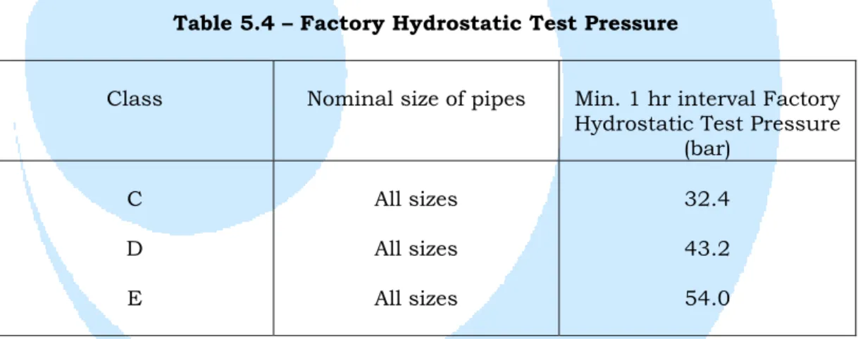
5.4 Classification 55
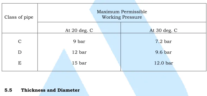
5.5 Thickness and Diameter 55
5.6 Tolerance and Dimensions 55
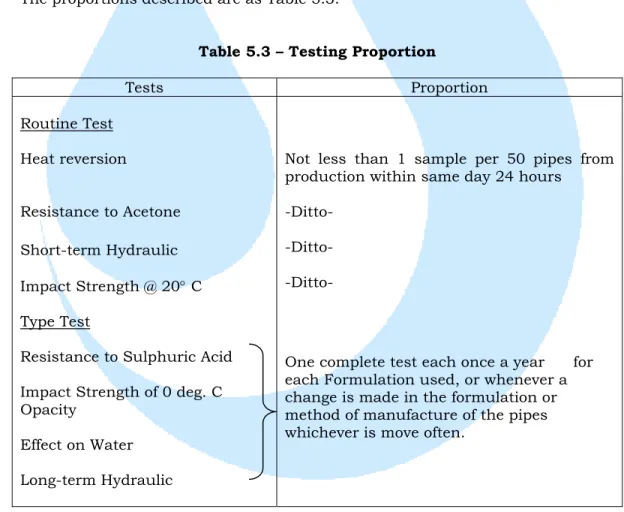
5.7 Length 57 5.8 Appearance 57 5.9 Joints 57 5.10 Pipe Seal 58 5.11 Test Requirements 58 5.11.1 Obligations 58 5.11.2 Routine Tests 58 5.11.3 Type Tests 58 5.11.4 Sampling 59 5.12 Routine Tests 60
5.12.1 Heat Reversion Tests on uPVC Pipes 60
5.12.2 Resistance to Acetone Test on uPVC Pipes 60
5.12.3 Factory Hydrostatic Test on uPVC Pipes 60
5.12.4 Impact Strength Test at 20 degrees C on uPVC Pipes 60
5.13 Compliance 61
5.14 Method of Rejection 61
5.15 Marking of Pipes and Fittings 61
5.16 Test Certificates 62
5.17 Delivery 62
PAGE NO. 6.0 PIPELAYING
6.1 Closing Lengths 63
6.2 Pipe Cutting 63
6.3 Welding Personnel 63
6.4 Making Joints with Mechanical Couplings and Flange Adaptors 64
6.5 Making Flanged Joints 64
6.6 Measurement of DI, Cast Iron, Steel, PE Pipes and Fittings 65
6.7 Concrete Protection to Pipes 65
6.8 Thrust and Anchor Blocks 65
6.9 Valve Chambers 66
6.10 Crossing Over Streams, Culvert and Rivers 66
6.11 Payment for Pressure Testing Pipelines and Specials 66
6.12 Sterilising and Flushing Pipelines 67
6.13 Payment for Sterilising and Flushing Pipelines 67
6.14 Payment for Road Restoration 67
6.15 Clearing Up 68
6.16 Indicator Posts 68
6.17 Painting Pipework and Valves in Chambers 68
6.18 Painting Pipework Above Ground 68
6.19 Disposal of Surplus Goods 69
6.20 Payment of Fees to Authorities 69
7.0 PIPE JACKING
7.1 General 70
7.2 Tender Submission 70
7.3 Surface Reinstatement in Road Verges, Fields, etc. 71
7.4 Prospecting 72
7.5 Performance Requirements 72
7.6 Approval of Owner 72
7.7 Jacking Operation 73
7.8 Safety 74
7.9 Design of the Jacking Pipes 75
7.10 Laying and Connections of Pipeline in Jacked Reinforced
Concrete Pipes Sleeve 76
7.11 Alternative Method of Pipe Jacking 77
8.0 EARTHWORKS
8.1 Definitions 78
8.2 Levels to be Recorded 78
8.3 Explosives and Blasting 78
8.4 Disposal of Materials 79
8.5 Excess Excavation to be Made Good 80
8.6 Site Clearance 80
8.7 Trees 80
PAGE NO. 8.13 Trench Excavation in Roads, Road Shoulders and
Footpaths 82
8.14 Trench Excavation in Fields, etc. 83
8.15 Rock and Other Materials in Excavations 83
8.16 Supporting Excavation 83
8.17 Trimming Excavations 84
8.18 Inspection of Excavation 84
8.19 Filling to Embankments and Backfilling to General Excavation 84
8.20 Trenches Not to be Left Open 85
8.21 Refilling Trench Excavation 85
8.22 Soft Refill Material – Special Measures 87
8.23 Temporary Spoil Tips on the Site 87
8.24 Treatment of Material from Excavation 87
8.25 Surface Reinstatement in Road Verges, Fields, etc. 88
8.26 Works in Roads and Road Reserves 88
8.27 Surface Reinstatement in Roads and Footpaths 89
8.28 Payment for Road Restoration 89
8.29 Other Structures in the Pipeline 90
8.30 Land Drains 90
8.31 Care of Existing Services 91
8.32 Hedges, Fences and Walls 92
8.33 Crossing Watercourses, etc. 92
8.34 Measurement of General Excavation 92
8.35 Measurement of Trench Excavation 93
8.36 Measurement of Filling for Embankment 95
8.37 Payment for Trench Excavation and Restoration 95
8.38 Top Soiling 95
8.39 Turfing 95
8.40 Measurement of Top Soiling and Turfing 96
8.41 Payment for Turfing 96
8.42 Payment of Fees to Authorities 96
9.0 PILING 9.1 General 98 9.1.1 Ground Conditions 98 9.1.2 Setting Out 98 9.1.3 Piling Equipment 99 9.1.4 Programme 99 9.1.5 Pile driving 100
9.1.6 Preliminary and Working Test Piles 101
9.1.7 Load Tests 101
9.1.8 Piling Personnel 101
9.1.9 Piling Records 102
9.2 Precast Reinforced Concrete Piles 102
9.2.1 General 102
9.2.2 Pile Casting 102
9.2.3 Curing, Stripping and Stacking 103
9.2.4 Handling Storage and Transport of Piles 103
9.2.5 Pitching and Driving 103
PAGE NO.
9.2.6 Plant for Pile Driving 104
9.2.7 Measuring Pile Set 104
9.2.8 Extending Piles 105
9.2.9 Preparation of Pile Heads 105
9.2.10 Load Tests 105
9.3 Treated Timber Piles 106
9.3.1 General 106
9.3.2 Treatment of Piles 106
9.3.3 Delivery and Stacking of Piles 106
9.3.4 Pile Driving and Jointing 107
9.3.5 Load Tests 107
9.4 Pile Testing 108
9.4.1 General 108
9.4.2 Test Load and Kentledge 108
9.4.3 Settlement Measurement 108
9.4.4 Equipment and Personnel for Load Test 109
9.4.5 Procedure of Testing 109
9.4.6 Records of Test 110
9.4.7 Interpretation of Test Results 110
9.5 Measurement of Piles and Piling 110
10.0 ROADWORKS
10.1 Preparation of Formation to Receive Road 112
10.2 Earth Subgrade 112 10.3 Subgrade of Rock 112 10.4 Pavement Thickness 113 10.5 Sub-base Materials 113 10.6 Alternative Sub-base 114 10.7 Compaction of Sub-base 114 10.8 Road-base Materials 115
10.9 Laying and Compaction of Roadbase 115
10.10 Finished Surface 117
10.11 Definition and Requirements Associated with Table 10.1 117
10.12 General 118
10.13 Cutback Bitumen 118
10.14 Bitumen Emulsion 118
10.15 Storage, Handling and Heating-of Bitumen 118
10.16 Depot Tray Test 118
10.17 Material 119
10.18 Surface Preparation 119
10.19 Application of Prime Coat 119
10.20 Spraying Procedure 120
10.21 Protection of Prime Coat 120
PAGE NO.
10.27 Laying of Bitumen Macadam 124
10.28 Bituminous Tack Coat 124
10.29 Joints 124
10.30 Laying Around Manhole Covers 125
10.31 Compaction 125
10.32 Road Shoulders 125
10.33 Shoulder Base Selected Fill Grading 126
10.34 Lateral Shoulder Sub-drains 126
10.35 Refilling of Excavated Pipe Trenches for Roadways 126
10.36 Notes Relating to Table 10.1 126
10.37 Geotextile Filter Membrane 128
10.38 Storage of Geotextile Filter Membrane 129
10.39 Laying and Spreading Over the Geotextile Filter Membrane 129
10.40 Laterite Pavement 135
10.40.1 Preparation of Formation to Receive Road
Pavement 135
10.40.2 Pavement Material 135
10.40.3 Spreading and Laying the Laterite Pavement 136
10.40.4 Compaction 136
10.40.5 Rectification of Surface 137
11.0 BRICKLAYER
11.1 Bricks 138
11.2 Cement 138
11.3 Sand for Mortar 138
11.4 Water 139 11.5 Mortar 139 11.6 Mixing Mortar 139 11.7 Brick Laying 139 11.8 Half-Brick Walls 140 11.9 Facing Brickwork 140
11.10 Damp Proof Course 140
11.11 Lintels 140
11.12 Building In 140
11.13 Scaffolding 141
11.14 Valve Chambers and Manholes 141
11.15 Payment for Brickwork 141
12.0 STEEL AND METAL WORKS
12.1 Structural Steel Work 142
12.2 Bolts and Nuts 142
12.3 Steel Chequered Plate 142
12.4 Handrailing 143
12.5 Ladder 143
12.6 Step Irons 143
12.7 Fencing 143
12.8 Aluminium Structures and Sections 144
12.9 Galvanised Metals 144
12.10 Dissimilar Metals 145
PAGE NO.
12.11 Rain Water Pipes 145
12.12 Open Mesh Flooring 145
12.13 Manhole Covers, Surface Boxes, etc. 145
SECTION 1.0 -
GENERAL
QUALITY ASSURANCE DEPARTMENT SAJ HOLDINGS SDN. BHD.
1.0 GENERAL
The Contractor shall supply all the pipes and specials required unless otherwise specified and construct and complete the pipeline and all associated works as specified and included herein under the Contract.
All welding materials, welding equipment, butt and electro fusion equipments, clamps, steel moulds, priming solution, bitumen compound and approved bitumen wrapping tapes or similar material for completing the pipelaying works shall be deemed to be included in the rates of pipelaying unless specific items are provided in the Bill of Quantities.
1.1 Order for Pipes and Specials
The quantities of the items in the Bill of Quantities are only approximate and shall be ascertained by the Contractor after the pipeline profiles are determined by a survey carried out in accordance with Clause 8.2 of earthworks.
Where a pipe special is to be used for connection to existing works, the Contractor shall purchase the special after he has ascertained the existing pipe diameter, flange and other details at the exact location where it is to be laid.
Excess order of pipes and fittings shall be the responsibility of the Contractor and shall be at his own cost.
1.2 Approvals
All pipes/valves/joints/fittings/couplings/adaptors shall undergo for SAJH approval procedure by the QA Department and shall have either ISO Quality Standards Approval, SIRIM/IKRAM or other recognized standard approving authority.
1.3 Hauling and Handling
Great care shall be exercised to ensure that the pipes and specials are not subject to any kind of shock or sudden load during hauling and handling. Attention is drawn to the Contractor that thin wall pipes, defined as pipes with a diameter/plate thickness ratio greater than 125, shall be so handled, stored and transported as to prevent distortion or damage to the pipes and shall not be moved in any manner involving rotation of the pipe about the longitudinal pipe axis. Thin wall pipes during delivery and when in transit around the Site shall be supported on three rubber covered saddles shaped to give at least 90o circumferential support and shall be firmly held in position at each saddles by straps tightened by turnbuckles in such a manner that the external coating is not damaged. One saddle shall be at the
Thin wall pipes in temporary storage or strung out along the pipeline reservoir routes shall be supported on hessian bags filled with fine sawdust straw or similar and shaped so as to give continuous support under at least 40-50 o of the circumference. The positions of supports shall be the same as that for pipes during transit. The underside of the pipes shall be kept clear of the ground by at least 300 mm.
All pipes and pipe specials shall be lifted by means of reinforced canvas slings. The pipes shall be lifted by two reinforced canvas slings at least 300 mm wide suspended from a lifting beam so that the slings are positioned approximately one-fifth of the pipe length from each end of the pipe. On no account shall the pipes and specials be dropped or let fall onto the ground and under no circumstances shall the pipes or pipe specials be lifted by means of hooks to the ends of pipes and pipe specials.
The Contractor shall be deemed to have allowed the cost of providing the above necessary measures in the Contract Rates for hauling and laying. Any damage to or loss of materials shall be made good, or the damaged or lost materials replaced, by the Contractor at his own expense and if approved by the S.O. damaged materials shall be returned to the manufacturer for repair as directed by the S.O.
1.4 Records of Pipes Supplied
The Contractor shall keep full and detailed records including item numbers, size of each, and location of all pipes and specials which are: -
(i) Inspected, taken over and transported to site (ii) Declared to be defective
(iii) Used in the Works
(iv) Cut, broken or removed from Site
The Contractor shall keep such records continuously up to date, and shall have them available for inspection by the S.O. at any reasonable time.
1.5 Prospecting
The Contractor shall prospect for the position of buried or otherwise hidden obstructions such as existing services, drains, pipes, cables, culverts, etc. Trial holes and exploration trenches to ascertain the exact positions of these shall be sunk, well ahead of pipelaying and excavation, in places where they are known or thought to be and elsewhere and these shall be backfilled with approved materials immediately and in any case not exceeding 24 hours and subsequently reinstated. Approved marker posts shall be erected to mark the position of all located services, drains, etc. and these shall not be removed until reinstatements has been completed. The S.O. shall instruct further prospecting if he is not satisfied with the sufficiency of the Contractor's prospecting.
Where necessary the Contractor shall make arrangements prior to trench excavation proper for the temporary or permanent support or diversion of services, drains, etc, to the approval of the S.O. and the authority concerned. The full cost of prospecting shall be deemed to be included in the Contract Rates for pilot excavation.
Attention is drawn to Clauses concerning the responsibility of the Contractor for the security of existing services.
The Contractor shall be deemed to have allowed for the unavoidable delay of the Works due to any obstruction he may encounter with the existing services and no claim for any extra costs on account of this will be allowed.
1.6 Pipe Alignment and Cover
The routes of the pipelines shall be as shown on the Drawings or as directed by the S.O.
Pipes shall be laid to a minimum gradient of 1 on 500 unless otherwise ordered by the S.O. Unless otherwise approved by the S.O. where the gradient of a pipeline is 1 on 20 or steeper, pipes shall be laid on an ascending gradient starting from washout (low point) and finishing at the air valve (high point).
Pipes shall be laid in straight lines on plan but curves of long radius shall be obtained by deflecting MS pipes up to a maximum of 5° for spherical type and 2° for hemispherical type at welded slip joints and using short pipe lengths if necessary. For PE pipes the limitation for deflection does not apply.
Allowable angles of deflection for D.I. pipes are as follows: - Nominal Diameter (mm) Allowable angle of deflection
80 - 200 5º
250 - 300 4º
Generally, for pipework of diameter below 1000 mm, the minimum cover to the top of pipes shall be 1000 mm and at road crossings the minimum cover shall be 1500 mm unless otherwise specified. For pipework of diameter 1000 mm and above, the minimum cover to the top of pipes shall be 1500 mm unless otherwise shown on the Drawing.
Before commencing excavation the route of the pipeline shall be pegged accurately. Strong sight rails shall be fixed and maintained at each change of direction and gradient, and at as many intermediate points not more than 35 metre apart as may be necessary. On these rails shall be marked the centre line and the level to which the pipe is to be laid.
1.7 Pipelaying in Grounds with High Water Table
The Contractor shall note that some parts of the pipelines will be laid in grounds with high water table, especially in areas adjacent to the streams river crossings and ponds in the vicinity.
All costs for dewatering and keeping all the excavations and trenches dry for the whole pipelaying work and in a safe manner during construction shall be deemed to be included in the Contract Rates except where specific provision is made in the Bill of Quantities.
1.8 Dangers of Flotation
Although flotation of pipes in completely refilled trenches or of the completed works will not occur, the Contractor's attention is particularly drawn to the danger of flotation of pipes laid in trenches left unrefilled and allowed to be flooded with water in the partially completed works.
The Contractor shall, immediately after pipes have been laid, jointed and approved by the S.O., refill and compact excavated material to at least two thirds of the length of the pipe trench leaving only sufficient space unrefilled to allow for the completion of the external joint or fittings. Notwithstanding this, the Contractor shall make all necessary provision to avoid the flotation of any pipe during the construction stage.
Any damage caused by flotation of pipes, specials or fittings in unrefilled trenches shall be made good to the satisfaction of the S.O. at the Contractor's own expense.
1.9 Temporary Cessation of Trench Excavation If in the opinion of the S.O. there is undue delay in :- (i) Refilling pipe trenches
(ii) Jointing of PE pipes above ground to form string ready for laying. (iii) Laying and testing the pipelines
(iv) Removing surplus material
(v) General tidying up of areas where pipes have been laid (vi) Partial restoration or maintenance of surface
the S.O. may order that no further trench excavation shall be opened until the outstanding work has been carried out to his satisfaction and the Contractor shall have no ground for a claim against the Employer on this account.
1.10 Examination of Pipes and Fittings
All pipes and specials shall be thoroughly cleaned and carefully examined for cracks and flaws both internally and externally immediately prior to laying. Materials found to be damaged in any way shall be shown to the S.O. who will give instructions regarding remedial work or otherwise.
1.11 Laying Pipes and Fittings
All pipes and fittings shall be laid to the lines and levels shown on the Drawings or as otherwise directed by the S.O.
1.12 Specials
The approximate positions of all specials are shown on the Drawings. The exact positions shall be determined on Site by the Contractor to the approval of the S.O.
1.13 Testing Pipelines 1.13.1 General
After a length of the pipeline has been completed it shall be tested as a whole against stop ends. The stop ends shall be supplied and fixed by the Contractor and shall be properly strutted to ensure that no movement can take place and they shall be of sufficient strength to withstand the full test pressure which is to be applied.
Testing shall be carried out over lengths of approximately (2) two kilometre where possible or the full replacement length between washout or overcrossings but not against adjacent valves. Testing shall not be carried out until the backfilling of the pipe trenches except at the joints, have been completed. Backfilling at flexible joints shall be left uncompleted to facilitate inspection of these joints during testing.
Temporary marker posts shall be installed immediately after testing at all junctions between tested lengths.
Before any length of pipeline is subjected to test pressure, care shall be taken to ensure that all weight, thrust and anchor blocks intended to prevent vertical and lateral displacement of pipes or specials have been properly completed. All valves shall be checked before the test to ensure that they are in working order.
Prior to filling the line with clean water for water testing, the line shall be thoroughly inspected jointly with the S.O. to ensure that the line is cleaned from stones, dirt, debris, plastic paper or any other matter that may have entered after laying of pipework.
The water for filling and testing the pipeline shall be obtained from an approved source. It shall be free from silt, contamination and pollution. The Contractor shall make all arrangements necessary for conveying the water to the point of filling. The test ends shall be tapped for suitable size test connection. When using high pressure pumps for water feeding, regulate the feed slowly to allow minimum or bubbles into the pipeline.
The Contractor shall supply all necessary apparatus including pipework, pumps, flowmeters and pressure charts/recorders and carry out all work necessary to test the pipeline. Pressure gauges are to have a dial at least 200 mm in diameter and shall have unit graduations on the gauges of not more than 0.1 bar. The pressure recorders shall have the ability to record pressures down to 0.1 bar. The gauges and recorders are to be checked against a guaranteed standard unit before use and at other times as the S.O. may direct. The flowmeter to measure the quantity of flow pumped shall be suitable for the flowrate of the pumps supplied by the Contractor. The flowmeter shall have an accuracy of not more than 2% at transition flowrate of the meter as specified in BS5728. The flowmeter shall have an integral totaliser display built-in.
The S.O. will attend all tests and all apparatus and methods shall be to his approval. No length of pipeline shall be deemed to have passed its pressure test until the S.O. has issued a certificate to the Contractor to this effect.
Substantial completion will not be certified before the mains have been successfully water tested.
The Contractor shall take all necessary steps to locate any leakage, supply necessary materials and make necessary repairs or remake any joints, and restore the ground at no extra cost to the Contract until, on retest, the requirements of permissible loss are complied with.
A pressure test on washout pipework shall not be required. The performance of washout pipework shall, however, be observed during flushing of the pipelines after testing. Each scour valve in turn shall be opened fully under the normal working head in the pipeline for sufficient time to allow proper flushing of the pipeline and to check the watertightness of the washout pipework. All water used for testing purposes shall be recorded. The Contractor shall carry out any necessary remedial work to pipework as directed by the S.O.
SECTION 2.0 –
MILD STEEL PIPES AND
SPECIALS
2.0 MILD STEEL PIPES AND SPECIALS 2.1 General
All pipes, specials and fittings must be from SAJH approved sources and be to SAJH specifications (SAJH PS/MS/001).
2.2 Scope
This section of the Specification covers the requirements for the manufacture and testing of welded steel pipes together with specials complete with internal and external protection systems.
2.3 Definition
The following terms shall have the meanings hereby assigned to them except where the context clearly renders these meanings inapplicable.
"Pipes" means straight pipes, whether whole or in cut lengths.
"Pipe specials or specials" means tees, bends, tapers, collars, flange adapters, blank flanges, expansion joints, mechanical joints, ring girders and similar accessories.
2.4 Standards and Codes of Practice
The following Standards and Codes of Practice are referred to in this section of the Specification. The Standards or Codes shall be the latest edition current at the time of its preparation unless otherwise specified for particular application:-
API 5L : Line pipe
API 5LS : Spiral-weld line pipe
API 1104 : Standard for welding pipe lines and related facilities
BS Handbook 19 : Methods for sampling and analyses of iron, steel and other ferrous metals
BS 12 : Specification for ordinary and rapid hardening
Portland cement
BS 3601 : Specification for carbon steel pipes and tubes with specified room temperature properties for pressure purposes
BS 729 : Hot dip galvanised coatings on iron and steel
articles
BS 534 : Steel pipes, fittings and specials for water, gas and sewage
BS 903 : Methods of testing vulcanised rubber
BS 1154 : Specification for natural rubber compounds
(high quality)
BS 2494 : Materials for elastomeric joint rings for pipework and pipeline
BS 2569 : Sprayed metal coatings
BS 4147 : Hot applied bitumen based coatings for ferrous products
BS 4232 : Surface finish of blast-cleaned steel for painting BS 4360:1986 : Weldable structural steels
BS 4504 : Flanges and bolting for pipes, valves and fittings Part I: Ferrous
BS 4515 : Welding of steel pipelines on land and offshore.
BS 5135 : Process of arc welding of carbon and carbon
manganese steels.
BS 5292 : Jointing materials and compounds
BS 5500 : Unfired fusion welded pressure vessels AWWA Mll : Steel pipe design and installation
2.5 Submissions
The Contractor shall provide drawings, calculations and data in respect of the following:-
i) For pipes and specials :
Drawings with descriptions to show the method of forming pipes and fittings in standard lengths from steel sheets or strip.
ii) For joints :
Drawings for spigot and socket joints showing allowable tolerances and arrangements to permit air testing of completed joints on Site.
iv) For internal lining:
Full details of method of lining and curing including details and sieve analyses of materials to be used and type of cement.
v) For external coating:
Full details of coating process to be used, including details of the bitumen and the inner and outer wrappings or equivalent subject to the approval of the S.O.
2.6 Pipes and Specials
All pipes and specials shall be provided by the Contractor and delivered to the Site. Each item supplied shall be suitably marked to permit identification with items in the Bill of Quantities.
2.7 Steel Pipes
Steel pipes shall be manufactured, except where stated otherwise hereunder, in accordance with BS 534. Material for pipes shall be made from carbon steel plate to Grade 43A of BS 4360:1986 or better with a minimum lower yield stress of 275 N/mm2 supplied in plate or strip form as of appropriate for the method of pipe manufacture. The pipes shall be formed by the automatic submerged arc process, with either a longitudinal seam or a spiral seam at the option of the Contractor. With the method of manufacture decided upon, the relevant standard will then apply i.e. BS 534
The Contractor shall provide a ladle analysis of the steel used for the pipes in accordance with Clause 7.1 of BS 4360:1986. Check analyses of the finished pipe shall be taken in accordance with Clause 7.2 of BS 4360:1986. In case of dispute, the methods of chemical analysis shall be in accordance with BS Handbook No. 19.
Unless otherwise specified, thickness of the steel pipe shells and the finished internal diameters of the pipes shall be as shown in the following table :- Outside Diameter (O.D) (mm) Nominal Diameter (ND) (mm) Minimum Nominal Thickness (mm) Concrete Lining Thickness (mm) Bitumen Enamel Wrapping (mm) Mass per length (plain end) Hydraulic Test Pressure (Steel430) 88.9 114.3 139.7 168.3 193.7 219.1 244.5 273 323.9 355.6 406.4 457 508 559 610 660 711 762 813 864 914 1016 1219 1422 1626 1829 2032 2235 80.0 100 125 150 175 200 225 250 300 350 400 450 500 550 600 650 700 750 800 850 900 1000 1200 1400 1600 1800 2000 2200 3.2 3.6 3.6 3.6 4.0 4.0 4.0 4.0 4.0 4.5 4.5 5.0 5.0 6.3 6.3 6.3 6.3 6.3 7.1 7.1 7.1 7.1 8.0 8.8 10.0 11.0 12.5 14.2 6 6 6 6 10 10 10 10 10 13 13 13 13 13 13 19 19 19 19 19 19 19 19 25 25 25 25 25 3 3 3 3 4.5 4.5 4.5 4.5 4.5 6 6 6 6 6 6 6 6 6 6 6 6 6 6 6 6 6 6 6 6.76 9.83 12.1 14.6 18.7 21.2 23.7 26.5 31.6 39.0 44.6 55.7 62.0 85.9 93.9 102 109 117 141 150 159 177 239 307 399 493 623 778 70 70 70 70 70 70 70 64 54 56 49 48 43 50 45 42 39 36 38 36 34 31 29 27 27 26 27 28 * The above finished minimum steel shell thickness shall not be subject
to any negative tolerance for acceptance purpose.
The thickness of pipes used for branch pipework off the main pipelines or for use in forming specials shall be the greatest of the following:-
(a) The thickness necessary to provide the same outside diameter to wall thickness ratio specified for straight pipes.
(b) The thickness determined to be necessary in the design of specials as shown on the Drawings.
Unless otherwise approved by the S.O., standard length straight pipes shall be manufactured with not more than three circumferential joints and with an effective length as shown in the table below:-
Finished Internal Diameter (mm) Standard Length (m) 450 and above Below 450 9 6 As per SAJH PS/MS/001
The allowable tolerance on standard length pipes shall be + 150 mm. In addition a number of straight pipes of half the standard length pipes and truly circular standard straight pipes shall be supplied. All standard and half length pipes shall have ends formed as specified below for joints capable of angular rotation. Truly circular standard straight pipes required for cutting purposes shall be truly circular throughout the length.
All pipes whether manufactured with a longitudinal or spiral seam shall be subjected to non-destructive testing of seam welds and skelp.
2.8 Material, Workmanship and Welding Standards
Material inspection before rolling shall be carried out to check against Mill Certificates submitted for conformity with the BS 4360. This shall include determination of country of origin, manufacturer, physical inspection, checking of thickness and visual inspection of edges for lamination.
As a control on weld quality the Contractor shall be required to take and submit radiographs for 3% of all welded length. The acceptance of these radiographs shall be in accordance with BS 534 or equivalent as directed by the S.O.
Weld defects shall include cracks, lack of complete penetration, lack of complete fusion, and undercutting or reduction in pipe wall thickness adjacent to a weld exceeding 0.5 mm in depth.
Slag inclusions and gas pockets or voids considered to be minor imperfections may be accepted if the maximum size and distributions does not exceed the limits.
Where radiographic examination reveals defects in the welds the S.O. will either reject the length of pipe containing such defects or will permit the Contractor to carry out repairs and to submit radiographs of such repairs for clearance. Lengths of pipe containing defects in welds after repair will be liable to be rejected.
If defects in welds are found in a length of pipe or specials, the welds of the pipes and specials immediately before and after the defective pipe or specials in the production line shall be radiographed until the S.O. is satisfied that all the welds are considered satisfactory. The cost of such radiographs of repaired welds shall be included in the Contract Rates and shall not form part of the 3% of all welded length specified in the first paragraph of this Clause.
2.9 Pipe Ends
Ends of pipes to be jointed shall generally be as follows :-
(a) Spigots and sockets for jointing in trench or above ground.
(b) Plain ends for use with welded collars, mechanical couplings or flange adaptors.
The spigot and socket joints for the spherical type shall be designed to take angular deflections of up to 5 degrees from the axial to accommodate changes of pipe gradient and/or direction at individual joints. For hemispherical type, the angular deflections shall be up to 2 degrees.
Spigot and socket joints shall be of the spherical or hemispherical sleeve type with a minimum penetration of the formed ends. The joint design shall provide for the contact surface of the spigot end and the sleeve end to be formed to the same spherical radius which shall be more than 50% of the outside diameter of the barrel of the pipe for the spherical type and shall not be less than 50% of the outside diameter of the barrel of the pipe for the hemispherical type. The minimum penetration of the spigot into the socket shall not be less than four times the pipe thickness and this overlap shall be obtained at the maximum deflection of 5 or 2 degrees excluding pipe lining. At zero deflection the minimum overlap shall be the minimum penetration as above increased by such allowance as is necessary to ensure contact between the spigot and socket over the specified maximum amount of joint movement. The joint engagement tolerance in any position shall not exceed an average of 1.60 mm with maximum isolated gaps of 2.00 mm adjacent to the weld seams.
Pipe ends of the spherical or hemispherical type shall be formed by hydraulic pressing using a full circle die or expanding former capable of forming ends consistently to a constant spherical contact surface throughout the pipe production run.
The internal surface of the socket and the external surface of the spigot shall be ground smooth along the shop fusion welds for a distance of 150 mm from pipe ends measured along the pipe axis.
The external surface of the plain ended pipes shall be similarly prepared. All sockets shall have two tapped holes spaced at 90 degrees apart on the circumference. They shall be of not less than 6 mm diameter and shall be provided with matching plugs to facilitate the air pressure testing of field welds. These tapped holes shall be located within the end 30 mm of the sockets and shall be cleared of welding runs.
Ends prepared for butt welding shall be subject to manufacturing tolerances in accordance with Table 6.3 of Std 5L or Table 6.2 of Std 5LS.
Plain ends for use with mechanical joints or flange adaptor joints shall be truly circular with a diameter tolerance of + 1 mm over a distance of 225 mm from the pipe ends.
2.10 Bends, Tees, Tapers, Etc.
Special items such as bends, tapers, tees, etc, shall be formed from completely lined pipes as specified by suitable insertion of rubber spacers during lining operation. The coating and lining on the straight pipes shall be cut back from the ends to be welded or cut for a sufficient distance to ensure that no material which is intended to remain part of the coating/lining is damaged or affected by the welding or cutting process.
Pipe specials shall be designed to withstand the full specified factory test pressures. Compensation plates and gusset plates shall be in accordance with BS 5500.
Welding shall be of a standard equal to that of straight pipes and each butt weld shall be subjected to a 100% radiographs test. Fillet welds shall be subjected to air tests where appropriate and/or magnetic particle testing. The outside diameter of specials shall conform to the outside diameters of the standard straight pipes. The ends of plain ended specials shall be truly circular and shall conform to the tolerances required for the fitting of mechanical couplings and flange adaptors.
2.11 Flanged Joints
All flanges shall be of steel, welded to the pipe by the electric arc process or other approved method. They shall conform in all respects with the requirements of BS 4504 unless otherwise specified. They shall be of the raised face type and shall be truly faced over their whole width. Bolt holes shall be drilled off centre lines, truly in line end to end with the longitudinal axis. All flanges shall be rated as 16 bar and confirm to table 11 of BS 4504 unless otherwise stated. All flanges shall be adequate to withstand test pressures for the fittings to which they are attached and shall be in accordance with BS 4504.
All materials required for use in the making of flanged joints including nuts, bolts, washers and joint gaskets shall be supplied by the Contractor. Joint gaskets shall be contained within the bolt pitch circle and shall be made from 4.5 mm thick rubber to BS 1154 Class Y3 reinforced with two layers of fabric in accordance with BS 5292. Each bolt shall be supplied and installed with a nut and two washers and each bolt shall be of sufficient length to show two threads past the nut when so installed.
Test certificates for the flange material shall be supplied. The finish on flange joint surfaces shall be in accordance with Clause 4.4 of BS 4504.
Blank flanges shall be designed and supplied by the Contractor for an end loading equivalent to the rating pressure of the flange. Lifting eyes or handles and air release cocks shall be provided as necessary.
Thrust flanges shall be designed to withstand a longitudinal force equal to the loading applied to a blank flange of equivalent diameter.
2.12 Mechanical Couplings, Flange Adaptors and Expansion Joints
Mechanical couplings for jointing plain ended pipes shall be of an approved make capable of maintaining a watertight joint over a range of axial movement between the pipe ends of at least 9.5 mm and with up to 3 degrees angular deflection between the longitudinal axis of the pipes.
Flange adaptors for jointing plain ended pipes to fittings shall be of an approved make capable of maintaining a watertight joint over a range of axial movement of at least 4.8 mm and an angular deflection of not less than one and a half degrees. All flanges shall be drilled in accordance with BS 4504 and details derived from flange design computation based on 16 bar pressure rating by the Contractor.
Expansion joints shall be provided to conform with details as shown on the drawing. They shall be supplied complete with all accessories.
All necessary couplers, joint rings, nuts, bolts and washers, etc. required for completing joints shall be supplied by the Contractor. All bolts, nut and washer shall be hot-dip galvanised in accordance with BS 729.
Couplings shall be supplied with or without a central register or locating plugs as required. The central collar shall be at least 1.5 mm thicker than the equivalent standard pipe thickness.
Every coupling, flange adaptor and expansion joint shall be capable of withstanding without leakage the pressure required for the works hydraulic test of the section of pipeline in which it will be incorporated. The pressure rating shall be clearly stamped on all couplings and adaptors. The rubber joint rings shall be Type 1 to BS 2494 having a hardness range of 45-65 degrees measured in accordance with BS 903 and tensile stress-strain properties detailed in Table 3 corresponding to the relevant hardness.
All metallic parts are to be descaled to first quality standard in BS 4232 and protected with two coats of approved two-pack epoxy based enamel unless otherwise stated. The enamel shall be taint free, non-toxic and chlorine resistant.
All welding protrusion shall be machined finished. Mechanical couplings and flange adaptors shall be hydraulic tested at the place of manufacture one in every five for each size of coupling and adaptor. Test certificate shall be provided by manufacturer.
Every expansion joint shall be hydraulic tested at the place of manufacture prior to delivery.
2.13 Pipes for Closing Lengths
Pipes to be used for closing lengths shall be correctly sized over their full length so that accurate alignment for split collar joints can be obtained. All such pipes shall be clearly marked.
2.14 Collars
Collars shall be provided for jointing cut pipes or closure pieces by means of internal and external fillet welding. Minimum lengths of collars shall be 250 mm. Collars may be provided as single split collars with temporary bolts and lugs. Collars shall have two tapped and plugged holes of not less than 6 mm diameter to permit air pressure testing of the joints after field welding, one each side of the collar clear of the welding runs and approximately 25 mm from the edge of the collar. The collar shall be 1.5 mm thicker than the equivalent standard straight pipe thickness. Collars shall make close contact around the circumferences of both pipes connected and the gap between the ends of a split collar after tightening shall not exceed 3 mm. Split collar ends shall be prepared for butt welding in the same manner as plain ends of pipes prepared for butt welding in accordance with Std 5LS. The tolerances of the collar shall be such that nowhere shall the gap between the inside surface of the collar and the outside surface of the pipe at fillet weld locations exceed the tolerances permitted for spigot and socket joints.
The overlap on each pipe shall not be less than 75 mm. Collar joints shall not be required to take any deflection.
2.15 Retaining Rings
All flanged pipe ends, flanged branches and plain ends for use with mechanical couplings or flange adaptors shall have a 6 mm steel retaining ring welded into the bore of the pipe flush with the end of the pipe after which the ring shall be zinc phosphate coated as specified followed by two coats of bituminous paint. The radial thickness of the rings shall be similar to the thickness of the concrete lining and shall not be less than 6 mm. The ring shall be protected with two coats of approved two-pack epoxy based enamel if it is too thick to be effectively covered by the concrete lining.
2.16 Physical Testing
Unless otherwise specified physical testing of the pipes shall also be in accordance with Section 4 of Std 5L/S.
2.17 Works Hydraulic Testing
All pipes shall be hydraulically tested at the place of manufacture in accordance with BS 3601. Full test pressures shall be maintained for at least 3 minutes during testing at the factory and automatic pressure recorders must be installed on hydraulic testing machines.
Any pipe which fails to withstand the hydraulic test pressure or which exhibits signs of porosity shall be deemed not to comply with this Specification and shall be rejected unless otherwise decided.
2.18 Ring Girders
Ring girders shall be provided to conform with details shown on the Drawings. They shall be supplied complete with all accessories. Metallic parts are to be descaled to first quality standard in BS 7079 and painted with two pack polyamide cured epoxy zinc phosphate primer with 75 microns minimum dry film thickness.
2.19 Protection
All pipes shall be protected both internally and externally against corrosion. The pipes shall be protected externally with a double reinforced bitumen enamel wrapping followed by internal protection with spun concrete lining. Both types of protection shall be applied under factory conditions but not necessarily at the place of manufacture of the pipes.
Internal and external protection at joints shall be completed on Site after acceptance of joint weld tests.
2.20 Cleaning and Priming
Where bitumen wrapping is to be applied at the place of pipe manufacture, cleaning and priming shall immediately follow hydraulic testing. Where bitumen wrapping is to be applied at another location, then the pipes shall be coated with a suitable corrosion inhibitor before despatch from their place of manufacture.
Immediately prior to priming, all pipes shall be thoroughly descaled by shot blasting internally and externally to BS 4232 second quality.
If the spun concrete lining is to be applied at the place of pipe manufacture, internal priming of the pipe barrel may be omitted. Otherwise pipes shall be primed both internally and externally.
The above priming shall stop short of the ends of pipes intended for field welding. The ends of such pipes shall be coated with an approved priming paint and/or rust inhibitor both internally and externally. This shall be suitable for providing a temporary protection from rusting prior to field welding those areas of pipe not given the full factory applied permanent protection and shall not affect the weldability of the metal.
and there shall be not less than 2 mm of bitumen between the inner and outer wraps, and between the pipe and the inner wrap.
The coating shall be stopped short as shown on the Drawing for ends of all spigot and socket pipes, and 250 mm from the ends of all plain ended pipes for use with mechanical couplings or flange adaptors. The edge of the wrapping shall be chamfered at 25 degrees.
2.22 Wrapping
The wrapping materials shall be spirally wound onto the pipes and specials simultaneously with the bitumen coating. Each wrap shall be from 150-225 mm wide and the edges shall overlap by 12-25 mm. Care shall be taken to ensure that the inner wrap does not come into contact with the pipe metal or with the outer wrap.
The inner wrap shall be a glass fibre resin-bonded tissue reinforced in the longitudinal direction with parallel glass threads spaced 10 mm apart. The nominal thickness shall be 0.5 mm and the minimum weight shall 0.046 kg/m2.
The outer wrap shall be of glass fibre resin-bonded tissue reinforced in the longitudinal direction with parallel glass threads spaced 10- 25 mm apart. It shall be impregnated with a material fully compatible with the bitumen coating to give a finished thickness of 0.75 mm.
2.23 Inspection of External Pipe Coating
All coated pipes and specials shall be rigidly inspected for defects. Thickness shall be determined by a pit gauge, continuity with a holiday detector and coating quality by cutting out 75 mm square samples at the rate of one sample per 5 lengths of pipe manufactured.
The whole coated surface area of all pipes and specials shall be tested for pinholes or other invisible defects in the coating using an approved holiday detector at a potential of 14,000 volts.
Any lengths on which the coating is, in the opinion of the S.O. poorly applied shall be cleaned to bare metal and re-coated. Minor defects may be repaired by touching up. All repairs shall be checked for thickness and continuity. 2.24 Painting Unwrapped Pipes and Specials
All unwrapped pipes and specials shall be given two layers of primer coat of Red Lead Oxide and two layer of final coat of light green zinc chromate. The internal lining will be similar to the requirement of wrapped pipes. 2.25 Spun Concrete Lining at Factory
All pipes and specials shall be lined with concrete. Cement for lining shall be ordinary Portland cement to BS 12. Aggregate shall be well-graded clean fine
aggregate and the maximum particle size shall not exceed 8 mm or one third the thickness of the lining, whichever is the lesser. All materials used in concrete for lining shall comply with the requirements for concrete.
The final aggregate grading and concrete mix proportions shall be such that a hard, durable and dense concrete lining is obtained that satisfies the tests laid down in Clause 33 of BS 534. Unless otherwise approved, the minimum cement content shall be 330 kg/m3 and the water cement ratio of the mix loaded into the pipe shall not exceed 0.42. Tests shall be carried out during the lining of pipes to demonstrate that the concrete lining has a strength equal to or greater than the minimum figures stated in Clause 33.5 of BS 534. The frequency of these tests shall be at least once every 250 m length of pipe lined or during each working shift, whichever is the greater.
The testing of concrete cubes shall be conducted at the factory of manufacture and certificate for testing shall be provided.
All straight pipes shall be concrete lined by the use of a lining machine designed and built for the purpose of rotating the pipe and centrifugally applying the lining at sufficient speeds to meet the requirements set out below. The support or holding device for the pipe shall be such as to avoid damage to the pipe coating during the spinning operation. If the pipe is rotated by direct contact drive from the machine it shall be supported over at least 90 degrees of its circumference and driven by non-metallic surfaced belts of sufficient width to avoid coating damage. The speed of rotation of the pipe during the lining compaction stage shall be such as to provide a radial acceleration of at least 250 m/s2. The rotational drive shall be capable of close control and provide smooth acceleration and deceleration when working up to and down from the compaction spinning stage.
Immediately before lining commences, the pipe bore shall be cleaned of all loose scale, rust, oil, grease or any other foreign matter likely to contaminate or harm the concrete. Areas where an approved priming coat has bonded to the pipe such that wire brushing does not cause areas to flake off will be acceptable as a base for applying the lining.
The entire quantity of concrete required for the lining shall be applied without interruption, and spinning shall continue until the specified thickness is evenly distributed over the inside of the pipe, all surplus water has been removed and the greatest possible density of concrete has been obtained. Tolerance on the thickness of lining shall be as follows :-
(i) +3 mm to -2 mm for 25mm and above (ii) +2 mm to -1 mm for 19 mm and below
Temporary or semi-permanent end restraints shall be fixed to the pipe ends on completion of lining and before removal of the pipe from the lining machine. The pipe shall not be rotated about its longitudinal axis after the fixing of the restraints when being handled and transported to the storage yard and subsequently to the Site.
accordance with Clause 33.2 of BS 534. During the lining process, all rebound material, dribbles, etc. shall be removed so that the lining is applied in a homogeneous mass to a clean surface.
Inspection of the lining shall be carried out at any time prior to and after installation of the pipes. Any pipe with lining that is broken, defective or otherwise not in accordance with the Specification may be rejected. Remedial lining operations may be carried out by a method that has been approved in writing in advance by the S.O.. The standard of the remedial lining shall satisfy the requirements of this Specification.
Surface crazing of the lining will be acceptable unless cracks are severe enough that they can be penetrated to a depth of 2 mm by a 250 microns feeler gauge at 10 points or more over a length of 300 mm when measured with the lining in a saturated condition. These cracks shall be cut back to full depth and sealed with an approval epoxy resin filler.
Linings applied to pipes shall be cured in such a manner as will enable concrete to obtain and subsequently retain optimum strength, density and durability.
Linings shall be kept moist by continuous water spraying for a period of at least 3 days. They shall then be protected from sunlight and kept damp by spraying with water or other means approved by the S.O. for a further period of 7 days. Pipes shall not be removed from the factory until at least 14 days have elapsed from the date of lining.
2.26 Internal Protection at Pipe Ends
Concrete shall be omitted at the following locations :- a) Spigot & Socket Ends
The lining shall terminate as shown on the Drawing. The edge of the lining shall be angled back at 3mm to the pipe axis in order to provide a positive key for in-situ joint protection.
b) Plain Ends
For butt straps or collar joints, the lining shall terminate 90mm back from the pipe end. The edge of the lining shall be angled back at 3mm.
For mechanical coupling and flange adaptor joints, the lining shall be brought right against the retaining rings.
2.27 Pipework for Laying above Ground
Uncoated steel pipes and specials required for installation above ground shall be cleaned to BS 4232 second quality and protected with two layers of primer coat of Red Lead Oxide and two layer of final coat of approved zinc chromate primer.
2.28 End Protection
The concrete lining and the external coating of pipes and specials to be jointed by welding shall be omitted for a sufficient distance from the ends to prevent damage to the protection during site welding.
The unlined surfaces shall be protected with a suitably approved ensis oil or similar material during manufacture so that extensive cleaning of the surface is not required before and after jointing on site.
2.29 Examination of Steel Pipes
Where MS pipe ends to be jointed by welding are coated with ensis oil at the place of manufacture the ends shall be thoroughly cleaned with the ensis oil removed.
The ends of MS pipes and specials shall be cleaned by power brushed to a minimum of 75mm from the pipe end both internally and externally.
2.30 Low Friction Coating
Where necessary, the external surfaces of the pipe ends for use with mechanical couplings and flange adaptors shall be given, after blast cleaning to BS 4232 first quality, an approved system of low friction vinyl-based protective coating. The coating shall be applied in accordance with the manufacturer's instructions. Where zinc or bituminous coatings adjoin the low friction coating, they shall overlap the low friction coating by 25 mm. The length of pipe barrel to be so protected by the low friction coating shall be 300 mm unless directed otherwise.
After curing but before removal from the factory the coating shall be wrapped with tape suitable for protecting the coating from damage in transit to and on the Site. The tape shall be removed immediately prior to installation of the pipe or specials so coated.
A coating, which conforms to the above requirements, is "Amercoat 23" system manufactured by Ameron, Protective Coatings Division, Brea, California 92621.
2.31 Handling
Coated pipes shall be lifted and moved only by wide non-abrasive slings or by other means acceptable to the S.O. Wire ropes, chains and hooks shall not be permitted to come in contact with the coating. No pipe shall be moved by rolling.
Coated pipes shall be stacked in one layer only and in such a manner that the coating is not damaged. Unless under exceptional situation with
The pipes shall be so handled, stored and transported as to prevent undue distortion and shall not be moved in any manner involving rotation of the pipe about the longitudinal pipe axis.
The pipes shall be lifted by means of two reinforced canvas slings at least 300 mm wide suspended from a lifting beam so that the slings are positioned at a distance of one-fifth of the pipe length from each end of the pipe. On no account shall the pipes and specials be dropped or let fall onto the ground and under no circumstances shall the pipes and specials be lifted by means of hooks to the ends of pipes and specials.
The Contractor shall provide suitable timber end struts and sufficient intermediate struts to strengthen the pipes to the S.O.'s approval to prevent distortion during handling and delivery. Such struts shall be left in position when thin wall pipes of 1400 mm and above are delivered to the storage areas.
Attention is drawn to the Contractor that thin wall pipes, defined as pipes with a diameter/plate thickness ratio greater than 125, shall be so handled, stored and transported as to prevent distortion or damage to the pipes and shall not be moved in any manner involving rotation of the pipe about the longitudinal pipe axis. Thin wall pipes during delivery and when in transit around the Site shall be supported on three rubber covered saddles shaped to give at least 90° circumferential support and shall be firmly held in position at each saddles by straps tightened of turnbuckles in such a manner that the external coating is not damaged. One saddles shall be in the centre of the pipe length and the other two shall each be positioned at a distance one-fifth of the pipe length each end of the pipe.
Thin wall pipes in temporary storage or strung out along the pipeline reservoir routes shall be supported on hessian bags filled with the sawdust straw or similar and shaped so as to give continuos support under at least 40-50° of the circumference. The positions of supports shall be the same as that for pipes during transit. The underside of the pipes shall be kept clear of the ground by at least 300 mm.
The Contractor shall be deemed to have allowed the cost of providing the above necessary measures in the Contract Rates for hauling and laying. Any damage to or loss of materials shall be made good, or the damaged or lost materials inforced, by the Contractor at his own expense and if approved in by the S.O. damaged materials shall be returned to the manufacturer for repair as directed by the S.O.
2.32 Repair of Lining and Sheathing of MS pipes
Only specially competent and skilled men shall be employed to carry out repair work to damaged linings and sheathing.
Small cracks and flaws in the internal mortar lining of steel pipes and specials may, with the prior approval of the S.O. and if they are accessible, be repaired on Site. Such cracks may be repaired by cutting out a 9 mm x 9 mm dovetailed key and making good with a semi- dry mortar (proportion 1 part cement to 2 parts coarse sand) well tamped into the groove, and cured
by keeping it damp for 7 days. Alternatively, small cracks may be caulked with an epoxy resin filler.
The external sheathing of steel pipes and specials shall be made good wherever the steel has been exposed or the thickness of the coating seriously reduced by damage, or where the coating does not adhere tightly to the steel.
Where the steel has been exposed all rust and dirt shall be removed carefully by wire brushing or otherwise, and when perfectly clean and dry, a coat of approved special quick drying primer applied before re-fettling. Small stones, which may have become embedded in the sheathing, shall be picked out and the coating refettled by heating locally with a blow lamp and smoothing over with a fettling knife. Additional external jointing material shall be added wherever necessary.
All defects to linings and sheathings shall be made good to the entire satisfaction of the S.O. Where in his opinion the damage is such that satisfactory repairs on Site will not be practicable, e.g. when damage or cracking is extensive and/or inaccessible, the pipes or specials in question shall be either returned to the factory for repairing properly or replaced completely. The Contractor shall be responsible in either case for all costs involved in this respect and for any delays to construction work thereby caused. The compound used for repairing sheathings shall be compatible with the sheathing material and shall be approved by the S.O.
2.33 Laying MS Pipe
No pipes shall be rolled into place for lowering into the trench. If a crane is used for handling the pipes into the trench, the pipes shall be slung with slings passed around the outside as specified in Clause 2.31. A recess shall be formed in the trench foundation beneath to permit each sling to be withdrawn without damage to the pipe coating or sheathing. All struts at the ends of the pipes and pipe specials shall not be removed until they are ready for engagement.
Before any pipe or special is lowered into the trench, it shall be cleaned and re-examined for cracks and flaws whilst hanging in the sling. The trench bottom shall be free from all rock, boulders, stones or hard particles, which may cause damage to the sheathing of MS pipes. The trench shall be bedded as shown on the drawings. If the pipes are undamaged and the trench bottom bedded properly the pipes shall be placed in position ready for jointing. Care should be taken not to drop the pipes particularly at fabricated fitting junctures.
Except for pipework to be embedded in concrete, all pipes and specials shall be placed on a solid and even foundation for their full length. Pipes and specials shall be placed in position singly and the order of laying pipes shall be subject to the approval of the S.O.
Pipes and specials to be embedded in concrete shall be held firmly in position and protected from damage while the concrete is being placed. Should any pipe become either partially or wholly clogged before final acceptance of the work, it shall be cleaned out or replaced by the Contractor at his own expense.
After laying, the interior of pipes or specials shall be carefully cleaned again to remove any debris, dirt, stones or other matter that may have entered during laying.
Except when work is actually proceeding, all open ends of pipes and specials in the trench shall be kept closed by means of a fine wire gauge wooden stoppers or other approved means, to prevent the entry of dirt, stones and the like, but such stopper shall allow the entry of water.
2.34 Welding MS Pipe
All electric arc welding equipment shall be to the approval of the S.O..
The Contractor shall submit details of the welding procedure which he proposes to adopt for the S.O.'s approval. Details shall include: -
(i) Make, type and gauge of electrodes
(ii) Size, shape and number of runs in welded joint (iii) Direction of welding
(iv) Current strength
(v) Welder competency certificate
The Contractor shall make test specimens on pipes of the same size and thicknesses as the pipelines to be welded. These pipes shall be supplied by the Contractor. The joints shall be tested in the presence of the S.O. for each procedure proposed in accordance with the requirements of BS 4515. Only procedures approved in writing by the S.O. shall be adopted in the welding of the pipelines, and change from one procedure to another will not be permitted without submitting the new procedure for re-testing.
2.35 Making Welded MS Pipe Joints
Where the steel pipes are to be jointed by welding it shall be by means of an internal and an external circumferential electric arc weld at each joint. Before placing the pipes together the portion of the sockets and spigots to be welded shall be cleaned to a bright metallic finish, the spigot end shall then be placed in the socket and forced inside so that the spherical surfaces are in contact and that the gap between the pipes at the end of the spigot is nowhere greater than 1.5 mm. For longitudinally welded pipes, the longitudinal welds on adjacent pipes shall be at least 15o out of line. Details of the socket and spigot welded joint are shown on the Drawings.
Where pipes are to be jointed by a steel split collar, the pipe ends and the collar shall be cleaned to a bright metallic finish. The collar shall then be placed on the ends of the pipes so that the space between the pipe ends shall be about 25 mm from the centre line of the collar. The collar shall be clamped
tightly onto the pipes using the lugs and welded longitudinally. After completion of the internal and external circumferential welds, the lugs shall be removed and the longitudinal weld completed.
The weld shall be of the convex full fillet type for lap welded joints made manually by the metal arc process using approved types of electrodes. Each time the arc is started it shall be manipulated to obtain complete fusion of the weld metal with the pipe metal and any previously deposited weld metal. Before welding over any previously deposited weld metal all slag shall be completely removed and the weld metal and the adjacent pipe metal shall be cleaned by wire brushing.
All welds shall be subject to inspection by the S.O. and shall comply with the requirements of BS 5135 for freedom from undercutting, fusion penetration and soundness.
Welded joints for large diameter pipes of 1000 mm dia and above shall be radiographed at random as directed by the S.O. At least 2 strips each for internal and external welds shall be sampled for quality check for a slip joint. The Contractor shall make all the necessary arrangement apparatus and equipment and a specialist to carry out the test. The analytical report in duplicate shall be submitted to the S.O. three days after the test. If the weld does not meet the requirements of the Specification, the welds will have to be gouged out and made good. The repaired welds shall be radiographed again at no extra cost to the client.
2.36 Air Testing of Welded MS Pipe Joints
For MS pipes of finished internal diameter larger than 628mm, after each joint has been welded it shall be air tested in the presence of the S.O.
The annular space between the two welds shall be air tested to a pressure of 1.7 MPa. While this pressure is maintained for a minimum period of ten minutes, the welds shall be examined carefully for leakage. Any defective welding shall be treated as directed by the S.O.. The tap holes shall be then sealed off with welding after each joint has been satisfactorily tested. The Contractor shall provide all necessary gauges, pumps, etc, for the air testing. 2.37 Completion of Sheathing at Welded MS Pipe Joints
After the S.O. has advised the Contractor in writing that a welded joint has passed the air test the external sheathing shall be completed to ensure continuity of protection along the pipeline.
Bare metal shall be thoroughly cleaned to a bright metallic finish and it shall be immediately coated with a primer solution. The primer shall be applied cold by brush.