Mert Cihat Ocak
Implementation of an Internet of
Things Device Management Interface
School of Electrical Engineering
Thesis submitted in partial fulfillment of the requirements for the degree of Master of Science in Technology.
Espoo, 20.11.2014
Thesis Supervisor: Prof. Jörg Ott Aalto University Thesis Instructor: Jaime Jimenez
ii AALTO UNIVERSITY
SCHOOL OF ELECTRICAL ENGINEERING
ABSTRACT OF THE MASTER’S THESIS Author: Mert Cihat Ocak
Title: Implementation of an Internet of Things Device Management Interface
Date: 20.11.2014 Language: English Pages: 84+35 Department of Communications and Networking
Professorship: Radio Communications Code: S-72 Supervisor: Prof. Jörg Ott, Aalto University
Instructor: Jaime Jimenez, Oy L M Ericsson AB
The Internet is growing from connecting only computers and mobile devices to con-necting also objects in the real life to the Internet, to create an Internet of Things (IoT). Interconnected Internet of Things unveils the environmental data from these objects to the use of complex applications and systems in the Internet and the cloud, which is supposed to make the boundaries between the real world and the digital world transparent. However, these devices will mainly be resource constrained, sim-ple, sleepy devices such as sensors and the number of devices connected to the net-work is expected to be very high. Hence, these two factors introduce the problem of device management in IoT networks.
The thesis proposes the design and implementation of a fundamental device man-agement interface for IoT networks and devices, combining IoT-specific features and protocols such as CoAP, LWM2M and Publish/Subscribe with the existing Web frameworks and protocols such HTTP and WebSocket. Real-time management and monitoring of large-scale devices is one of the IoT-specific core features of the inter-face along with other management features. The interinter-face analyzes the integration of additional features such as anomaly detection in IoT device data and error reporting mechanisms. Moreover, the management interface is designed as a standalone appli-cation over the existing Capillary Networks architecture, which targets at providing connectivity for resource constrained devices and optimizing IoT devices with cloud instances. Hence, the management interface extensively uses the features and entities provided by the Capillary Networks via large set of REST APIs.
The design of the interface focuses on the IoT-specific problems of device manage-ment, which structures the implementation accordingly. The implementation of the interface is evaluated at the end of the thesis with stress tests and comparison with initial requirements. The evaluation is then followed by possible future work to en-hance the interface performance and extendibility to future IoT networks.
iii
Acknowledgement
This thesis is the largest personal academic project I have done so far in my life, which ended up taking several months for researching the topic, implementing the system and writing the thesis itself. To achieve one of the most motivating and excit-ing experiences of my academic life, I received a lot of valuable support from kind people during this process.
Firstly, I would like to thank Professor Jörg Ott for accepting to be my supervisor for the thesis. I really appreciate his comments and academic insight about the topic, which guided me incredibly in the writing process of the thesis.
Secondly, I would like to thank Jaime Jimenez from NomadicLab for his incredible support, guidance, very useful comments, feedback and valuable work experience, as well as being my instructor. I sincerely appreciate working with him in all the related and non-related topics during this time span since he was very helpful to clarify my questions, to advise me and encourage me all the time. I feel very content at the mo-ment for finishing this thesis and it would be much harder to achieve this without the help from Jaime.
Moreover, I would like to thank all my colleagues from NomadicLab and Ericsson for the very enjoyable working experience and environment, especially Nicklas Bei-jar and Tero Kauppinen for helping me with many technical aspects, Jan Melen for being an understanding project manager and Tony Jokikyyny for being a very kind manager.
Last but not the least, I would like to thank my family and my friends for all their support, some of which were remotely received with great gratitude. Thank you all so much for everything.
Jorvas, November 20, 2014 Mert Cihat Ocak
iv
Table of Contents
Abbreviations and Acronyms ... vi
List of Figures ... vii
List of Tables ... viii
1 Introduction ... 1
1.1 Objective of the Thesis... 2
1.2 Scope of the Thesis ... 3
1.3 Structure of the Thesis ... 3
2 Background ... 4
2.1 Internet of Things ... 4
2.1.1 Internet of Things Overview ... 4
2.1.2 Project Overview ... 6
2.2 Communication Methods in IoT Device Management ... 7
2.2.1 HTTP ... 8
2.2.2 REST ... 10
2.2.3 The WebSocket Protocol... 11
2.2.4 CoAP ... 12
2.2.5 LWM2M ... 16
2.3 Data Handling for IoT Device Management ... 20
2.3.1 NoSQL ... 20
2.3.2 JSON ... 21
2.4 Features of IoT Device Management ... 22
2.4.1 Publish/Subscribe ... 22 2.4.2 Aggregation ... 23 2.4.3 Prioritization ... 24 2.4.4 Anomaly Detection ... 24 2.4.5 Error Reporting ... 25 2.5 Capillary Networks ... 25
2.5.1 Features of Capillary Networks ... 27
2.5.2 Capillary Networks Components ... 28
2.6 Summary ... 31 3 Requirements ... 32 3.1 Frontend Requirements ... 32 3.2 Backend Requirements... 34 3.3 Summary ... 36 4 Design ... 37 4.1 Frontend Design ... 37 4.2 Backend Design ... 40 4.3 Summary ... 42 5 Implementation ... 43
v 5.1 Frontend Implementation ... 43 5.2 Backend Implementation ... 47 5.2.1 PHP Application ... 47 5.2.2 Pub/Sub Server ... 53 5.2.3 Redis Server ... 56 5.2.4 LWM2M Server Integration ... 58 5.2.5 REST APIs ... 60 5.2.6 Database ... 63
5.3 Demo Use Case ... 63
5.4 Summary ... 66
6 Measurements and Evaluation ... 67
Requirements Evaluation ... 67
6.1 6.1.1 Frontend Requirements Evaluation ... 67
6.1.2 Backend Requirements Evaluation ... 69
The Interface Performance Analysis ... 71
6.2 Anomaly Detection Performance Analysis ... 76
6.3 7 Conclusions ... 78 Future Work ... 79 Bibliography ... 80 Appendix A ... 85 Appendix B ... 87
vi
Abbreviations and Acronyms
AJAX Asynchronous JavaScript and XML
BLE Bluetooth Low Energy
CGW Capillary Gateway
CN Capillary Network
CNF Capillary Network Function
CNM Capillary Network Manager
CoAP Constrained Application Protocol
COMMUNE Cognitive Network Management Under Uncertainty CSS Cascading Style Sheets
GBA Generic Bootstrapping Architecture
HTML Hypertext Markup Language
HTTP Hypertext Transfer Protocol
IoT Internet of Things
JS JavaScript
JSON JavaScript Object Notation
LWM2M Lightweight Machine-to-Machine Device Management
MD Machine Device
MP Mirror Proxy
MVC Model-View-Controller
NoSQL Not-Only Standard Query Language Pub/Sub Publish/Subscribe
RAT Radio Access Technology
RD Resource Directory
REST Representational State Transfer TCP Transmission Control Protocol
UDP User Datagram Protocol
URL Uniform Resource Locator
vii
List of Figures
Figure 2-1 M2M and IoT Comparison ... 5
Figure 2-2 Protocol Stacks of HTTP vs CoAP ... 13
Figure 2-3 CoAP Message format ... 14
Figure 2-4 CoAP request-response example ... 14
Figure 2-5 CoAP Resource Observe-Notify Scheme ... 16
Figure 2-6 LWM2M Protocol Stack ... 17
Figure 2-7 LWM2M Components and Interfaces ... 18
Figure 2-8 LWM2M Client, Object and Resource Overview ... 19
Figure 2-9 LWM2M Request-Response Example ... 19
Figure 2-10 Capillary Network Architecture Overview ... 26
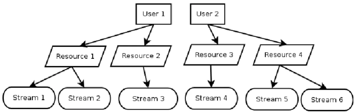
Figure 2-11: IoT Framework User, Resource and Streams ... 30
Figure 4-1 User Interface Flowchart ... 39
Figure 4-2 Management Interface Backend Architecture ... 41
Figure 5-1 Home Page of User Interface ... 44
Figure 5-2 Representation of Machine Device Data ... 45
Figure 5-3 Frontend JavaScript Architecture ... 47
Figure 5-4 Workflow of PHP Application ... 49
Figure 5-5 Controllers and Capillary Network Components ... 50
Figure 5-6 Workflow of Anomaly Detection Program ... 52
Figure 5-7 Sequence Diagram of Pub/Sub Server ... 55
Figure 5-8 Sequence Diagram of Retrieving Device List from PHP Application ... 56
Figure 5-9 Workflow between Node Server, PHP application and Redis Server ... 57
Figure 5-10 LWM2M and PHP application integration ... 59
Figure 5-11 LWM2M example commands ... 59
Figure 5-12 Database table ... 63
Figure 5-13 Demo Environment ... 64
viii
List of Tables
Table 2.1 Most Common HTTP Methods ... 9
Table 2.2 HTTP Status Codes ... 10
Table 2.3 REST architecture implementation example in a Web service ... 11
Table 2.4 CoAP Message Types ... 13
Table 2.5 CoAP Response Code Examples ... 15
Table 2.6 LWM2M Interfaces and Operations ... 18
Table 3.1 Requirements for the Management Interface’s Frontend ... 32
Table 3.2 Requirements for the Managements Interface’s Backend ... 34
Table 5.1 REST APIs towards CNF ... 60
Table 5.2 REST APIs towards CNF used for demonstration ... 61
Table 5.3 REST APIs towards CNM ... 61
Table 5.4 REST APIs towards IoT Framework ... 62
Table 5.5 REST APIs towards vGW ... 62
Table 5.6 APIs towards Pub/Sub server in Capillary Networks cloud ... 63
Table 6.1 Frontend Requirements Evaluation ... 67
Table 6.2 Backend Requirements Evaluation ... 69
Table 6.3 Measurement Results of HTTP Requests for HTML, JS-Core and JS-Google Maps ... 72
Table 6.4 Measurement Results of HTTP Requests for CSS and Images ... 73
Table 6.5 Measurement Results from WebSockets and Browser Memory Use ... 73
Table 6.6 Measurement Results from WebSockets with latency and Browser Memory Use ... 75
1
1
Introduction
The Internet has grown extensively and fast-paced in the last decades, from serving hundreds of hosts to providing billions of interconnected, complex hosting solutions. The evolution of the Internet is still ongoing swiftly with the addition of mobile de-vices in great numbers connecting to the Internet. Interconnected computers and mo-bile devices constitute the current Internet architecture in which the people are con-nected to the Internet regularly.
The next leap in the Internet connectivity is to evolve from connected computers and mobile devices to connected real world objects. Hence, the purpose is to extend the Internet of computers to Internet of Things. Connected things will combine the real world with the digital world, bringing the environmental information from the ob-jects to the use of the complex systems in the Internet. Things in this scope are main-ly constrained devices such as sensors or actuators placed around the daimain-ly environ-ments and they can collect e.g. temperature readings from a room, heart rate readings from a patient, humidity values and many other uncountable environmental infor-mation. The information collected can be processed by different entities in the net-work and different applications can be retrieved from the data. Moreover, things can interchange data between each other to enable different interaction possibilities such as the heating system at home can be turned on automatically when the sensor on the door lock notifies the heaters about incoming home owner or the fridge can send up-dates to its manufacturer for maintenance purposes.
The application possibilities, which the Internet of Things concept offers, are bound-less in industry, home automation, health, logistics or any other area by connecting the things to the network. However, the constrained nature of the things i.e. devices introduces challenges to connect these low-energy, low-processing power and sleepy devices to the network. The current Internet uses mainly HTTP over TCP/IP stack for reliable data transmission in always-connected networks. But the Internet of Things requires specialized methods and communication aspects to tackle the con-nectivity challenges created by the constrained networks.
The research in making the Internet of Things (IoT) real focuses on how to tackle the challenges of constrained networks in different ways and on how to integrate the de-vice and the data to the cloud optimally. These topics are hot topics in many research projects and the Capillary Networks project is one of the research projects which fo-cuses on these research problems and their solutions. Enabling an easily deployable connected devices architecture with using cloud resources extensively is the key ob-jective of the Capillary Networks project.
The number of connected things is expected to be in billions, which is supposed to transform the network to an enormous scale. However, this expected large number of
constrained devices raises another problem in the IoT network: the device manage-ment. Each one of the connected devices needs to be managed and maintained by the network manager either manually or automatically. But the challenges introduced by the connectivity constraints of the devices pushes the research to find new ways of device management for constrained devices, which are different than current Internet entities using always-connected, non-constrained nodes. Hence, the device manage-ment in IoT requires lightweight and innovative methods designed in particular for constrained devices.
The management of an IoT network requires manual interaction with the end user for monitoring the network, even though the entire network management is automated. For this purpose, a device management interface in IoT can be implemented as a Web service, which combines the whole IoT network management aspects such as monitoring, manual device controls, error reporting or data presentation. Web service provides easy integration of the device management to the current Internet, high reachability of the interface and innovative graphical ways to manage the large num-ber of devices.
This thesis presents the requirements, design and implementation of a Web based IoT device management interface for the Capillary Networks architecture to research the solutions for IoT device management problems. The interface combines several IoT-specific aspects with the existing Web architecture to find solution to the re-search statement.
1.1
Objective of the Thesis
The management interface design and implementation consist of three main objec-tives:
1. The management interface is required to be designed so that it can optimally handle large number of devices and large amount of data. Moreover, the fea-tures of the device management should be supported for each single device. 2. The interface is needed to present the features of the Capillary Networks
ar-chitecture to the network manager. To satisfy this, the interface is supposed to gather network management information from different network entities and create the final look. Hence, the interface is required to be designed as a standalone solution.
3. The features specific to IoT device management should be integrated to the interface for constrained network optimization.
To satisfy the objectives, the thesis discusses the implementation of the IoT device management interface done with the use of HTTP, WebSockets, CoAP, LWM2M and specific IoT device management features.
1.2
Scope of the Thesis
The thesis focuses on the design and implementation of a device management inter-face built on top Capillary Networks architecture and integration of Capillary Net-works components. Hence, we omit the integration of other IoT network solutions or protocols which are not used in the Capillary Networks.
The discussion for the implementation of Capillary Network entities is not included as well. The management interface is built upon the existing Capillary Networks ar-chitecture and hence, only the relevant features of the arar-chitecture is discussed. The management interface introduces an online map to display the locations of de-vices (gateways and sensors) on the map. The map is limited to the two-dimensional locations i.e. three-dimensional presentations of device locations are out of the scope. The map is mainly aimed at presenting geographically distributed devices. Moreover, indoor positioning of the devices inside buildings is also not included in the thesis. Furthermore, the management interface assumes the security of the network i.e. the devices and the data is already established by other means or entities. Therefore, se-curity concerns of the IoT network architecture is skipped from the thesis.
1.3
Structure of the Thesis
The thesis consists of 7 chapters. Chapter 2 presents the background information gathered during the thesis research. Chapter 3 introduces the requirements of the management interface implementation while we present the interface design in Chap-ter 4. ChapChap-ter 5 discusses the implementation in detail both for the frontend and backend of the interface. In Chapter 6, we evaluate the interface performance with obtained measurements from the tests. Finally in Chapter 7, we review the thesis by summarizing the outcomes obtained during the thesis and suggest ideas for future work about the thesis topic.
4
2
Background
This chapter presents the related technology and literature relevant to the work de-veloped during the thesis. First, the concept of Internet of Things (IoT) and of device management in IoT is discussed thoroughly. Next, two IoT projects, which we got involved during the thesis, are shortly introduced. Several communication protocols and their roles in IoT device management are also presented, followed by the intro-duction of some data handling solutions in IoT networks. Finally, different features used in IoT device management are presented in detail by referring to related proto-cols or concepts.
2.1
Internet of Things
The concept of Internet of Things is presented in this section with an aim to cover the idea behind this evolving set of technologies. Requirements and challenges encoun-tered in IoT device management are introduced as well, followed by two project overviews.
2.1.1
Internet of Things Overview
The idea of connecting things to the Internet has been discussed and researched ex-tensively by research institutions and industries for the last two decades as the new technology breakthrough. Connecting these things, i.e. physical components, to cre-ate an Internet of Things (IoT) is predicted to have great impact in daily life and will eventually make many applications possible, such as health care tracking, smart homes, smart industrial plants, logistics and many other examples both in the public and private sectors within [1].
M2M (Machine-to-Machine) with a similar concept of connecting things has been in use in different industries since early 1990s [2]. However, M2M and IoT are two dis-tinct concepts: IoT is broader and is an evolution from M2M in terms of ty, application and storage. The main purpose of M2M is to maintain the connectivi-ty between a specific machine and the remote host in a fixed, proprietary installation, which is generally configured to monitor and control only those specific types of
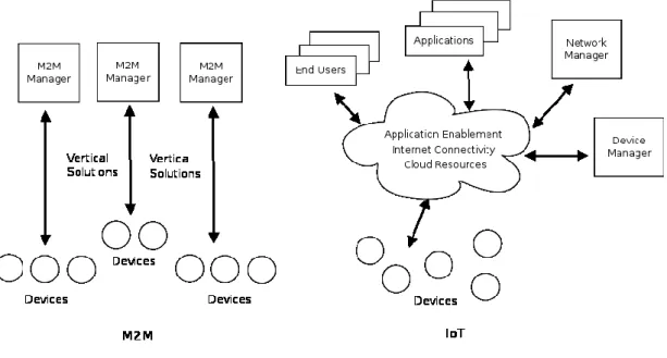
machines i.e. vertical solutions [3]. Hence, M2M provides end-to-end connectivity to send the machine data to the cloud and to manage only specific, closed and point-to-point systems, such as elevator remote control or fleet management solutions [2]. However, IoT concept broadens the idea of M2M to create a new Internet of con-nected things horizontally rather than vertical solutions. To establish the horizontal interaction between IoT entities, things connected to the network send their data to the cloud, from which humans, computer systems and other things read the data, in-teract with each other and integrate with other standalone applications/solutions [4] (see Figure 2-1). Thus, IoT aims at creating an open, scalable, standards-based, ser-vice-oriented network in which very large amount of nodes can communicate and
interact with each other, such as receiving updates from your refrigerator to your mobile phone about the food which will go bad soon, heart beat readings of a patient sent to a monitoring node for notifying the doctor in case of anomaly or the sensors in an oven sending readings to the manufacturer for quality assurance.
Figure 2-1 M2M and IoT Comparison
To achieve the goals set by the IoT vision, new features and methods are to be intro-duced to the already existing M2M solutions, some of which are [2]:
- Connectivity: The small, constrained devices needs to be connected to the network. Since these devices are generally power-constrained non-cellular devices, low-power connectivity solutions are needed.
- Communication Protocols: To decrease the network traffic of the con-strained devices, special concon-strained protocols are needed both for data and control paths since traditional Web protocols (HTTP/TCP) create heavy traf-fic for constrained devices
- IP-Based: Enabling things communicating with each other requires each of them to be accessible in the Internet. IPv6 provides large enough namespace for billions of possible connected devices for this purpose.
- Smart Objects: To store the data and to enable different network elements to interact with it, the data needs to be in a standardized format. This assures in-teroperability between different elements of the network.
- Web APIs: APIs to retrieve the data and other information from the cloud and the network provides ease of integration by other nodes or free applica-tion development on the provided data without the knowledge of the source of the data
- Post-Processing of the Data: The immense amount of data stored in the cloud can be related to other entities or can be processed for developing busi-ness logics. Moreover, the data can be analyzed for anomaly detection, track-ing, data assessment etc.
One of the main purposes of IoT is the construction of a horizontal, versatile, scala-ble and accessiscala-ble data architecture where large number of devices and humans in-teract with each other. However, the vast amount and distribution of the devices over the network creates technical challenges in device management of devices in IoT. Device monitoring and control, network monitoring and management, device or re-source identification and discovery are some of the challenges the infrastructure of IoT is required to find solutions for.
To achieve the management of IoT devices in distributed and constrained networks, specific constrained protocols with IoT specific features are needed. Moreover, the network architecture requires to provide and store the device management infor-mation retrieved from both the devices and the management nodes. The integration of the management protocols and management data to the Internet can be achieved by using Web services, which creates human-readable, interactive management inter-faces.
The device management interfaces are often placed at the end of the IoT manage-ment network and provides all the relevant information to the end user i.e. the device manager. Handling the vast amount of devices and the data, along with several dif-ferent communication protocols and cloud resources, device management interfaces are required to be the wrapper applications in the network combining different proto-cols, features and data handling methods.
2.1.2
Project Overview
During the duration of the thesis, we were involved in two IoT projects, which are Capillary Networks and COMMUNE.
Capillary Networks
Predictions for future IoT architecture propose that billions of devices will be con-nected to the Internet, as stated in the previous section. But the majority of these de-vices are expected to be non-cellular, basic dede-vices (e.g. sensors, actuators) using only short-range radio technologies (Wi-Fi Low Energy, BLE, IEEE 802.15.4 etc). A possible scenario for non-cellular devices to connect to the cellular network is the use of capillary gateways. In this case, a capillary gateway is a device which is capa-ble of communicating over short-range radio and providing network connectivity (ei-ther cellular or fixed network connection) to non-cellular devices. Moreover, a capil-lary network refers to the local short-range network created between non-cellular de-vices and the capillary gateway. By making easily deployable capillary networks possible and creating end-to-end connectivity between non-cellular devices and the end user, capillary networks are supposed to be an important concept for making IoT real [5].
CGWs can be connected to the Internet using either wired or wireless backhaul. For this project, however, LTE was chosen to be the backhaul technology with the moti-vations such as [6]:
fiber cable.
- 3GPP is currently the best solution in case of mobile capillary networks. - Connecting capillary networks to core cellular network enables cellular
net-work features to be used for capillary netnet-works.
The Capillary Networks project aims at providing connectivity to devices connected via CGW, which current 3GPP devices do not support. Following are some other features offered by the project outcomes, which do not currently exist in 3GPP solu-tions:
- Enabling end-to-end management and connectivity over cellular network for very simple and cheap devices e.g. sensors or actuators.
- Smart CGW selection between capillary networks. - Increased QoS for capillary networks.
- Possibility to have middleware with different functionalities in the core net-work for capillary netnet-works e.g. proxies.
- Providing cloud resource optimization for capillary networks management and data.
Features and components of the Capillary Networks project are discussed in detail in Section 2.5.
COMMUNE
COMMUNE is a joint Celtic-Plus project with partners from Finland, Spain, Poland, Slovenia and Ireland. The project focuses on the problem of how to manage future networks under uncertainty and proposes solutions based on cognitive networking techniques to reduce uncertainty with critical management situations [7].
While knowledge based reasoning approaches in order to detect system faults are widely used in current networks, the solutions still include human interaction to deal with uncertainties in complex networks. To decrease the need for human interaction, machine-learning techniques may be relevant to deal with network management un-der uncertainty.
In the concept of COMMUNE, cross domain management should require less human interaction in the future as the number of nodes connected to the network and the amount of data produced will be immense such as the number of IoT devices. From IoT device management perspective, COMMUNE offers automatic anomaly detec-tion in the device data as a cognitive method (see Secdetec-tion 2.4.4).
2.2
Communication Methods in IoT Device Management
IoT device management requires extensive communication of the network manager with the constrained devices and with the other entities in the network. Management commands from the manager are transmitted to the device via different nodes using different communication methods/protocols. Being generally in the cloud as a Web server, the management node is expected to support HTTP [8] to integrate seamless-ly with other cloud entities. Since HTTP does not support real-time communications
directly, the WebSocket protocol can be used between several entities for real-time device monitoring. Moreover, the manager may be limited to use specific protocols to communicate directly with the constrained devices due to low power, connectivity or other constraints. For this purpose, the manager can use CoAP (Constrained Ap-plication Protocol) [9] as a protocol for constrained environments either for data in-terchange from the devices or for management commands. For the management part in particular, a lightweight device management protocol working over CoAP would complete the functionality of the IoT device management. LWM2M (Lightweight Machine-to-Machine Device Management) [10] satisfies the requirement of working over CoAP and retains many features for IoT device management. As it has been shown, there are several different protocols that are needed for IoT device manage-ment to integrate with the rest of the network. This section discusses these communi-cation methods and protocols, which are to be used for a complete and operable IoT device management solution.
2.2.1
HTTP
HTTP (Hypertext Transfer Protocol) is one of the widely used application layer pro-tocols for transferring data over the Internet [8]. HTTP architecture defines a server (generally referred as web server), which serves the data and a client (generally a
web browser), which requests the data from the server. Hence, HTTP follows a re-quest-response scheme i.e. request from the client is sent to the server and the server replies with a respond to the client.
Since HTTP is an application layer protocol, it can be used on top of any reliable transport level protocol such as TCP or RTP [8]. The current web servers in the In-ternet mostly utilize HTTP on top of TCP/IP stacks.
Resources and Path Conversion
The web server stores the web content, which is sent to the client in HTTP response. The web content can include static HTML files, images, messages, videos, on-demand dynamic content and many other types. Each single piece of the web content is defined as a resource on the web server i.e. any content that has an identity on the web server is a resource [11].
Resources on the web server are accessible via uniform resource locator (URL). URLs indicate a reference to the unique resource on the web server and follow the format below [12]:
PROTOCOL://HOST_NAME:PORT /RESOURCE_PATH?RESOURCE_INPUT PROTOCOL refers to the application layer protocol used (e.g. http) while HOST_NAME is the webserver address (e.g. www.ericsson.com). PORT is the port number accepting the requests in the server (80 for default http requests). SOURCE_PATH defines the resource location on the server whereas RE-SOURCE_INPUT is the input given by the user agent for the requested resource. In practice, webserver backend implementation is responsible of directing URLs into
logical functions and of responding the user with the requested resource. Hence, the requested URL may not refer to a simple static file but rather can also refer to a more complex data acquisition in the server.
Methods
As defined in [8], there are six main HTTP request methods which indicate to the server the action to be performed on the requested resource. Each request is accom-panied with one type of method and the method type is written in the request header. The list of HTTP methods is presented in Table 2.1.
The methods available, GET method is the most common one which basically asks the requested resource from the server. GET request data is encoded in the URL it-self. However, the request data is encoded in message bodies in case of POST and PUT methods. The server processes the message data in POST and PUT requests (e.g. written to the database) and returns the appropriate status code. Less common methods HEAD, DELETE and TRACE are mentioned in Table 2.1.
HTTP methods can have two different features, safe or idempotent. A safe method should not modify any data in the server other than just retrieving the information, such as GET and HEAD. To perform changes in the server, “unsafe” methods should be chosen [8]. Moreover, idempotent methods should have the same side-effects in single or multiple requests to the server i.e. the user can send multiple requests to the server while expecting the same server response.
Table 2.1 Most Common HTTP Methods
Method Description Safe Idempotent
GET Get the requested resource. Yes Yes POST Post data to the server for processing No No PUT Store the resource in the server No Yes HEAD Get only the HTTP header, no body Yes Yes DELETE Delete the resource in the server No Yes TRACE Trace the request to the server Yes Yes
Status Codes
Each HTTP request receives a response code from the server indicating the result of the operation performed in the backend. The response code is embedded in the HTTP response. If the server responds with data, the data is attached to the response as
well.
HTTP response code is a 3-digit result code in which the first digit defines the class of the response [8]. The last two digits can be defined depending on the implementa-tion; however, there are widely accepted and used HTTP codes available. The list of status codes are presented in Table 2.2:
Table 2.2 HTTP Status Codes
Class Category Description Example
1xx Informational Request received, continuing the process 101 Switching Pro-tocols
2xx Success The action successfully performed 200 OK 3xx Redirection Further action needed 302 Found 4xx Client Error The request cannot be handled 404 Not Found 5xx Server Error The server failed to fulfill a valid request 500 Internal server
error
2.2.2
REST
Representational state transfer (REST) is an client-server type architectural style for network applications, which consists of several design principles and has defined the current basis of the World Wide Web [13]. Although REST is not a protocol not has been standardized within HTTP standards, the Web architecture has evolved on REST architecture using the distributed system design defined with REST [14]. REST relies on three main design principles: addressability, uniform interface and statelessness [15]. Addressability refers to data elements in the server being accessi-ble via uniform interfaces to the clients. Data elements in REST are abstracted as re-sources, which makes REST a Resource Oriented Architecture [13]. As stated in 2.2.1, resources can be any type of information stored on the server and accessible via a uniform and standard interface (i.e. URI) [16]. Advantages of using a uniform interface are familiarity of the web server operations to the clients and interoperabil-ity of the request and responses [16]. Statelessness of REST architecture assures that requests are performed with the information provided only in that request i.e. the server never relies on the data from previous requests to perform the operation for a new request. Statelessness provides several advantages for implementation such as scalability and load balancing [16].
As mentioned above, REST is widely used in current the Internet applications along with HTTP, though REST can be applied on other protocols as well. Support of ex-tensive representation formats (e.g. HTML, JSON, XML etc.) and HTTP methods as uniform interfaces (e.g. GET, POST, PUT etc.) can be referred as only two of the
main reasons of the wide use of REST architecture over HTTP in web technologies. Web services combine REST architecture to the implementation with the following convention:
- Resources stored on the server are given unique IDs, which are URIs.
- Request from the client identifies the resource by providing the resource ID in the request.
- The representation of the resource is prepared and sent in the response to the client.
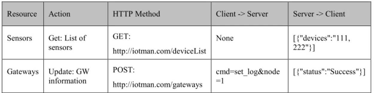
- The requests are not directly referred to previous requests (statelessness). Table 2.3 presents examples of message flows in a web service, which deploys REST architecture.
Table 2.3 REST architecture implementation example in a Web service
Resource Action HTTP Method Client -> Server Server -> Client Sensors Get: List of
sensors GET: http://iotman.com/deviceList None [{"devices":"111, 222"}] Gateways Update: GW information POST: http://iotman.com/gateways cmd=set_log&node =1 [{"status":"Success"}]
2.2.3
The WebSocket Protocol
The WebSocket protocol is a client-server based communication protocol, which en-ables two-way (bidirectional) communication over a single TCP connection between the client (generally a web page or a web browser) and the server [17]. The protocol is developed as part of HTML5 initiative to decrease the complexity of bidirectional communication in the Web and to provide a simpler form of full-duplex connection to also enable server initiated communication.
Bidirectional communication in HTTP can be achieved by the client frequently poll-ing the server for any updates (HTTP pollpoll-ing or HTTP long pollpoll-ing). However, this approach is not efficient with the following reasons [17]:
- For each request, the server needs to use different TCP connections and handshakes.
- Each request repeats HTTP headers and the same applies to the response. - The client needs to map the outgoing HTTP connections to the incoming
connections.
The WebSocket protocol eliminates the need of HTTP polling by the client since the open TCP connection can be used to send information either by the client or by the server. Bidirectional nature of the WebSocket enables the build of scalable and real-time Web applications, in which the server can initiate the communication as well [18].
The protocol is designed to be compliant with the current HTTP architecture of the Web i.e. it runs over HTTP ports 80 and 443 as well as HTTP proxies or other inter-mediate entities [17]. Protocol switch between HTTP and WebSocket is performed during the “handshaking” process. However, WebSocket is not limited to HTTP or any other application layer protocol since it is an independent TCP-based protocol. The WebSocket protocol consists of two parts, from which “handshaking” is the first part. To establish the WebSocket connection with the server and to switch protocol from HTTP to WebSocket, the client sends a handshake request to the server via HTTP, which can look like as follows:
GET /deviceList HTTP/1.1 Host: server.iotmanagement.com Upgrade: websocket Connection: Upgrade Sec-WebSocket-Key: TS4irnQyQTfEfeRKFyqN8g== Origin: http://iotmanagement.com
The response to the handshake request from the server would be as follows:
HTTP/1.1 101 Switching Protocols Upgrade: websocket
Connection: Upgrade
Sec-WebSocket-Accept: J7/IIGO7dfhs8KWl+098tqUDSeE=
A successful handshake creates the TCP connection between the client and the server and utilizes the WebSocket protocol over this connection by switching from HTTP (note the HTTP status code 101 in the response). The second part, “data transfer” follows the successful handshake. The client and the server uses the TCP connection for transmitting data in a bidirectional manner, in which data messages are sent in frames over this connection. One data frame can look like as follows:
{"name":"networkElements","args":["[{"id":"G002127","latitude":59.40442269 ,"longitude":17.95359135,"service":"gateway","vgwip":"1.1.1.1"}]"]}
The standardized API [19] of the WebSocket protocol enabled many WebSocket im-plementations being integrated into existing Web technologies (e.g. PHP, Perl, Py-thon) or into evolving Web solutions (e.g. Node.js). Moreover, server-initiated data transmission feature of WebSocket introduced the extensive use of Publish/Subscribe schemes in the evolving technologies. It enabled servers subscribing to clients or vice versa to inform the other party instantly by sending a notification. The feature of publish/subscribe is a crucial requirement for real-time device management in IoT, as to be discussed in Section 2.4.1.
2.2.4
CoAP
Constrained Application Protocol (CoAP) is a RESTful application layer protocol specifically designed for constrained devices and constrained networks [9]. It de-creases the effects of the difficulties created by the constrained nature of these net-works (e.g. low-power, lossy). CoAP utilizes a request/response based architecture between a CoAP client and a CoAP server while including key concepts of the Web
(similar to HTTP) such as media types, URIs and method types [9]. Moreover, it in-troduces new solutions for M2M specific problems such as resource discovery of the constrained nodes, smaller message overhead compared to HTTP and asynchronous transfer model.
Message Transaction Model
CoAP uses UDP or SMS (Short Message Service) bindings as transport protocol to avoid the overhead created by connection oriented protocols such as TCP. As the protocol stack of CoAP shown in Figure 2-2 presents, CoAP mainly works over IPv6 using 6LoWPAN (IPv6 over Low power Wireless Personal Area Networks) [20] and RPL for multi-hop cases (IPv6 Routing Protocol for Low-Power and Lossy Net-works) [21] as opposed to HTTP over TCP/IP stack. Hence, including HTTP features for constrained devices does not indicate CoAP being a compressed version of HTTP but rather being a re-designed protocol specialized for constrained environments [22].
Figure 2-2 Protocol Stacks of HTTP vs CoAP
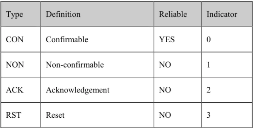
Since UDP is a best-effort protocol, the optional reliability in CoAP is ensured with different types of CoAP messages in the message layer: confirmable (CON), non-confirmable (NON), acknowledgement (ACK) and reset (RST). Confirmable mes-sages require the receiver to send an ACK to the sender to ensure the reliability. However, non-confirmable CoAP messages do not require any ACK. If the response for a CoAP confirmable message is immediately available, the response can be car-ried in the payload of ACK message and this is called piggybacked response [9]. CoAP message types are presented in Table 2.4.
Table 2.4 CoAP Message Types
Type Definition Reliable Indicator
CON Confirmable YES 0
NON Non-confirmable NO 1
ACK Acknowledgement NO 2
Each CoAP message consists of a four-byte binary header followed by a sequence of options and payload (see Figure 2-3). The header contains 2-bit CoAP version, 2-bit message type indicator, 4-bit token length indicator for the variable length token, 8-bit message code (explained in Section “Message Codes and Methods” below) and 16-bit message ID. The header is followed by the token value, which is used to cor-relate requests and responses. Token value is followed by options if there is any. Fol-lowing the options comes the Payload Marker (0xFF) to indicate the end of options and the start of optional payload. This compact header design decreases the overhead significantly compared to HTTP, which leads to decreased energy consumption and response time for constrained devices [22].
Figure 2-3 CoAP Message format
Figure 2-4 presents a communication example between a CoAP client and a CoAP server using CON messages. Response for the CON message is piggybacked in the ACK in both cases while the timeout in CoAP client triggers the request resent to the server in the second case.
Figure 2-4 CoAP request-response example URIs and Discovery of Resources
Since CoAP is a RESTful protocol, information in constrained devices are stored as resources and accessible via URIs. Hence, CoAP defines a URI scheme for CoAP resources (e.g. temperature value in a specific room) which is similar to HTTP URLs (see Chapter 2.2.1):
coap://HOST_ADDRESS:PORT_NUMBER/PATH?QUERY
As an example, following URI refers to the temperature resource on the requested host and the path.
However, machines communicating with each other are required to discover each other’s resources in M2M environments i.e. resources and corresponding URIs are needed to be available for other machines. To solve this problem, CoAP introduces the well-known resource path /.well-known/ in CoAP servers. Each COAP server is suggested to provide the well-known path for resource discovery in the network [9]. The well-known URI is an important aspect for CoAP since it provides uniform and interoperable resource discovery in CoAP networks [23]. For instance, following URI refers to the list of resources in the given host address i.e. to well-known:
coap://[2001:db8::2:1]/.well-known/core Message Codes and Methods
Message code attribute in CoAP message header is used to define different types of request types or response codes. In case of a CoAP request, the attribute is used to determine the message method of the request from one of the following methods:
GET, POST, PUT and DELETE. These methods perform similar way to the same methods in HTTP (see Chapter 2.2.1).
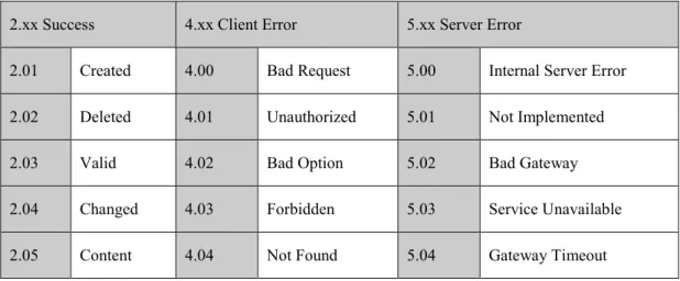
When the CoAP message is a response to a request, 8-bit message code attribute is used to indicate the response codes. Response codes are also similar to HTTP with the difference of a dot between the class of the response code and the sub-class, as some of them are presented in Table 2.5.
Table 2.5 CoAP Response Code Examples
2.xx Success 4.xx Client Error 5.xx Server Error
2.01 Created 4.00 Bad Request 5.00 Internal Server Error 2.02 Deleted 4.01 Unauthorized 5.01 Not Implemented 2.03 Valid 4.02 Bad Option 5.02 Bad Gateway 2.04 Changed 4.03 Forbidden 5.03 Service Unavailable 2.05 Content 4.04 Not Found 5.04 Gateway Timeout
Observe/Notify in CoAP
CoAP introduces an asynchronous publish/subscribe mechanism to enable server-initiated communication, which is called “Observe/Notify” [24]. In HTTP, requests are always client-initiated which means that the client needs to perform the same re-quest frequently (polling) to determine the changes in the server. However, this ap-proach is not optimal for power-constrained environments. To overcome this prob-lem, CoAP enables a communication scheme in which the server can initiate the communication to inform the registered client about the updates in the server data or
management command.
To start the observer/notify mechanism, the client indicates in a CoAP request its in-terest to “observe” the changes in the CoAP server by specifying the “Observe” op-tion in the message opop-tions. This way, the client starts observing the resource on the server and if the resource is updated, the server “notifies” the client with the new in-formation. Notification message is a regular CoAP response (e.g. message code 2.05 Content) with the token ID of the first observe message and an additional observe message ID (see Figure 2-5).
Figure 2-5 CoAP Resource Observe-Notify Scheme
2.2.5
LWM2M
OMA DM Lightweight (LWM2M) is a light and compact device management proto-col that is used for managing IoT devices and their resources [10]. LWM2M runs on top of CoAP as an application layer communication protocol, hence, LWM2M is compatible with any constrained device, which runs CoAP as the transport protocol (see Figure 2-6). The main approach for LWM2M is to provide a set of interfaces for managing the constrained devices. Monitoring, managing and provisioning the mas-sive amount of IoT devices require a standardized lightweight management protocol to maintain the control of the IoT network.
LWM2M offers a simple object based resource model, which allows several opera-tions on the resources, such as resource creation, retrieval (read), update, deletion, configuration, execution, observation and notification [10]. As a device management protocol, LWM2M supports all basic device management functionalities, which in-clude but not limited to access control, firmware update, connectivity, location, de-vice meta data etc. Next sub-sections discuss the architecture of LWM2M and the resource model in IoT device management.
Figure 2-6 LWM2M Protocol Stack Architecture and Interfaces
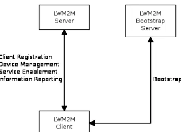
LWM2M architecture defines three logical components:
- LWM2M Client: It contains several LWM2M objects with several re-sources. LWM2M Server can execute commands on these resources to man-age the client, commands such as to read, to delete or to update the re-sources. LWM2M Clients are generally the constrained devices (sensors, ac-tuators etc.).
- LWM2M Server: It manages LWM2M Clients by sending management commands to them. The LWM2M Bootstrap Server configures the access control for a specific LWM2M Server on the constrained device.
- LWM2M Bootstrap Server: It is used to manage the initial configuration parameters of LWM2M Clients during the bootstrapping process. It is only entitled to configure the device to give access to specific LWM2M Servers, hence, management of the device does not involve the bootstrap server after the bootstrap process.
To maintain the communication between mentioned components above, following LWM2M interfaces are defined in the standard:
- Bootstrap: LWM2M Bootstrap Server sets the initial configuration on LWM2M Client when the client device bootstraps. For this interface, the cli-ent sends a “Request Bootstrap” message to the bootstrap server and the server performs “Write” and “Delete” on the client’s access control objects to register one or more LWM2M Servers.
- Client Registration: LWM2M Client registers to one or more LWM2M Servers when the bootstrapping is completed.
- Device Management and Service Enablement: LWM2M Server can send management commands to LWM2M Clients to perform several management actions on LWM2M resources of the client. Access control object of the cli-ent determines the set of actions the server can perform, which is already set during the bootstrapping process.
- Information Reporting: As a feature of CoAP Observe-Notify mechanism [24], LWM2M Clients can initiate the communication to LWM2M Server and report information in the form of notifications.
Figure 2-7 presents the LWM2M architecture and the interfaces between the compo-nents, while Table 2.6 shows all available operations on LWM2M objects in each
interface.
Figure 2-7 LWM2M Components and Interfaces
Table 2.6 LWM2M Interfaces and Operations
Interface Direction Operation Bootstrap Uplink Request Bootstrap Bootstrap Downlink Write, Delete
Client Registration Uplink Register, Update, De-register Device Management and
Ser-vice Enablement
Downlink Create, Read, Write, Delete, Execute, Write Attributes, Discover
Information Reporting Uplink Notify
Information Reporting Downlink Observe, Cancel Observation
Object and Resource Model
The information in LWM2M Clients is stored as Resources and Resources are grouped into different Objects on the client. Hence, a LWM2M Client may have any number of Resources, each of which are grouped under an Object (see Figure 2-8).
Figure 2-8 LWM2M Client, Object and Resource Overview
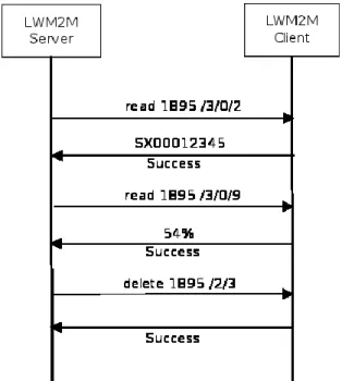
LWM2M Server performs the operations mentioned in Table 2.6 on the objects and resources to manage the device and its resources. Hence, the server can perform any allowed operation on the client. For example, LWM2M Server can read “Serial Number” resource (ID 2) or “Battery Level” resource (ID 9) from Device Object (ID 3) of the client with the ID 1895 (see Figure 2-9). Moreover, it can also delete the “Access Control Owner” resource (ID 3) from Access Control Object (ID 2) (see Figure 2-9).
The format of LWM2M objects is standardized by IPSO (IP Smart Objects) Alliance [25] to ensure the interoperability of the objects between different applications and environments.
2.3
Data Handling for IoT Device Management
Section 2.2 discusses the communication methods to be used for management of many IoT devices and the possible ways to move the data or management infor-mation from the constrained device to the management nodes and vice versa. How-ever, the format of transmitted data also retains critical importance since the re-sources (power, connectivity, processing capability) are limited at the constrained node. Hence, the data formats used to communicate with the constrained device for the data exchange are required to be lightweight and versatile for optimum resource consumption. Moreover, the large amount of data from the many constrained nodes readings needs to be stored in the cloud for post-processing purposes (data analysis, error/anomaly detection, pattern recognition etc.). The storage method of the data determines the practicality and methodology of how the post-processing functions are performed. For these purposes, a store model (NoSQL) and a data-transmission/store model (JSON) are discussed in this section.
2.3.1
NoSQL
The large amount of data created by the emerging technologies (IoT, Mobile or Cloud Computing) has created new expectations from database management sys-tems, which traditional relational database designs (e.g. MySQL, PostgreSQL) do not possess: high concurrent reading and writing rates, high scalability and availability, dynamic schemas, efficient very large data storage, easiness to expand and distribut-ed architecture [26]. To satisfy these expectations for Big Data management, new type of database systems, which are very different than relational databases in de-sign, have appeared and are referred with the term NoSQL (Not Only SQL) in gen-eral.
The design of NoSQL databases can be different from each other but each one of them shares similar advantages over relational databases:
- Schema-free: Relational databases require a fixed table (relation) defined be-fore storing data (e.g. rows, columns, tables). If a new type is added to the table, the entire database must be re-altered. However in NoSQL databases, either new data values or new data types can be added dynamically without altering the entire database leading to great flexibility [27].
- Horizontal Scalability: Relational databases are vertically scalable, which is a single-server model for the host machine while NoSQL databases are hori-zontally scalable, meaning the load can be distributed automatically between different hosts without any complicated configuration procedure [28]. Hori-zontal scalability provides diverse distributed NoSQL databases.
- Eventual Consistency: NoSQL databases can support very high rate of con-current create, read, update and delete (CRUD) operations effectively [29].
NoSQL databases are grouped into different groups according to their design archi-tecture, some of which are:
- Key-Value Store: A key value corresponds to a value like a dictionary, without any structure or relation. Any type of information can be stored in either key or value attribute. Each key or value can store different data struc-ture than other key-value pair, which provides high flexibility, scalability and faster query than SQL databases. Some example implementations are Redis, MemcacheDB, Oracle NoSQL etc.
- Document Based: The structure is similar to key-value store NoSQL but the value of the key is stored as a document in either JSON or XML format. This approach enables complex structured information trees to be stored in docu-ments. Some examples are MongoDB, Elasticsearch, Couchbase Server etc. - Column Oriented: The structure is similar to key-value store too. However
in column oriented NoSQL databases, each key can be associated with one or more key-value pairs constructing a two-dimensional array i.e. value of a key can be another key-value pair. This nested, unstructured data architec-ture allows very large, aggregated data storage possibility. Examples include Cassandra, Hadoop (HBase), Apache Flink etc.
- Graph Based: The architecture is based on tree-like structures (i.e. graphs) where the objects (the data) are connected to other objects through static or dynamic relations. The data pieces are connected to each other and the rela-tions between the objects are used to retrieve the data. Social networks (e.g. Facebook, LinkedIn) can be modeled as graph based databases. Some exam-ples are OrientDB, Neo4J, Infinite Graph etc.
Different type of NoSQL introduces different type of advantages for IoT data storage over relational databases. For this thesis, several type of NoSQL databases are used for different purposes (see Section 2.5.2 IoT Framework and Section 5.2.3).
2.3.2
JSON
JSON (JavaScript Object Notation) is a widely used, lightweight, text-based, lan-guage-independent data exchange format [30]. It provides a nested data structure format for interchanging complex data structures but still is simple to parse even by the constrained devices considering the low overhead in JSON messages and JSON parsers requiring very little processor power.
JSON defines four primitive types: strings, numbers, booleans, null and two struc-tured types: objects and arrays [30]. Objects can be other JSON messages inserted into the outer JSON message so that nested JSON objects can be created. Moreover, JSON supports arrays of any supported format (i.e. strings, numbers, booleans and objects) to be created. Both arrays and objects assure a detailed, structured model for aggregated data interchange. An example JSON message is presented below:
{
"node": “2”,
“devices”: “280:e103:1:2a9c”, "params": {
"lat": 41.35342516, "lng": 2.13135839, "280:e103:1:2a9c ": { "lat": 41.35361845, "lng": 2.13043571, } } } }
Being lightweight makes JSON a good candidate for IoT device management mes-sage interchange format because many constrained devices can parse JSON messag-es without much power consumption. JSON mmessag-essagmessag-es can be attached to CoAP pay-load and LWM2M resources can be retrieved as JSON as well. Web services utilize JSON heavily since JSON integrates very well JavaScript. Hence, using the uniform JSON as the data interchange format in all protocols (CoAP, LWM2M, HTTP) de-creases the complexity of integration between constrained environments and the Web significantly.
2.4
Features of IoT Device Management
The constrained environment in IoT devices and networks imposes IoT device man-agement schemes to introduce the IoT-friendly (i.e. low power consumption, low processing power, lossy networks) management features. For instance, frequent poll-ing of data from low-power devices is not optimal for power consumption and the IoT device management is expected to avoid such situations. In this section, we dis-cuss several features of IoT device management which are addressed to optimize the use of constrained environments and to maximize the IoT data readings.
2.4.1
Publish/Subscribe
Publish/subscribe is a paradigm discussed in the concept of Information Centric Networking (ICN). ICN redefines the network purpose to provide information dis-semination throughout the highly scalable distributed nodes rather than to provide pair-wise communication between the end points [31]. In the data-oriented network definition of ICN, data distribution between nodes can be achieved by nodes sub-scribing to information updates on other nodes and information being published to the subscribers by the information source [32].
The large number of IoT devices, the amount of data and management commands transmitted and the constrained environment of the devices make Publish/Subscribe mechanism a valuable solution for data distribution in IoT networks. Several reasons can be enlisted as why the Publish/Subscribe approach in ICN should be applied in IoT device management too:
- Data retrieval from power-constrained devices is a challenge since common polling mechanisms towards the device create unnecessary connections if the data on the device has not changed. Hence, the optimum way is the device ‘informing’ the network only if the data on the constrained device changes. This can be achieved by the network nodes subscribing to the device (the publisher) and it decreases the power consumption dramatically.
- The data retrieved from the device can be applied to several processes in the network, such as aggregation and abstraction, and the result of these proce-dures is transmitted to other entities. The information can be delivered with Publish/Subscribe scheme for event-driven, flexible data management to en-sure scalable and dynamic network topology [33]. This approach proposes IoT networks to be an important part of ICN i.e. the Future Internet.
- Publish/Subscribe schemes introduce loosely coupled, asynchronous rela-tions between the publisher and the subscriber [34]. The loosely coupled re-lation between the publisher and the subscriber permits the IoT device man-agement to scale the manman-agement resources optimally in the cloud. Howev-er, the device management is required to track the list of subscribers and publishers in such case.
Considering the REST approach of client requesting the information from the server is not the efficient way to distribute the data in the constrained networks, CoAP in-troduces Publish/Subscribe paradigm as Observe/Notify for constrained devices [24]. Any client can observe any resource stored on the device and notifications are sent for information updates from the CoAP server (see Section 2.2.4 Observe/Notify in CoAP). Moreover, LWM2M supports Observe/Notify scheme as well since it runs on CoAP (see Section 2.2.5).
Observe/Notify scheme in CoAP and LWM2M introduces the advantages of Pub-lish/Subscribe discussed above to IoT device management. Moreover, event-driven approach of Observe/Notify provides real-time network monitoring and controlling in IoT networks. Network manager by observing the resources on the device is noti-fied instantly for information updates such as errors, logs, network topology changes and data updates, which is an important asset for real-time IoT device management.
2.4.2
Aggregation
Constrained characteristics of IoT devices require the management nodes of the IoT networks to be smarter to decrease the power consumption and processing required on the device [35]. Aggregation of data and management commands is one of the ways to achieve that target by means of decreasing the communication with the de-vice and implementing the aggregation logic in the network.
In data aggregation model, the data from the device can be aggregated in different parts of the network before reaching to the cloud storage. A gateway or a proxy in the network aggregates the data from different resources according to the characteris-tics of the data such as the devices in the same neighborhood, same type of devices or similar data reading values. This type of aggregated data simplifies the post-processing data analysis by giving the insight about the entire set of data rather than individual data points [36]. It as well decreases the total amount of messages for the data points by grouping them into one message.
Aggregation of management commands implies a more important aspect for IoT de-vice management. The network manager can send aggregated, different management commands to e.g. gateways and gateways capable of interpreting them split the
mes-sages to be sent to different machine devices. This decreases the traffic on the net-work since the several management commands are transmitted in one aggregated message. Moreover, grouping the devices and gateways to manager-defined clusters also allows the manager to send one group message to the entire group. Different from the aggregated message, group message is defined to be the same for the group elements. The distribution of the group message to each group element is performed in the network node where the group information is stored such as in a gateway or a proxy. During the research for this thesis, several patent applications have been pre-pared regarding the aggregation and group management for CoAP and LWM2M. The main target of both aggregated and group messages is to decrease the communi-cation required in the network by combining several messages, which leads to less power consumption and a more compact communication model.
2.4.3
Prioritization
As stated in Section 2.4.2, IoT device management nodes are required to be smart to increase the efficiency of the constrained networks. Prioritization of the messages in the network is yet another way to achieve that target.
Prioritization in communication networks allows several possibilities for different types of messages: High priority messages must reach the destination, medium prior-ity messages are important but less sensitive to delay while low priorprior-ity messages are less important with additional data [37]. To take the message priorities into account, new features can be added to routing protocols such as priority queues in each node or identity based priority assignments [37] [38].
The concept of prioritization in IoT device management indicates that either the management server or other entity in the network assigns different priority levels for messages transmitted to/from the device (e.g. CoAP or LWM2M messages). Each message with its own priority level allows the network entity (e.g. gateway, man-agement node etc.) to classify the messages and act according to those levels. For instance, critical error messages from the device can be assigned high priority and can bypass the possible queues in the proxies, any aggregation node or re-routed in case of congestion to the management node. Similarly, firmware updates from the LWM2M server can be prioritized for critical security updates as well.
The critical asset the prioritization introduces to IoT device management is the sup-port of classified messages. This implies additional benefits for real-time device management, increased monitoring and controlling capability over the entire IoT network.
2.4.4
Anomaly Detection
Constrained devices, typically sensors or actuators, transmit their data readings to the network frequently and the amount of the entire data becomes massive considering the large amount of devices. However, data readings of the devices can encounter anomalies due to the device hardware problems or other external factors. The device may not send any error messages regarding this; hence, the management node is
re-quired to detect the anomalies only from the acre-quired data readings in that case. There can be several reasons why the device data readings can encounter anomalies, such as sudden, short time temperature increase in a temperature sensor due to exter-nal heat or light sensor displaying light appearance in a dark room. Thus, anomalies do not always refer to hardware or software errors on the device but can refer to unu-sual, abnormal environmental factors.
Detecting the possible anomalies is an important asset for the IoT device manage-ment to ensure the reliability of the data. The acquired data readings from devices are used for post-processing, analysis and decision-making. Hence, the users of the data should be assured about the data reliability, which can be achieved by anomaly de-tection algorithms.
The challenge is, though, the amount of the data and the variety of the data sets. Anomaly detection algorithms are generally sequence or pattern based, which use statistics, classifiers or machine learning techniques to detect the anomalies [39] [40]. With the immense variety of IoT device data types, it is still a big challenge to perform anomaly detection in any type of data i.e. anomaly detection algorithms are tailored for specific types of data sets, which creates integration complexity for other sets of data. At the time of the research, anomaly detection in IoT is still an immature topic. However, IoT device management can include anomaly detection support for a specific type of data set for the proof of concept work.
2.4.5
Error Reporting
Machine devices are generally geographically wide-spread, which makes them un-reachable in case of an error on the device. This introduces the need of remote error monitoring for IoT network. However, machine devices are not connected to the network all the time, which might lead to latencies in error reporting. Hence, IoT de-vice management requires a solution for error reporting of the machine dede-vices and gateways.
For an efficient and versatile error reporting mechanism, use of already existing sys-tems rather than introducing a new protocol decreases the integration complexity. CoAP and LWM2M systems provide a great basis for building such an error report-ing mechanism for IoT devices. Use of CoAP Observe/Notify scheme together with relevant objects and resources of LWMWM clients (e.g. device battery level re-source, connectivity error resource etc.) is a great way of real-time error reporting for IoT devices in the already existing architecture i.e. device management interface can observe relevant resources on LWM2M client for instant error monitoring.
As a combined solution of Publish/Subscribe scheme and LWM2M objects, real-time error reporting is an important feature of an IoT device management interface.
2.5
Capillary Networks
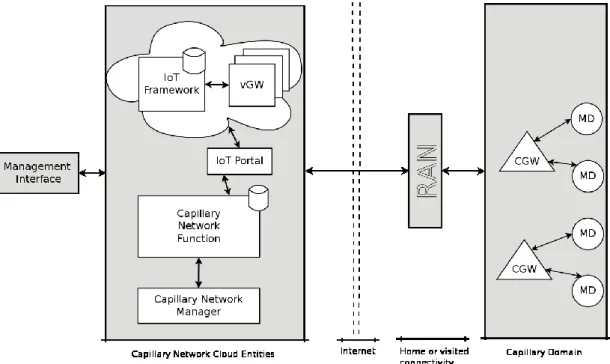
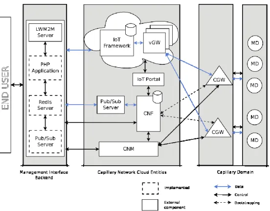
In order to provide end-to-end IP connectivity for Capillary Networks (see Section 2.1.2) and constrained devices in the real world, a high-level network architecture