http://www.autexrj.com/No2-2012/0006_12.pdf 29
OPTIMISATION OF THE WARP YARN TENSION ON A WARP KNITTING MACHINE
Vivienne Pohlen, Andreas Schnabel, Florian Neumann, Thomas GriesInstitut für Textiltechnik der RWTH Aachen University, Germany
Otto-Blumenthal-Str. 1, D-52074 Aachen, Phone: +49 (0)241 80 23462, Fax: +49 (0)241 80 22422, E-Mail: [email protected], [email protected]
Abstract:
Investigations (calculations) based on a warp yarn tension analysis on a warp knitting machine with multiaxial weft yarn insertion allow prospective reduced yarn tension differences in technical warp knits. From this a future opportunity is provided to substitute the subjective warp let-off adjustment by a model of tension control. The outcome of this is a higher reproducibility with associated increasing process reliability and rising product quality.
Key words:
Multiaxial fabric, non-crimp fabric (NCF), warp knitting machine, warp yarn tension, yarn tension control.
Initial situation
Increasing political pressure is demanding that industry now always produces environmentally sound products. The automobile sector is developing more powerful, lighter electric vehicles (e.g. Megacity Vehicle, MCV). The MCV of BMW in cooperation with SGL Automotive Carbon Fibers is based upon a composite construction of steel, aluminium, and CFRP (carbon fibre reinforced plastic) of 40% [1]. The aviation and aerospace industry is working on lighter aircraft which enable lower operating costs and result in reduced fuel and CO2 emissions. The new Airbus A350 will consist of approximately 55% CFRP. Materials such as CFRP or GFRP (glass fibre reinforced plastics) provide light weight with low density (20-30% lighter than aluminium), and high stiffness while providing strength and durability [2]. High-tech fabrics can significantly contribute to weight reduction. These benefits involve high costs: expensive raw materials (especially carbon fibre) and the high cost of manual production. Automated systems for cost-effective mass production would ensure a consistent product quality. This goal and a more homogeneous NCF-processing (non-crimp fabric, warp knitted multiaxial layers) are dealt with in this present work. It describes the approach, compensating the fluctuating warp tension on a warp knitting machine with multiaxial weft insertion. This is important because different tensions have different effects on the NCF quality, among others, poorer resin permeability, and lower maximum tensile strength initiated, for instance, by stronger undulations.
In the future, a control system may provide for almost constant warp yarn tension, resulting in a reproducibility of the products to ensure consistent quality.
State of technology for the production of NCFs
Textile products are technically versatile. For example, in the A350 the fuselage structure and the engine fixtures are made of CFRP. The fuselage is exposed to lateral or vertical gusts and the undercarriage manoeuvres with a constantly varying load. Therefore, multiaxial fabric is used, which allows variable reinforcement effects [3].
The manufacturing and processing of NCF currently requires a high level of manual operational action. Generally NCFs are
warp knitted glass or carbon fibre layers. These are made on warp knitting machines with multiaxial weft insertion. These enable the production of NCFs for different applications by adjusting several parameters.
A detailed study regarding various adjustable parameters on such a machine has not occurred in previous works. A basis for this is provided by warp tension studies on conventional warp knitting machines. Research projects at the ITM of the TU Dresden showed maximum tensile forces with peak amplitudes of more than 50 cN per warp yarn. The maxima occurred at the point in time when the guide needle does the overlap in the knitting process [4] [5]. J. Hausding conducted research with the Malimo 14022 P2-2S bonding machine with parallel weft insertion (Karl Mayer Malimo Textilmaschinenfabrik GmbH, Chemnitz) to produce a biaxial stitch-bonded fibre layer regarding an extended warp knitting process. He studied, amongst others, the warp yarn tension, but only with respect to their maxima averaged without regard to the tension curve during one-stitch formation [6]. The results show that these values are not comparable with those in this work. In terms of technical progress, it is necessary to incorporate here other parameters or variables and the exact warp yarn tension curve during the one-stitch formation cycle. Currently, the operator adjusts the already stored positions via the CNC machine panel. Parameters such as the mass per unit area of glass layers or the warp yarn tension can be added subjectively and vary depending on experience. The operator feels the warp yarn tension whilst the machine is running. Since this varies within a stitch formation, an accurate assessment is not possible, mainly because the operator perceives the stress peaks. Thus, the human intervention in the repetition of positions leads to non-identical products.
Experimental procedure: measurement of the
yarn tension
In this study, glass fibre rovings (600 tex) were warp-knitted with polyester fibres (175 dtex) on a Copcentra MAX 3 CNC (LIBA Maschinenfabrik GmbH, Naila). The two active weft carriage systems laid the roving into the transport chain at an angle of ±45°.
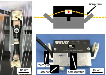
To measure the warp yarn tension, in total six piezoelectric yarn tension sensors (TS 44/A100, BTSR International S.p.A.,
Olgiate Olona, Italy; Figure 1) were mounted along the machine width, above and below the yarn tensioning device. The same yarn ran through two sensors. For the purpose of mapping the extremely fluctuating tension amplitude, it was necessary to determine the exact time of its origin during the warp knitting. Two additional LVDT-displacement sensors (WA / 200 of Hottinger Baldwin Messtechnik GmbH, Darmstadt) measured the movement of the guide bar.
2. Main shaft angle 20°: Falling yarn tension – The compound needles rise gradually and release more yarn. Yarn is delivered continuously.
3. Main shaft angle 160°: Re-falling yarn tension – Overlap of guide needles takes place and expands slightly more than the yarn delivered.
4. Main shaft angle 300°: Extreme rise of yarn tension – The compound needles sink, begin to pull down the yarns and each yarn is laid down on the sinkers.
5. Main shaft angle 345°: Tension drops abruptly – The still sinking compound needles pull the yarns. Meanwhile, the fabric take-up pulls the warp knitted glass layers, which forces the stretched yarns to fall off the sinkers. This briefly causes loose yarn tension.
6. Main shaft angle 350°: Immediate re-rise of tension – The compound needles finish sinking and tighten the yarns, but will not exceed the previous amplitude due to generated yarn storage on the sinkers which were released by dropping.
Depending on the machine parameters set, different characteristic tension curves result. On the one hand, the amplitudes increase or decrease, on the other hand a number of intermediate or no amplitudes are visible. The amplitude level and the different runs depend on the intensity and type of parameters selected.
Influence of parameters on the warp tension
As mentioned already, the greatest yarn tension is initiated by the sinking movement of the compound needles (cast-off – starting underlap). This depends on the set position.
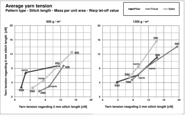
Alternating machine speed has little effect on the yarn tension, which has a linear relationship to the machine speed accelerated yarn delivery. By contrast, pattern, stitch length, mass per unit area and warp let-off have distinctive impacts. With increasing underlap (pillar to satin), the average yarn tension increases (Fig. 3). Throughout the underlap, the guide needle movement takes place at large distances, such as satin, with higher acceleration than at short distances. This difference is not considered in the yarn supply, since the warp beam drive does not respond within a stitch course. The yarn tension increases with smaller stitch length (2 mm) by trend. The reason is that the yarn supply is much lower for the entire warp knitting process as compared to a large stitch length (6 mm). For the moment of different stitch length formation, for 6 mm stitch length a larger amount of yarn is available than for 2 mm. An increase of the mass per unit area of the in-running glass layers causes an increase in average yarn tension due to the increased friction between the warp yarns and the thicker glass layer.
A separate parameter in the experiments is the warp let-off value. For each new position, the value was set subjectively by the operator. Subsequently, the individual parameters are to be regarded as tendencies (see outliers in Fig. 3). The position change from tight (min) to loose (max) set shows significant differences in tension. The tension minima for loose settings reach almost 0 cN, which may lead to process problems: The yarns cannot be guided accurately enough around the warp knitting elements. The same applies to tight settings, which lead to machine shutdown triggered by the yarn tensioning device and stress the warp yarn. Various warp let-off values are clearly perceivable in the textile appearance and lead to different displacement strengths of the glass layers. The linear yarn tension curve by trend (according to Fig. 3) assists in the
12 mm Warp yarn Offset switch Yarn guide 15 mm Fastener
Figure 1. Piezoelectric yarn tension sensor with fastener.
The following parameters with a foreseeable major influence on the tension were realised in the trials: pattern, stitch length [mm], glass layer mass per unit area [g / m] and warp let-off [mm / rack1] (amount of delivered yarn per main shaft revolution
or stitch course, see Table 1). The material composition of the warp yarns and the running-in layers were kept constant throughout the entire experiment.
Table 1. Experimental parameters
Parameter Level 1 Level 2 Level 3
Pattern (determines
underlap length) Pillar Tricot Satin
Stitch length, mm 2 4 6
Machine speed, U / min speed Crawl 135 250
Mass per unit area, g / m² 600 - 1200
Warp let-off, mm / rack subjectively set
“Min”
(tight) “Medium”
“Max” (loose)
Evaluation and processing of the measurement
series
All the sensors’ measured values were recorded using LabVIEW software (National Instruments Germany GmbH, Munich). Analogue or digital filters were not used in order not to distort the useful signal. The series of measurements of all the sensors were processed using Fourier analysis. This process enabled the elimination of high-frequency disturbances such as machine vibrations. Thus the actual useful signal could be better evaluated.
Figure 2 shows the run of warp tension in dependence on the main shaft angle at a speed of 250 U / min. One stitch course is formed during one main shaft revolution (360°, corresponding to a duration of 0.24 sec per revolution). Striking points for the different yarn tensions are:
1. Main shaft angle 0°: Maximum yarn tension occurs (in this case about 11 cN) – The compound needles are in the lowest position and pull more yarn as delivered.
http://www.autexrj.com/No2-2012/0006_12.pdf 31
development of a mathematical correlation for the required loop length for various parameters.
Algorithm for calculating the required loop length
in the NCF and the delivered quantity of yarn,
depending on machine parameters
The tension must be balanced by the warp let-off value. It is greater, the longer the stitch length, the underlap and the greater the mass per unit area are. In order to deliver an optimized
yarn amount for the NCF, a model for determining the quantity of yarn per stitch course has been developed. The previously set values are based on the yarn feeding unit mm per rack. The warp let-off values are set subjectively, but do not always lead to optimum yarn tension. Therefore, knowledge of the required thread length is necessary so that the extremes of the yarn tension can be diminished.
Based on a previous model for loop length calculation in the conventional warp knitting process, the new model has been developed by using elliptical geometrical shapes.
-2 -1 0 1 2 3 4 5 6 7 8 0 2 4 6 8 10 12 14 16 18 20 0 40 80 120 160 200 240 280 320 360 400 440 480 520 560 600 640 680 720 G u id e b a r m o v e m e n t [ V ] r e s p e c tiv e ly [c m ] Y a rn t e n s io n [ c N ]
Machine main shaft angle [°]
Warp yarn tension
Tricot - 250 rpm - 6 mm - 600 g/m²
Mean value original Mean value 6. order Guide bar swinging Guide bar shogging 53th period moving mean
2 3 345° 315° 255° 195° 120° 60° 0° Approximated needle motion 1 4 5 6
Figure 2. Warp yarn tension (Comparison of original vs. 6th Fourier series and moving mean considering guide bar movement).
min norm max min norm max min norm max 0 4 8 12 16 20 0 4 8 12 16 20 Y a rn t e n s io n r e g a rd in g 6 m m s ti tc h l e n g th [c N ]
Yarn tension regarding 2 mm stitch length [cN]
Average yarn tension
Pattern type - Stitch length - Mass per unit area - Warp let-off value Pillar Tricot Satin
600 g / m² min norm max min norm max min norm max 0 4 8 12 16 20 0 4 8 12 16 20
Yarn tension reagrding 2 mm stitch length [cN] 1200 g / m²
The conventional loop length calculation [7] adapted to NCFs is made up of individual components (lk, lu, ls, dg). The length is calculated from the fractions as they are to be found in the finished NCF. The formula for calculating the conventional loop length plus glass layer thickness (1) does not consider the actual underlapping length [8]:
(1)
where: L - conventional loop length [mm], lh - head length [mm],
lu - underlap length [mm], ll - leg length (regarding stitch length) [mm], tl - thickness of glass layers [mm], tn - thickness of warp knitting needle [mm], ρl- stitch density [cm-1], E - machine gauge [number of needles / inch].
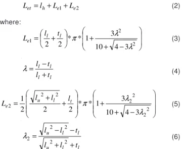
A more realistic model takes into account the length of the glass layer thickness (2, elliptical parts) and the guide bars offset applying the Pythagoras theorem (Fig. 4):
(2) where: (3) (4) (5) (6)
where: Let - total elliptical loop length [mm], Le1 - elliptical circumference applied on both leg [mm], Le2 - half elliptical circumference including underlap distance [mm].
The elliptical model provides more accurate delivery values (average tension for all positions). Slight deviations with regard to the stitch length of 2 mm (see underlined values in Table 2) occur, where the calculation result is too low. The source of this is presumably the large displacement of the guide bar at small stitch length. Due to the high level of correlation with the adjusted values, the yarn Let-values serve as a reference point (Table 2).
Table 2. Comparison of loop length – Set warp let-off vs. calculated
warp let-off per stitch.
l l n l l u h t E t t l L l L 1 2* 1 2* 2 . 2 * * 2 * 2 + = + + + + + =
ρ
π
2 1 e e h et l L L L = + + − + + + = 2 2 1 3 4 10 3 1 * * 2 2λ
λ
π
l l e t l L l l l l t l t l + − =λ
− + + + + = 2 2 2 2 2 2 2 3 4 10 3 1 * * 2 2 2 1λ
λ
π
t l u e l l l L l l u l l ut
l
l
t
l
l
+
+
−
−
=
2 2 2 2 2λ
Head Legs Underlap Glass layers ±45° Layer thickness Direction of production Legs UnderlapGlass layers ±45° Head
Direction of production
Figure 4. Scheme of the conventional (rectangular) and elliptical
geometry. Pattern Stitch length, mm Layers thick- ness, mm
Set warp let-off per stitch, mm /
stitch
Calculated warp let-off per stitch Let, mm / stitch Pillar 2 0.5 7.50 7.29 Pillar 4 0.5 13.02 13.10 Pillar 6 0.5 19.27 19.02 Tricot 2 0.5 10.83 9.84 Tricot 4 0.5 14.58 14.7 Tricot 6 0.5 20.63 20.33 Plain 2 0.5 15.42 13.83 Plain 4 0.5 18.54 18.39 Plain 6 0.5 23.44 23.35 Satin 2 0.5 19.58 17.97 Satin 4 0.5 22.71 22.32 Satin 6 0.5 27.08 27.01 Pillar 2 1 7.92 8.12 Pillar 4 1 n.a. 13.69 Pillar 6 1 20.10 19.48 Tricot 2 1 11.56 10.57 Tricot 4 1 n.a. 15.42 Tricot 6 1 21.25 20.78 Satin 2 1 20.42 18.62 Satin 4 1 22.92 22.81 Satin 6 1 27.81 27.41
Represented as a graph, a linear equation system (7) is obtained for each pattern type, depending on the stitch length by the table values (see Figure 5).
This can be set up for each pattern type. Other components such as stitch length, and loose / tight yarn tension can be incorporated to ensure an optimized tension:
(7)
where: y - loop length [mm], a - gradient, x - stitch length [mm],
b - zero-crossing, ba - additional layers [%], c - warp let-off (tight / medium / loose) [%].
This approach is also applicable to other pattern types not examined (e.g. plain), as the curve run is very similar.
Conclusion and outlook
The investigations show different levels of influence of each parameter set to the warp yarn tension. In particular, pattern type and stitch length have a great impact on the yarn tension
c b b x a y= * + + a+
http://www.autexrj.com/No2-2012/0006_12.pdf 33
maxima and their curve runs. The constant subjective adaptation of the warp let-off values for each position change by the operator complicates comparison of the other parameters. Thus only a tendentious comparison is possible. Nevertheless, the development of an algorithm was successful for optimized yarn delivery broken down to one stitch course. This equation now forms the basis for further mathematical calculations regarding homogenization of the warp yarn tension. Technically, this can be realized by controlling the warp let-off value. The required variables for this are described in this work.
To isolate the influence of the warp let-off on the yarn tension, an analysis with constant yarn tension is reasonable. This should allow a more homogeneous yarn tension development. In addition, a further extension of the yarn tension boundaries is reasonable in terms of improved processability and an expansion of the current NCF scope. Similarly, textile testing is essential to detect improved displacement resistance, handling optimisation and tensile strength.
References:
1. “Carbon Composites e.V. bringt Autobau mit Automotive Forum voran” – http://www.b4bschwaben.de/nachrichten/ augsburg_artikel,-Carbon-Composites-eV-bringt-Autobau-mit-Automotive-Forum-voran-_arid,105196.html. 2. Voggenreiter, H.; Wiedemann, M.; Hirzinger, G.; Dudenhausen, W.; Meyer, M.: “Challenges in Production of Carbon-Fibre Reinforced Aero-structures” – DLR Center for Lightweight Production Technology, German Aerospace Center, DLR Aerodays, Madrid, March 2011.
3. Dudenhausen, W.: “Automatisierung und Qualitätssicherung in der Produktionstechnik im ZLP-Augsburg” – 1. Augsburger Produktionstechnik Kolloquium, Institut für Bauweisen- und Konstruktionsforschung, Abteilung für Rechnergestützte
yP= 2.93x + 1.41 yT= 2.62x + 4.52 yPl= 2.38x + 9.0 yS= 2.26x + 13.4 0 2 4 6 8 10 12 14 16 18 20 22 24 26 28 30 0 1 2 3 4 5 6 7 L o o p l e n g th [ m m ] Stitch length [mm]
Theoretical loop length
ܮ
ܮ
ܮ
ܮ
݁݁݁݁ݐݐݐݐvs. stitch length
of all pattern types (600 g / m²)
Pillar Tricot
Plain Satin
Figure 5. Theoretical loop length Let vs. stitch length.
Bauteilgestaltung, Stuttgart, kom. Leiter Zentrum für Leichtbauproduktionstechnologie Süd, Augsburg, May 2011.
4. Ünal, A.: “Analyse und Simulation des Fadenlängenausgleichs an Ketten-wirkmaschinen für die optimale Konstruktion von Fadenspanneinrichtungen” -Technische Universität Dresden, Dissertation, Dresden: w.e.b., 2004.
5. Hoffmann, G.; Märtin, A.: “Entwicklung von Lösungen zur Vergleichmäßigung der Kettfadenspannung und Warenspannung über die Arbeitsbreite an Kettenwirkautomaten” – ITB – Institut für Textil- und Bekleidungstechnik der TU Dresden – Abschlussbericht Forschungsarbeit IGF 15148 BR, Dresden, 2009. 6. Hausding, J.: “Multiaxiale Gelege auf Basis der
Kettenwirktechnik - Technologie für Mehrschichtverbunde mit variabler Lagenanordnung” – Technische Universität Dresden, Dissertation, Dresden, http://nbn-resolving.de/ urn:nbn:de:bsz:14-qucosa-27716, 2010.
7. Blaga, M.: “Garnverbräuche bei Kettengewirken vorausbestimmen” – Maschen-Industrie, Band 52, S. 24-25, 8/2002.
8. Neumann, F.; Gries, T.: “Essentials of Textile Reinforced Composites, Weft Knitting and Warp Knitting” – ITA Institut für Textiltechnik der RWTH Aachen University, Vorlesungsunterlagen, Aachen, 2010.
∇ ∆ ∇ ∆∇ ∆ ∇ ∆∇ ∆