Research Article
A Flexible Network Architecture for 5G Systems
Mehrdad Shariat ,
1Ömer Bulakci,
2Antonio De Domenico ,
3Christian Mannweiler,
4Marco Gramaglia,
5Qing Wei,
2Aravinthan Gopalasingham,
6Emmanouil Pateromichelakis,
2Fabrizio Moggio,
7Dimitris Tsolkas,
8Borislava Gajic ,
4Marcos Rates Crippa,
9and Sina Khatibi
101Samsung R&D Institute, UK 2Huawei GRC, Germany 3CEA LETI, France 4Nokia Bell Labs, Germany 5UC3M, Spain
6Nokia Bell Labs, France 7Telecom Italia, Italy 8Mobics, Greece 9TUK, Germany
10Nomor Research, Germany
Correspondence should be addressed to Mehrdad Shariat; [email protected]
Received 2 August 2018; Revised 10 December 2018; Accepted 31 December 2018; Published 11 February 2019 Academic Editor: Antonella Molinaro
Copyright © 2019 Mehrdad Shariat et al. This is an open access article distributed under the Creative Commons Attribution License, which permits unrestricted use, distribution, and reproduction in any medium, provided the original work is properly cited. In this paper, we define a flexible, adaptable, and programmable architecture for 5G mobile networks, taking into consideration the requirements, KPIs, and the current gaps in the literature, based on three design fundamentals: (i) split of user and control plane, (ii) service-based architecture within the core network (in line with recent industry and standard consensus), and (iii) fully flexible support of E2E slicing via per-domain and cross-domain optimisation, devising inter-slice control and management functions, and refining the behavioural models via experiment-driven optimisation. The proposed architecture model further facilitates the realisation of slices providing specific functionality, such as network resilience, security functions, and network elasticity. The proposed architecture consists of four different layers identified as network layer, controller layer, management and orchestration layer, and service layer. A key contribution of this paper is the definition of the role of each layer, the relationship between layers, and the identification of the required internal modules within each of the layers. In particular, the proposed architecture extends the reference architectures proposed in the Standards Developing Organisations like 3GPP and ETSI, by building on these while addressing several gaps identified within the corresponding baseline models. We additionally present findings, the design guidelines, and evaluation studies on a selected set of key concepts identified to enable flexible cloudification of the protocol stack, adaptive network slicing, and inter-slice control and management.
1. Introduction
Since the early research phase of the fifth generation (5G) starting in 2012 [1–4], the development of concepts for the 5G system (5GS) has progressed at a rapid pace. Within the 5GS, end-to-end (E2E) network slicing spanning over network domains (e.g., core network, CN, and radio access network, RAN), where multiple logical networks corresponding to
different business operations, also referred to as verticals, are sharing a common infrastructure, is seen as the fundamental pillar. Diverse and continuously emerging new communi-cation services driven by the verticals require the mobile communication industry to support multiple telecommuni-cations services with heterogeneous key performance indica-tors (KPIs) in a cost-efficient way. 5G, powered by network virtualisation and network slicing, shall give mobile network Volume 2019, Article ID 5264012, 19 pages
operators unique opportunities to offer new business models to consumers, enterprises, verticals, and third-party tenants and address such various requirements. To this end, both research projects [5–8] and standardisation efforts [9, 10] have described the main elements of the 5G architecture. Third generation partnership project (3GPP) has already completed the early-drop “non-standalone” release of 5G by December 2017 [11], the main-drop “standalone” release of 5G by June 2018 [12], and the late-drop release of 5G with specification of remaining architecture options by the end of 2018 [13].
Although all these aforementioned efforts have provided a solid baseline architecture, in our view there is still room for 5GS enhancements to better fulfill the 5G vision of supporting diverse service requirements while enabling new business sectors often referred to as vertical industries. This paper aims to define a flexible, adaptable, and programmable architecture for 5G mobile networks taking into account current gaps in the literature.
The rest of the paper is organised as follows. In Section 2, we perform a thorough 5GS gap analysis, in order to identify enhancements that can be included in the future refinements of the 5G architecture. In Section 3, we detail some key enabling innovations to address identified gaps. In particular, we present the design guidelines for (i) flexible cloudification of protocol stack, (ii) adaptive inter-slice control, and (iii) leveraging experiment- and implementation-driven mod-elling and optimisation. Section 4 provides the details on proposed architecture reference model with the envisioned four layers: (i) network layer, (ii) controller layer, (iii) man-agement and orchestration (M&O) layer, and (iv) service layer. Section 5 presents evaluation studies and analyses on some selected identified innovation concepts in Sections 3 and 4. Finally, Section 6 concludes this paper drawing also the plans ahead.
The key novelties of the architecture and approaches
proposed in this paper include the following:
(i) When designing the proposed architecture, we revisit both 3GPP and the ETSI Network Function Virtu-alisation (NFV) network management and orches-tration functions. We extend the reference architec-tures proposed by 3GPP and ETSI NFV by building on these architectures while addressing several gaps identified within the corresponding baseline models. (ii) Within our proposed architecture, there are several network functionality that are not specified elsewhere and need to be designed. We present the design guidelines of some of the key modules within the architecture, corresponding to innovative elements. (iii) One of the key enabling technologies within our
architecture is network slicing. To apply this tech-nology to specific use cases, we need new network functions that are instantiated with the network slice orchestrated by the architecture, satisfying the specific requirements of the use cases. This is addressed here by leveraging proposed enabling innovations.
2. Current Gaps and 5G System Enhancements
We have done a gap analysis on the consolidated view coming from the literature, the work of the relevant fora, consortia, SDOs, and 5G-PPP Phase 1 projects along with 5G-PPP working groups (WGs). A summary of the gap analysis is outlined as follows (for a thorough gap analysis, the interested readers are referred to [16]).
(#1) Interdependencies between Network Functions (NFs)
Colo-cated in the Same Node. Traditional protocol stacks have been
designed under the assumption that certain NFs residing in the same node, i.e., fixed location and NF placement; while they work close to optimality as long as such NFs are colocated in the same node, they do not account for the possibility of placing these NFs in different nodes. The logical and temporal dependencies between NFs should be relaxed and (as much as possible) removed to provide a higher flexibility in their placement. An example of such relaxation is to loosen such strict timing dependency as described in [17]. In particular, [17] proposes to opportunistically send ACKs based on the estimated channel quality instead of performing the complete decoding of the frame and then sending the corresponding N/ACKs. By decoupling the HARQ from the complete decoding, the latter can be executed in a more centralised manner in cloud data centres. This, in turn, translates into higher multiplexing gains and fewer constraints (in terms of minimum bandwidth and maximum latency) imposed by the links that connect those functions.
(#2) Orchestration-Driven Elasticity Not Supported (Lack of
Slice-Aware Resource Elasticity). It is necessary for the
archi-tecture to flexibly shift NFs to nodes that better fit the specific requirements of each covered service; when doing so, we need to take elasticity considerations into account.
In the 5G systems, where each slice is composed of multiple virtual NFs (VNFs), the elastic allocation available resources (either radio resources or computational resources) to different network slices based on their demands, require-ments, and Service Level Agreements (SLAs) are essential. The architecture of 5G networks should provide the required elements and flexibility to implement elastic slice-aware resource elasticity while preserving the isolation of each network slice [18].
(#3) Fixed Functional Operation of Small Cells. In the current
networks [19], the functional operation of small cells does not change relative to service requirements or the location of the small cell, which can be, e.g., unplanned and dynamic. That is, the functional operation and the associated operation mode of the small cells based on the predetermined functional operation remain fixed. For instance, a fixed relay can be typically deployed as radio frequency (RF) amplify-and-forward /repeater or layer 3 (L3) decode-and-amplify-and-forward (DF) node. This can also incur higher operational expenditure (OPEX), when the network is planned for the highest or peak service requirements [20]. However, slice awareness and 5G tight KPIs can necessitate on-demand flexible small cell operation.
(#4) Need for Support for Computational Offloading. Current architectures do not fully support delegating costly NFs beyond the network edge towards RAN (e.g., for cases like group mobility in D2D context). Addressing this gap can result in saving energy consumption, signalling over-head, or offload resource demanding tasks when needed. Some further enhancements to architecturally support such offloading scenarios started in Release 15 specifications [21] to improve remote UE reachability and to support efficient traffic differentiation, signalling, and service continuity at a controlled level of device complexity and power consumption on UEs.
(#5) Need for Support for Telco-Grade Performance (e.g.,
Low Latency, High Performance, and Scalability). Most of
management and orchestration technologies are inherited from IT world. Adopting such technologies in the telco domain without key performance degradation is a great challenge as the added functionality in the control and M&O layer, as well as the more modular NFs, should still offer the same telco-grade performance, without degradation [22].
(#6) E2E Cross-Slice Optimisation Not Fully Supported.
Archi-tecture should allow for the simultaneous operation of mul-tiple network slices with tailored core/access functions and functional placements to meet their target KPIs [23].
(#7) Lack of Experiment-Based E2E Resource Management
for VNFs. Current 5G systems are missing E2E resource
management of VNFs that takes advantage of E2E software implementations on commodity hardware in a dynamic manner. To design resource management algorithms that perform well in reality, we need to rely on more elaborate models that build insights (e.g., a quantification of the resource consumption profile per VNF) gained from E2E experiments. In this direction, the work in [24] investigates the computational consumption of state-of-the-art open source software solutions for the RAN stack. Analogously, the authors of [25] measure the computational requirements of a video server.
(#8) Lack of a Refined 5G Security Architecture Design.
There are various critical gaps in the literature and architec-tural deployments related to management and orchestration, accountability, compliance, and liability, as well as perfor-mance and resilience. For example, there is no established security architecture for network slice deployment models which include 3rd-party-owned network infrastructure to implement highly secure mobile communication services across public and private infrastructure domains [26].
(#9) Lack of a Self-Adaptive and Slice-Aware Model for
Security. E2E network slicing demands a revaluation and
research on various aspects of traditional security (e.g., privacy, integrity, zoning, monitoring, and risk mitigation) [26].
(#10) Need for Enhanced and Inherent Support for RAN
Relia-bility. RAN reliability should be a built-in solution/element of
the architecture, through the application of mechanisms such as multiconnectivity and network coding, e.g., as proposed in [27].
(#11) Indirect and Rudimentary Support of Telco Cloud Resilience Mainly through Management and Control
Mecha-nisms.The architecture should address resilience in a
struc-tured way taking into account different aspects (e.g., individ-ual network elements (NEs)/NFs, telco cloud components, fault management, and failsafe mechanisms) [28].
(#12) Need for (Radio and Computational) Resource
Shar-ing Strategy for Network Slices. While basic mechanisms
for multi-slice resource management have been studied in 5G-PPP Phase 1 projects, elastic mechanisms need to be devised which improve the utilisation efficiency of the computational and radio resources by taking advantage of statistical multiplexing gains across different network slices [29, 30]. Furthermore, inter-slice radio resource sharing has been investigated in literature [31] where slice-aware RAN clustering, scheduler dimensioning, and adaptive resource coordination is discussed are a first attempt towards filling this gap. Furthermore, for self-backhauling RAN scenarios, inter-slice resource sharing solutions [32] can be incorpo-rated in order to allocate backhaul/access resources optimally among slices.
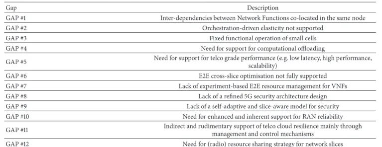
Table 1 provides a summary of gap analysis with respect to ongoing 5G system architecture design efforts in the industry and academia.
3. Enabling Innovations for 5G Services
In this section we detail some key identified enabling innova-tions for 5G services to address several gaps identified before. In particular, we present the design guidelines for (i) flexible cloudification of protocol stack, (ii) we present adaptive network slicing, inter-slice control and management, and (iii) we explore leveraging experiment- and implementation-driven modelling and optimisation to refine models on computational behaviour and derive the corresponding algo-rithms.
3.1. Cloud-Enabled Protocol Stack. In a cloud-enabled
archi-tecture, network nodes become general-purpose processors capable of running any network functions (NF), and NFs are virtualised, decomposed, and flexibly placed in different locations. This flexibility can be beneficial for many different services. For instance, a network slice providing an eMBB service may have most of its VNFs at a centralised location, while an URLLC one may want to exploit resources at the edge.
Existing concepts for the flexible allocation of NFs use a protocol stack that is not necessarily optimised for this purpose (especially for the RAN part). Indeed, “traditional” protocol stacks have been designed under the assumption that certain functions reside in the same (fixed) location and work close to optimality as long as such NFs are colocated in the same node. As a result of this, in the traditional protocol stack we typically have interdependencies between the NFs
Table 1: List of gaps identified from multiple sources.
Gap Description
GAP #1 Inter-dependencies between Network Functions co-located in the same node
GAP #2 Orchestration-driven elasticity not supported
GAP #3 Fixed functional operation of small cells
GAP #4 Need for support for computational offloading
GAP #5 Need for support for telco grade performance (e.g. low latency, high performance,
scalability)
GAP #6 E2E cross-slice optimisation not fully supported
GAP #7 Lack of experiment-based E2E resource management for VNFs
GAP #8 Lack of a refined 5G security architecture design
GAP #9 Lack of a self-adaptive and slice-aware model for security
GAP #10 Need for enhanced and inherent support for RAN reliability
GAP #11 Indirect and rudimentary support of telco cloud resilience mainly through
management and control mechanisms
GAP #12 Need for (radio) resource sharing strategy for network slices
colocated in the same node: while such interdependencies do not harm the performance as long as the NFs are close to each other, they limit the flexibility in placing these NFs in different nodes.
This may compromise the overall gains obtained from the flexible function allocation. To overcome this problem, one of the key innovations needed to fully exploit the proposed orchestration-driven architecture is the redesign of the protocol stack with the goal of leveraging the benefits of the flexible function decomposition and allocation, which we call the orchestration-enabled protocol stack. The aim is to relax and (as much as possible) remove the logical and temporal dependencies between NFs, with the goal of providing a higher flexibility in their placement. This results in a fundamental piece of innovation termed as network elasticity.
Elasticity of NFs involves the ability to scale the com-plexity of the NFs based on the available resources (i.e., processing power, memory, and storage): in case of a resource outage, NFs should adjust their operation to the available resources while minimising the resulting impact on network performance, thus providing a graceful degradation. As a result, we have NFs that are robust against “computational outages” if there are insufficient resources to perform the required tasks within the given time. This represents a new paradigm in the design of NFs: while traditional NFs have been designed to only fight the well-known “channel outages” concept, here we advocate for designing NFs that are also robust to the fluctuation of computational resources needed to accommodate the varying load of a network slice. In this way, the performance may degrade gracefully under com-putational outages, in contrast to traditional schemes where the performance degrades drastically in case of insufficient computational resources to decode all received data frames.
With a graceful degradation, several KPIs can be updated. Graceful degradation of VNF supports accommodating tran-sient huge spikes of traffic demand without disrupting service while more resources are activated. It also prevents abrupt
degradation of services when resources are missing due to temporary high demands. For capacity-limited deployments, cloud-aware network design improves the efficiency of net-work deployments (more users can be served using the same HW).
Next step in the same research path is considering the net-work elasticity in a multi-tenant environment. While offering isolation to network slices, it is possible to improve resource utilisation efficiency. However, serving multiple slices with different services and quality of service (QoS) requirements is a non-trivial task. To ensure achieving acceptable network performance, scaling of NFs for each network slices has to be done based on available computational resources, the slices’ SLA, and demands in addition to allocated radio resources [23].
3.2. Inter-Slice Control and Management. The network slice
awareness in 5G will strongly affect several key design requirements in different domains.
RAN Domain Aspects. One important area is the RAN design
and particularly the control plane (CP) design, where mul-tiple slices, with different optimisation targets, will require tailored access functions and functional placements to meet their target KPIs.
In slice-aware RAN, the CP can be categorised in the following groups of functionality based on the RAN Config-uration Modes (RCM) framework.
Intra-RCM RRM: for slice-specific resource management
and isolation among slices, utilising the same RAN is an open topic which is currently investigated. The conventional management of dedicated resources can be seen as intra-slice RRM, which can be tailored and optimised based on slice-specific KPIs.
Inter-RCM RRM/RRC: on top of Intra-RCM RRM,
Inter-RCM RRM/RRC can be defined as the set of RRM policies that allow for sharing/isolation of radio resources among slices or slice types to optimise the resource efficiency and
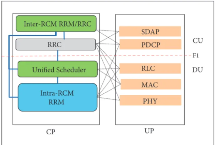
Intra-RCM RRM F1 PHY MAC RLC PDCP CP UP Inter-RCM RRM/RRC Unified Scheduler CU DU SDAP RRC
Exemplary Slice-aware CP Split for CU-DU HLS
Figure 1: Exemplary RAN functional deployment and interactions.
utilisation, by flexibly orthogonalising them in coarse time scales. Inter-RCM RRM can be defined as an “umbrella” functional block which dictates the RAN sharing and level of isolation/prioritisation among network slices or slice types. In this direction, an Inter-RCM RRM mechanism is pro-posed in [31], where slice-aware RAN clustering, scheduler dimensioning, and adaptive placement of intra-slice RRM functions are discussed in order to optimise performance in a dense heterogeneous RAN. Given the requirement of new access functions which can be tailored for different network slices, the distribution of RRM functionality in different nodes will be a key RAN design driver which can allow for multi-objective optimisation in a multi-layer dense RAN. The adaptive allocation of such functions is also envisioned as a key feature to cope with the dynamic changes in traffic load, slice requirements, and the availability of backhaul/access resources. To this end, one further inter-slice/RCM RRM functionality is proposed in [34] which performs traffic forecasting of different slices and allocates resources to slices in a proactive manner.
Figure 1 shows the possible placement of Inter-RCM and Intra-RCM RRM and Radio Resource Control (RRC) functionality. Depending on the placement the interface requirements might be different due to the time/resource granularity of the CP functionality and their possible inter-connections.
Core Domain Aspects. Another key area to realise flexible
end-to-end network slicing is core network design. The design paradigm within the core network has gradually shifted towards a functional service-based architecture (SBA) in line with industry consensus [10] where CP NFs are intercon-nected via a common bus to each other, termed as service-based interface (SBI). SBA is expected to have the advantage of short roll-out time for new network features, extensibility, modularity, reusability, and openness [35]. SBA allows the definition and instantiation of flexible E2E networks, which can be customised by network operators’ or vertical indus-tries’ requirements, in terms of performance, capabilities, isolation, etc. In other words, this allows the support of
network slices, i.e., independent logical networks, either sharing partly/entirely the infrastructure they are instantiated on or isolated and deployed over separate infrastructures.
5G devices will be able to access the network core and utilise supported services from a number of network slices. One key function, in this direction, is the network slice selection function (NSSF) as NF dedicated to selecting a proper network slice instance (NSI) for the 5G devices. There are several other NFs envisioned to customise network slices capabilities. For example, the Session Management Function (SMF) may allow the support of different UP protocol models, such as IPv4/IPv6 or Ethernet. The Policy Control Function (PCF) allows customising the policy framework on network slice basis. Finally, the Unified Data Management (UDM) function enables different authorisation, authen-tication, and subscription management mechanisms upon network slice tenant needs.
It should also be noted that, thanks to SBI, 3rd parties can also influence the network behaviour and extend and customise network slices capabilities via the inclusion in the system of proprietary non-standard Application Functions (AFs) or via exposing theirs services to other NFs, e.g., via Network Exposure Function (NEF).
Context-Awareness, Sharing, and Optimisation. A separate
distinguishing feature of next generation networks is sup-porting network and user context as a means to further optimise network and cross-slice operations via support-ing network analytics capability embedded in the general framework. Context-awareness is required in order to have flexible and dynamic function deployment as well as unified resource allocation and optimisation decisions between slices and users. This can be achieved by having shareable data storage mechanisms such as databases deployed as VNFs along with mechanisms to publish/subscribe to the shared context information.
Such functionality has currently been envisioned within the core via the Network Data Analytics Function (NWDAF). NWDAF provides the network core with the ability to collect and analyse per slice aggregated data and to aid network optimisation via interaction with other NFs (e.g., NSSF or PCF).
From RAN and terminal perspective, user devices are natural data collection points to gather above analytics within the network. As users can simultaneously connect to or switch across different slices (e.g., in case of mobility), they can have more prominent role for data preparation for the network to cleanse/normalise the information and to identify earlier anomalies compared to the past intra-slice and/or cross-slice information they have gathered. This opens the horizon for another level of context-awareness within the next generation networks.
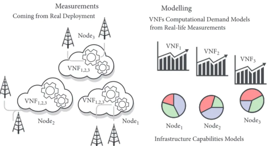
3.3. Experiment-Driven Optimisation. In a fully softwarised
network architecture, the optimisation of the orchestration of the whole network needs to consider the computational behaviour of nodes and NFs. Orchestrating NFs imposes some constraints, especially at the edge of the network where it is likely that resources are limited or very expensive.
Measurements Modelling Design Coming from Real Deployment VNFs Computational Demand Models
from Real-life Measurements
Algorithmic Design based on VNF Models
Orchestration Algorithm Design
Infrastructure Capabilities Models
6.&1 6.&1,2,3 6.&1,2,3 6.&1,2,3 6.&2 6.&3 .I>?3 .I>?3 .I>?2 .I>?2 .I>? 1 .I>?1
Figure 2: Experiment-driven modelling and optimisation.
To perform the placement of NFs based on computational resources, traditional approaches assume that NFs (and cloud locations) consume (and offer) a fixed amount of resources (i.e., processing power, memory, and storage) [36, 37]. However, this model is very coarse and clearly insufficient to understand the performance of a real environment in which the computational load fluctuates significantly over time. Much more accurate results can be achieved if accurate models of the computational behaviour (of both VNFs and NFVI) exist.
Designing algorithms to carefully allocate VNFs to the nodes in the network involves the following challenges: (i) characterising the VNF’s temporal behaviour by modelling the occurrence of peaks of resource consumption and periods of lower load, (ii) evaluating the (non-negligible) overhead incurred by computational resources used to run system management software, and (iii) assessing the impact of the communication environment as well as the logical dependen-cies between NFs, which introduce statistical dependendependen-cies in the computational demands of such functions.
It is worth noting that the implementation techniques (i.e., programming approaches) used in realisation of VNFs influence the behaviour VNFs. Hence, these challenges nec-essarily need to rely on experiments that evaluate the real computational behaviour of the different components. This can be accomplished following the methodology depicted in Figure 2. First, measurements need to be performed in real deployments of VNFs in fully operational networks. Then, their behaviour can be modelled to clearly understand both the VNF resource consumption and the infrastructure capabilities. Finally, this input can be used to design enhanced orchestration algorithms.
Via having different functionality virtualised, the cloud infrastructure providers have to develop an experimental procedure to meet the QoS requirements of each VNF optimally. Scaling and elasticity decisions (either vertical or horizontal) cannot be made without having a practi-cal experimental optimisation approach. Experiment-driven optimisation is enabled through measurement campaigns (i.e., a monitoring process). The measurements from these campaigns feed a modelling procedure, which models the
VNF behaviour regarding their computational, storage, and networking resource demands. The resulting models may facilitate the overall resource management of the cloud infras-tructure. In [38], the experimental modelling of physical layer is presented.
Algorithms and functions that apply upon the 5G pro-tocol stack can improve their performance by exploiting experiment-driven insights and, thus, taking more intelligent decisions. In this context, the experiment-driven modelling and optimisation is a key innovation enabler filling the current gap on experiment-based E2E resource management for VNFs. This also brings a new paradigm in network management and orchestration by feeding with experiment-based inputs.
4. Flexible Architecture Design
Following the gaps analysis in the literature and key enabling innovations to realise the 5G services, we have designed a flexible architecture enabling dynamic network slicing as part of a 5GPPP Phase 2 project, 5G-MoNArch [14], to meet 5G systems objectives. The reference architecture model proposed here extends the reference architectures proposed by 3GPP, 5GPPP Phase 1 projects, and ETSI by building on these architectures while addressing several gaps as identified in Section 2.
4.1. Overall Design Principles. The proposed overall
func-tional network architecture consists of four different layers, identified as network layer, controller layer, management and orchestration layer, and service layer as shown in Figure 3. A key contribution of this paper is the definition of the role of each layer, the relationship between layers, and the identification of the required network functions within each of the layers.
Thenetwork layercomprises the VNFs and physical NFs
(PNFs) of both control plane (i.e., cVNF, cPNF) and user plane (i.e., uVNF, uPNF). NFs can include, for example, 3GPP Rel. 15 CP functions (PCF, SMF, UDM, RRC, etc.) and user plane (UP) functions (i.e., UPF) or novel NFs developed here, e.g., for resource elasticity, resilience, and
Ne tw o rk la ye r M anagemen t & Or chestr at io n la ye r E2E S er v ic e M anagemen t & Or chestr ati o n (M&O) Se rvi ce la ye r Decision Policies
Applications & Services
Intra-Slice NFs (INFs)
uPNF uVNF uVNF
uPNF
uVNF Cross-Slice NFs (XNFs)
uPNF uVNF uPNF
cVNF cPNF cPNF cVNF cVNF cVNF Cross-slice functions Intra-slice functions BSS 3GPP N etwo rk M anagemen t NSMF EM EM EM En te rp ris e N etwo rk Mg m t SNMP Manager 802.1ag CFM PLC/ SCADA CSMF DM DM NM T ransp o rt N etwo rk M anagemen t Mgmt Fct #1 Mgmt Fct #n Cross-slice M&O Cross-domain M&O NSS I 2 NSS I 3 NSS I 4 NSS I 1 uPNF cVNF C o ntrol ler la ye
r ISC Control Applications
ISC NBI NBI SoBI SoBI XSC Control Applications XSC NSS I 4 V ir tualisa ti o n MAN O VIM VMIMF CIMF VNF Manager VMI CI NFVO Itf-X MOLI 5G-MoNArch NFs Baseline Architecture cVNF
Figure 3: Proposed overall functional architecture [14].
security. Generally, the network layer can comprise different CP/UP architectures; i.e., also a 4G mobile network with EUTRAN and EPC functions could constitute an instance of the network layer. Interfaces towards the M&O layer are provided via theItf-Xreference point. It is an evolution of the 3GPPItf-Sinterface between element manager (EM) and network element (NE), e.g., eNB, and facilitates domain-specific fault, configuration, accounting, performance, and security (FCAPS) management as well as domain-agnostic lifecycle management (LCM) procedures. For associating a UE to the correct NSI, the network layer uses the Single Network Slice Selection Assistance Information (S-NSSAI), which is provided by the UE. Moreover, the CN part of the CP in the network layer is realised as SBA [10]. Further details of the network layer are depicted in Section 4.2.
The controller layer realises the software-defined
net-working concepts [39], extends them to mobile networks, and therefore accommodates two controller types:
(1) the coss-slice controller (XSC), e.g., a RAN con-troller for the control of cross-slice network functions (XNFs) that are shared by multiple network slices, (2) the intra-slice controller (ISC), e.g., a CN controller
for intra-slice network function (INFs) within a ded-icated CN network slice subnet instance (CN-NSSI). These controllers expose a northbound interface (NBI) towards control applications and a southbound interface (SoBI) towards VNFs and PNFs in the network layer.
Interfaces towards the M&O layer are provided via theMOLI
reference point. The controller layer facilitates the concept of
mobile network programmability. Generally, software-defined
networking (SDN) splits between logic and agent for any functionality in the network. This means that the NFs are split into the decision logic hosted in a control application and the actual NF in the network layer (usually a uPNF or uVNF) that executes the decision. In other words, for the given uVNF or uPNF, the according cPNF or cVNF would disappear. The controller resides “between” application and NF and abstracts from specific technologies and implementations realised by the NF, thus decoupling the control application from the con-trolled NF (cf. Figure 3). If no such split between control logic and agent is applied, i.e., the cPNFs and cVNFs incorporate both, the controller layer disappears. In this sense, it is an optional layer of our proposed architecture. Further details of the controller layer are described in Section 4.3.
The management and orchestration layer is composed
of the M&O functions from different network, technology, and administration domains: 3GPP public mobile network management, ETSI NFV management and orchestration (MANO) [40], ETSI multi-access edge computing functions [41], management functions of transport networks (TNs), and private enterprise networks. Further, the M&O layer comprises the end-to-end M&O sublayer hosting the Net-work Slice Management Function (NSMF) and Communica-tion Service Management FuncCommunica-tion (CSMF) that manage net-work slices and communications services, respectively, across
multiple management and orchestration domains in a seam-less manner. In the so-calledvirtualisation MANOdomain, the ETSI NFV MANO architecture for LCM of virtual machines (VMs) is extended towards LCM of virtualisation containers (e.g., Docker). Therefore, it comprises, besides the ETSI NFV components, corresponding functions for LCM of containers. Therefore, the Virtualised Network Function Manager (VNFM) has according components for virtual machine infrastructure (VMI) and container infrastructure (CI). Similarly, the Virtualised Infrastructure Manager (VIM) contains a VMI management function (VMIMF) and a CI management function (CIMF). NFV orchestrator (NFVO) provides the dispatching functionality. Further, the layer accommodates 3GPP network management function, such as element and domain managers (EM and DM) and network management (NM) functions. Such functions would also implement ETSI NFV MANO reference points to the VNFM and the NFVO. The CSMF transforms consumer-facing service descriptions into resource-facing service descriptions (and vice versa) and therefore works as an intermediary function between the service layer and the NSMF. The NSMF splits service requirements as received from CSMF and coordinates (negotiates) with multiple management domains for E2E network slice deployment and operation. As a major architecture novelty, NSMF further incorporates a cross-slice M&O function for inter-slice management (e.g., common context between different slices/tenants, inter-slice resource brokering for cross-slice resource allocation, particularly in the case of shared NFs, etc.). In contrast, the cross-domain M&O function works on strictly intra-slice level, but across multiple network and technology domains. The M&O layer performs the management tasks on network slice instances (NSI), which are uniquely identified by an NSI identifier. An NSI may be further associated with one or more Network Slice Subnet Instances (NSSI). Further details of the M&O layer are described in Section 4.4.
The service layer comprises Business Support Systems
(BSS), business-level policy, and decision functions and further applications and services operated by a tenant or other external entities. These functions of the service layer interact with the M&O layer via the CSMF, as described above.
Figure 3 implicitly illustrates three fundamental design
aspectsthat we have followed in our proposed architecture:
(1)Support for E2E network slicing: the architecture
allows for combining different options of slicing support across M&O and network layers for each slice instance. The first supported option includes slice-specific functions; i.e., each slice may incorporate dedicated and possibly customised functions that are not shared with others. The second option includes the possibility of operating functions (or function instances) that are shared by multiple slices and have the capability to address requirements from multiple slices in parallel. Figure 3 depicts this split into common or so-called inter-slice functions and dedicated (intra-slice) functions. This split can be maintained in the M&O layer, the network layer, and the optional controller layer; i.e., dedicated NFs
may be controlled and managed by the tenant’s own instance of ISC and M&O layer functions. Shared functions are usually operated by the mobile net-work operator (MNO) or the communication service provider. The MNO (together with potential third-party infrastructure providers) is also in charge of managing the infrastructure. The policies regarding the utilisation of shared functions, particularly the resource allocation to active slices, are determined by the cross-slice M&O function, and communicated towards the respective network layer functions for further enforcement. Finally, the third option is to not only have slice-dedicated NFs but also addi-tionally assign the associated infrastructure hardware resources (HW), including spectrum, exclusively to a single slice. The slice-specific functions and shared functions in one logical slice are bound together by the network slice identifier at the network layer. (2)SBA: the service-based interaction between core
net-work CP NFs provides a set of features and associated advantages. Among others, NFs can be realised in a stateless manner since such state-related data (e.g., session data) are shared via a message bus, sometimes referred to as data bus. SBA facilitates the design of modularised NFs, uniform interaction procedures between NFs (e.g., NFs can offer their functionality as a service to other NFs), unified authentication framework between NFs, and concurrent access to services.
(3)Split of control and user plane: we apply a consistent
split of control plane and user plane throughout all network domains, including RAN, CN, and TN. Among others, this allows for hosting associated CP and UP NFs in different locations and also facilitates aggregating CP and UP NFs differently. The split further allows independent scalability and evolution of NFs.
4.2. Network Layer. In this section, the highlights of the CN,
also referred to as 5G core network (5GC) and RAN, are outlined.
4.2.1. Core Network. The key technological components of
5GC are architecture modularisation, CP-UP separation, and service-based interface (SBI). These are reflected in the SBA (crystallised in 3GPP Release 15 specifications [10]) where the CP NFs are interconnected via the SBI. Each NF, if authorised, can access the services provided by other NFs via the exposed SBI. 5GC includes new NFs that enable the principles of SBA. Namely, NEF is an NF included in the 5GC which allows each NF to expose its capability to other NFs and the Network Repository Function (NRF) is an NF included in the 5GC allowing each NF to discover which instance of another NF can be accessed to receive a required service. A separate dis-tinguishing feature of 5GC, compared to previous generation networks, is network analytics capability embedded in the general framework, via the definition of NWDAF. In short, as per 3GPP Release 15, NWDAF provides 5GC with the ability
UE (R)AN UPF AF AMF SMF PCF UDM DN N6 NRF NEF N3 N2 N1 N4 AUSF Nausf Namf Nsmf Npcf Nnrf
Nnef Nudm Naf
NSSF Nnssf AF NWDAF Nnwdaf Naf ISCF
Figure 4: 5GC Architecture and the proposed functional enhancements. The impacted NFs are marked where ISCF is a new NF envisioned to be part of the AMF functionality.
to collect and analyse per slice aggregated data and to aid network optimisation via interaction with PCF and NSSF. Albeit included in 3GPP Release 15 specification, NWDAF description and capabilities are extremely rudimental. In addition, the access network (AN) CP is connected to the Access and Mobility Management Function (AMF) of 5GC in case of 3GPP access and is connected to the Non-3GPP Interworking Function (N3IWF) in case of non-3GPP access. Compared to the traditional reference-point-based network architecture design, SBA has the advantage of short roll-out time for new network features, extensibility, modularity, reusability, and openness [35].
Our proposed architecture, which is based on SBA prin-ciples, allows the definition and instantiation of flexible E2E networks, which can be customised by network operators’ or vertical industries’ requirements, in terms of performance, capabilities, isolation, etc. In other words, 5GC reference architecture allows the support of network slices, i.e., inde-pendent logical networks, either sharing partly/entirely the infrastructure they are instantiated on, or isolated and deployed over separate infrastructures. 5G devices will be able to access 5GC and requiring services from a number of supported network slices. It should also be noted that, thanks to SBI, the reference architecture also provides 3rd parties with the possibility of influencing the network behaviour and extending and customising network slices capabilities via the inclusion in the system of proprietary non-standard AFs.
Although the foundations for 5GC have been successfully established, the general framework still appears to be not entirely mature, and it seems to be still susceptible to significant technical and conceptual enhancements. Some key examples of issues still offering a large number of design options and room for further improvements are as follows:
(i) The instantiation and selection of NFs for different slices in the infrastructure
(ii) The specific functional customisation of NFs to ad-dress requirements of specific use cases
(iii) The functional interaction among different network slices
On this basis, the 5GC architecture along with the envisioned extensions and impacted NFs is shown in Figure 4. These modifications are listed in the following.
(i) To enable inter-slice context-aware optimisation: enhancements of NWDAF to collect and provide per slice/cross-slice feedback information to the NFs and to collect information from M&O layer and maybe also provide feedback to M&O layer per slice/cross-slice and enhancements of NWDAF, NFs, and M&O layer to coordinate the execution of changes in the 5G system based on the feedback provided by NWDAF in case of the CP / M&O layer joint optimisation cases. (ii) To improve slice selection and control: enhancement
of NWDAF and/or NSSF to collect/process terminal-driven analytics.
(iii) To enable inter-slice coordination: introduction of inter-slice coordination function (ISCF) within AMF, which provides per service traffic flow binding and distributes the service traffic flow binding informa-tion to other NFs.
(iv) Enhancement of PCF to treat per service correlated QoS profiles considering above-mentioned inter-slice coordination.
4.2.2. Radio Access Network. From the specification
perspec-tive, 3GPP Release 15 for next generation-RAN (NG-RAN) is frozen by the time of the submission of this paper (a so-called late drop of Release 15, which includes further architecture options, is planned to be frozen by the end of 2018). This specification comprises slicing awareness in RAN via NSSAI including one or more S-NSSAIs, which allow for uniquely identifying a network slice [9]. While the fundamental slicing support is achieved by Release 15, e.g., granularity of slice awareness and network slice selection, various enhancements and optimisation can be considered for future releases. Such enhancements may imply, for example, specification-relevant signalling changes and implementation-dependent algorithms, e.g., related to resource management (RM)
gNB gNB 5G Core Network (5GC) AMF UPF Xn NG-Uu N2 N3 N2 N3 CU DU DU CU DU DU F1 F1 … NBI SoBI SoBI NG-Uu UE XSC ISC Controller Layer APP APPn
Figure 5: High-level RAN architecture.
between slices. Accordingly, the foreseen enhancements are mapped to the specified baseline Release 15 architecture, as shown in Figure 5. It is worth noting that the proposed controller layer is covered in Section 4.3.
In principle, network slicing offers additional degree of flexibility, where NFs can be tailored according to the requirements of slice tenants. To this end, it can be expected that different tenants can have vastly changing needs which can be categorised into three levels, as illustrated in Figure 6 [15]. On one end, some of the slice tenants may only require a performance differentiation, e.g., in terms of QoS requirements, such as latency and data rate, which can be extended by further SLA requirements, such as number of connections for a given time and location. On the other end, slice tenants can require a self-operation of the network services (NSs), such as NF deployment, monitoring, and fault management with dedicated network deployment. In addition, differentiation can be partially on a functional level, where customised NFs can be introduced by the slice tenants, such as customised security and isolation.
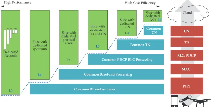
Accordingly, slice tenant requirements can be supported by different network slicing realisation variants as depicted in Figure 7 [14]:
(i) In the first variant (L0), an independent operation can be realised by a dedicated network, e.g., in case of public safety or railway communications.
(ii) In the second variant (L1), the slices may be allocated with dedicated spectrum, where multiple slices can share the baseband processing and antennas. (iii) A third possible realisation variant (L2) can be to
share spectrum dynamically among different network slices, making the spectrum allocation can on a time slot basis or on a semipersistent way.
(iv) A fourth variant (L3) is to share the whole RAN protocol stack by slices where SLA differentiation can
Independent Operation Functional Differentiation Performance Differentiation
Figure 6: High-level classification of the slice tenant requirements [15].
be performed with QoS enforcement. In particular, in line with the latest 5G specification, for an NSI one or more Protocol Data Unit (PDU) sessions can be established, where a PDU session belongs to one and only one specific NSI [10]. Further, RAN maps packets belonging to different PDU sessions to different data radio bearers (DRBs), where within a PDU session there can be one or more QoS flows [9]. On this basis, the RAN treatment of different network slices can be in terms of RRM schemes performed based on the QoS profiles of QoS flows mapped onto the respective DRBs, where QoS profiles can include performance characteristics, e.g., packet delay budget and packet error rate, and allocation and retention priority (ARP).
Slice with dedicated QoS Dedicated Network Slice with dedicated spectrum Slice with dedicated protocol stack Slice with dedicated TN and CN
Common RF and Antenna
Common Baseband Processing
PHY RLC, PDCP TN CN Common PDCP RLC Processing Common TN Slice with dedicated CN Common CN MAC
High Performance High Cost Efficiency
L0 L1 L2 L3 L4 L5 L1, L2, L3, L4, L5 Cloud
Figure 7: High-level slicing realisation variants that can affect intra-slice and cross-slice control functions.
(v) The last two variants do not only share the RAN among the various slices but also the transport net-work (TN) in L4 and both the TN and CN in L5. The choice towards the slicing realisation variants described above (involving the design of the slice-tailored NFs at different levels) depends on the needs of the slice tenants and how these needs can be realised on the RAN side. Thus, it is expected that different realisation variants or combinations thereof (e.g., partly shared core NFs and partly slice-specific core NFs) can coexist. Yet, it seems that the variants L0, L1, and L4 may be realised first in 5G deployments. In case high isolation is required (variants L0 and L1 in Figure 7), all RAN protocol stack functions can be tailored according to the slice requirements. In such cases, for instance, each slice can run its tailored dynamic scheduler as an intra-slice control function. In realisation variants, e.g., L4 in Figure 7, where the whole RAN protocol stack is shared by different network slices, the control functions are of the cross-slice form. Under the light of the above discussion, part of the cross-slice control functions, e.g., slice-aware RRM, can be implemented as intra-slice control functions when a high-isolation realisation variant is considered. It is worth reemphasising that even though the whole RAN protocol stack is shared by different network slices, slice-specific performance requirements can be fulfilled with appropriate QoS enforcement, as discussed under the L4 variant above.
4.3. Controller Layer. Following the network softwarisation
trends, due to the extensive application of the software-defined networking concept to the entire NFs in a mobile network, the control and data layer will necessarily be split by the controllers. Controllers split the functionality between the application logic (i.e., the intelligence that runs in the
applications) and theagentsrunning in the NFs. Therefore, our proposed control and data layer architecture makes use of the controller.
Control plane applications are the centralised controller layer that comprises an ecosystem of applications controlling the underlying NFs (dedicated or shared), exploiting the advantages of the SDN approach.
The separation of control and execution parts of a net-work function implies that both parts are connected through an appropriate interface that is able to carry
(i) commands from the control part to the execution part,
(ii) acknowledgments to these commands back from the execution part to the control part,
(iii) indications, measurements, and status reports from the execution part to the control part.
This kind of interface is shown as Southbound Interfaces (SoBIs) in Figures 3 and 5.
As the network function specifics change substantially from one another, it is near at hand that their SoBIs will require substantially different capabilities. Alternatively, all these interfaces could be bundled in a single southbound interface for the ISC/XSC. However, this SoBIs might become very feature-rich and complex.
Some network functions exist for which possibilities to split control and execution parts have been discussed already in literature and for which suitable interfaces have been described, such as the separation between RRC from lower layer RAN protocols through the NBAP protocol, OpenFlow powered mobility management protocols, and, in general, the management of the transport network.
Having a unified controller point for the full network (at least from the logical perspective) will be a fundamental
E2E Service Management & Orchestration CSMF
NSMF
Cross-Domain M&O Cross-Slice M&O
NSSMF
S. Allocation S. Configuration S. Activation
S. S. Allocation S. S. Configuration S. S. Activation S. Alarm S. S. Alarm Requirements Translation Requirements Update Service. Allocation Service.
Activation Service. Analytics
S. Blueprint NSSI Decomposition
NSD Creation
Cross Slice Requirements verification
Cross Subnet Requirements verification
Big Data Module NFV MANO NFVO (CS & VMs) VNF Manager VMI CI VIM VMIM CIMF S. Performance Monitoring SS. Performance Monitoring Monitoring Data S. SOMO S. S. SOMO CROSS S. SOMO S. Measurement Job S. S. Measurement Job
Figure 8: The proposed E2E service management and orchestration layer.
building block for 5G Networks; otherwise, the management and orchestration of a diverse and extensive ecosystem of network slices, such as the one currently envisioned, will be too complex to manage.
Since SDN controllers initially developed in the scope of transport networks, the implementation of such a solution in mobile networks (e.g., RAN) requires further optimisa-tion of their funcoptimisa-tionality and performance using modern software engineering methodologies. There are some studies focusing on the scalability of wired SDN [42, 43], but it is difficult in the wireless scenarios. As the size of a network enlarges, more packets are sent to the controller. There is no doubt that the controller can hardly handle all these incoming requests. Simply improving the performance of a sole centralised controller, without altering the design from the architectural perspective, cannot scale well with the wide-ranging dense network dimensions. Therefore, controllers for mobile networks might consist of multiple controllers physically distributed in the system. These controllers will not conflict with the “logically centralised” principle as they com-municate and cooperate with each other efficiently. This is one of the important considerations in our proposed architecture to have a controller framework that is distributed, scalable, and resilient to satisfy the stringent latency requirements of mobile networks.
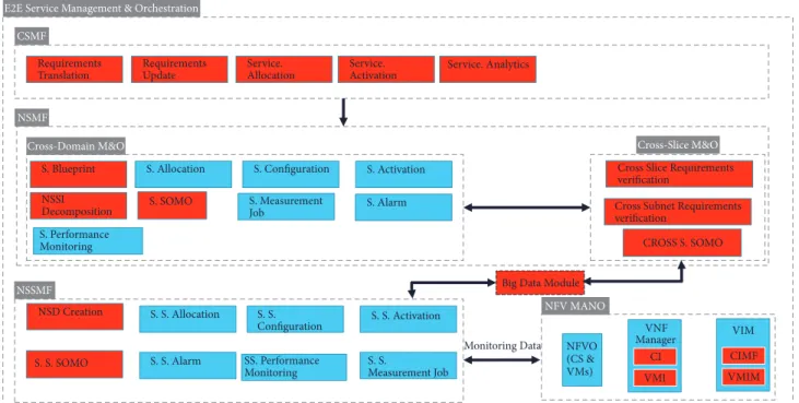
4.4. Management and Orchestration Layer. E2E
manage-ment and orchestration is performed at different levels in a coordinated manner. These levels are service, network configuration, virtualisation, and transport. Our proposed management and orchestration layer takes care of this job, interworking with control layer and network layer, to deploy the required network functions and to configure the
appropriate interconnections according to the service and network requirements.
The deployment and management of a network slice is performed by the management and orchestration layer to fill the request of a customer for a communication service. Two models are foreseen in this framework: network slices as network operator internals and network slice as a Service (NSaaS). In the first case, network slices are used by the network operator to fulfill the request to provide a commu-nication service and are optimised and operated accordingly. In the second case, the network slice can be offered by a network operator to a communication service provider with a set of management functions. The communication service provider uses and manages the network slice building up his communication service on top of it.
Management and orchestration layer has to be aligned with 3GPP specifications that foresee a management sys-tem that coordinates network and slice management and orchestration. Our current architecture explicitly takes into account the interaction with the 3GPP Management Entities dedicated to network management and configuration (see Figure 8) and enhances the 3GPP 5G Management System manages NSI using two new functions:
(i) The NSMF is responsible for management and or-chestration of NSI and derives network slice sub-net related requirements from sub-network slice related requirements. It communicates with the Network Slice Subnet Management Function (NSSMF) and Communication Service Management Function. (ii) The NSSMF is responsible for management and
Modification Activation Creation Preparation Network environment preparation Design boarding
On-Commissioning Operation Decommissioning
Termination Supervision Reporting
Lifecycle of a Network Slice Instance
De-activation
Figure 9: Management aspects of network slice instance [33].
The Network Slice Management and Orchestration is also based on ETSI NFV MANO orchestration framework [44], which introduces the concept of network service (NS) as a set of NFs connected according to one or more forwarding graphs. This framework uses the Network Service Descriptor (NSD) as the templates to manage the lifecycle of a NS and to describe the requirements of VNF, respectively [45]. In addition, in ETSI NFV MANO, the VIM is responsible for control and management of NFVI compute, storage, and network resources; the VNF Manager uses the VNF Descriptor in charge of the LCM of VNF instances, and the NFVO is responsible for the orchestration of NFVI resources and lifecycle management of NS.
In the E2E service management and orchestration layer, the requirements of a new service are translated into network requirements by the CSMF. The obtained network require-ments are forwarded to the NSMF, which addresses the management of each slice (Cross-Domain M&O) and the orchestration of different slices (Cross-slice M&O).
To fill the identified gaps in the current architecture (see Section 2), the management and orchestration layer has to identify the VNFs/PNFs to satisfy the service require-ments and their relationships (i.e., the forwarding graph of the service); define the configuration and policies (e.g., for elasticity) to fulfill the required service and SLA and then setup the most appropriate network slice template (for network management) and Network Service Descriptor (for VNF deployment); and identify the network KPI associated with the requested SLA and then finalise the deployment and activation of the Network Slice Instance associated with the required service. Therefore, the management and orches-tration layer activates the Performance Management (PM) and Fault Management (FM) functions, which continuously monitors the system KPI and triggers necessary orchestration function to fulfill service changes requests or to meet the SLA. Finally, the management and orchestration layer is in charge of exposing PM and FM data to the customer (if requested).
According to [46] the lifecycle of a network slice is comprised of the four following phases as also shown in Figure 9:
(i) preparation; (ii) commissioning; (iii) operation; (iv) decommissioning.
The preparation phase includes the design of the network slice template, the on-boarding, the evaluation of the network slice requirements, the preparing the network environment, and other necessary function necessary before the creation of an NSI. From an NFV perspective the role of NFVO in the preparation phase is to ensure the resource requirements for a Network Slice Template (NST). NFVO contains the NSDs that have been previously on-boarded and that can be used to create new NSTs that are created and verified in the preparation phase. The NSDs can be updated and created from the beginning if required if a new NST is necessary.
The NSI is created during the the commissioning phase
involving the allocation and configuration of network slice resources required to satisfy the network slice requirements and then the creation of the NSI. During the commissioning phase the NFV MANO functions are only involved in the network slice configuration if parameters related to virtual-isation are required for any VNF instance and can be called in the network slice activation step. During the activation the NSMF or the NSSMF functions can activate VNF by means of
Update NSsent towards NFVO. This operation could include
adding, removing, or modifying VNF instances in the NS instance.
The operation phase comprises the activation, supervi-sion, performance reporting, modification, and deactivation of an NSI. The activation makes the NSI active and ready to support communication services. The modification can include the creation or modification of NSI constituents of characteristics (e.g., topology). The NSI modification can be triggered by new requirements or as a result of super-vision/reporting function. The deactivation makes the NSI inactive and stops providing communication services. Dur-ing the operation phase NFV MANO is responsible for per-formance management, fault management that could affect a VNF's functioning, and lifecycle of virtualised resources. This could include for example scaling of NS.
Finally, in the decommissioning phase the non-shared constituents are depleted and the NSI specific configuration are removed from the shared constituents. After the decom-missioning phase, the NSI is terminated.
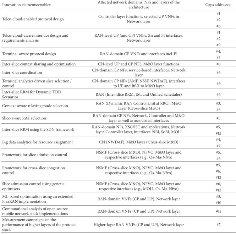
Table 2 summarises how captured enabling innovations (as covered by Section 3) address the identified gaps (in Section 2) and what are the architectural impacts (as covered in Section 4) per innovation concept.
Table 2: Mapping enabling innovations /architectural impacts to identified gaps.
Innovation elements/enabler Affected network domains, NFs and layers of the
architecture Gaps addressed
Telco-cloud-enabled protocol design Controller layer functions, selected UP VNFs inNetwork layer
#1 #2 #8 Telco-cloud-aware interface design and
requirements analysis
RAN-level UP (and CP) VNFs, Xn and F1 interfaces, Network layer
#1 #2 #9
Terminal-aware protocol design RAN-domain CP VNFs and interfaces incl. F1 #4,
#5 Inter-slice context sharing and optimisation CN-level UP and CP NFS, M&O layer functions #6 Inter-slice coordination CN-domain CP NFs, service-based interfaces, Network
layer #6
Terminal analytics driven slice selection / control
CN-domain CP NFs (AMF, NSSF, NWDAF), interfaces
to UE and Itf-X to M&O layer #6
Inter-slice RRM for Dynamic TDD
Scenarios RAN (Inter-slice RRM, IM, and Unified Scheduler) #6
Context-aware relaying mode selection RAN (Dynamic RAN Control Unit at RRC), M&OLayer (Cross-slice M&O) #3, #6 Slice-aware RAT selection RAN-domain CP NFs, Network, Controller and M&Olayer as well as associated interfaces #5
Inter-slice RRM using the SDN framework RAN-domain NFs, XSC/ISC and applications, Network layer, Controller layer, interfaces: NBI, SoBI, MOLI
#5, #12 Big data analytics for resource assignment CN (NWDAF), M&O layer (Cross-slice M&O) #4, #7 Framework for slice admission control NSMF (Cross-slice M&O), NFVO, M&O layer andrespective interfaces (e.g., Os-Ma-Nfvo) #5, #6 Framework for cross-slice congestion
control
NSMF (Cross-slice M&O), NFVO, M&O layer and respective interfaces (e.g., Os-Ma-Nfvo)
#5, #6, #12 Slice admission control using genetic
optimisers
NSMF (Cross-slice M&O), NFVO, M&O layer and respective interfaces (e.g., MOLI, Os-Ma-Nfvo)
#6, #12 ML-based optimisation using an extended
FlexRAN implementation RAN-domain VNFs (CP and UP), Network layer
#3, #10 Computational analysis of open source
mobile network stack implementations RAN-domain VNFs (CP and UP), Network layer #11
Measurement campaigns on the
performance of higher layers of the protocol stack
Higher-layer RAN VNFs (CP and UP), Network layer #7
5. Evaluation Studies and Analyses on Selected
Key Innovation Concepts
In this section, we present some key findings on innova-tion concepts enabling our proposed flexible, adaptable and programmable network architecture, reflecting how some identified gaps are addressed.
5.1. Telco Cloud Resilience. High resilience of the 5G mobile
network (cf. Gap #11) is tightly coupled with high resilience of the telco cloud as one of its integral components. One approach for improving the resilience is applying redundancy
in telco cloud deployment. Increased redundancy allows shorter failure recovery time and thus improves overall network availability. However, the increased redundancy also comes with increased costs and operational complexity. In general, a number N of components is backed up with a certain number M of additional components, forming the
N+M redundancy approach. There are different modes in which N components are interacting with M redundant components [47, 48].
Active-standby scheme assumes that one telco cloud
instance (e.g., VM, container) is processing the load, i.e., being active instance, whereas an additional instance is
prepared to take over the processing from active instance, once it fails. The procedure of taking over the processing load may incur a considerable delay. Such delay depends mainly on the level of readiness of the standby instance to take over the processing load
Load sharing scheme allows sharing of processing load
among instances. This scheme follows theN+Mredundancy approach, where onlyNinstances would be needed to handle the peak processing load, but additionalMinstances are used in parallel; thus the processing load is distributed among
N+Minstances. This redundancy scheme is mainly suitable for processing the tasks without major interdependencies.
Full redundancy (active-active mode) is an approach
where the active and redundant instance simultaneously perform the same processing task, where the final results of processing are compared, and faults may be identified. This approach is suitable mainly for cases with extreme availability requirements.
The resulting availability of the telco cloud depends on the availability of the single instance, type of redundancy scheme, and the level of redundancy applied. In order to select the most appropriate scheme for particular context in which the telco cloud is applied, it is beneficial to take the following inputs into account, among them (a) information regarding the required availability level of the telco cloud, given the required end-to-end availability of the service/slice, e.g., 99.99 % or 99.999 %, (b) type of network functions (NFs) deployed on the telco cloud with respect to processing state, i.e., statefull or stateless NF, and (c) dependencies among NFs and their processing tasks for validating the applicability of parallel processing.
Due to its cost efficiency the load sharing redundancy scheme usually is the most reasonable approach for the cases where the processing tasks can be executed largely in parallel. Furthermore, the resulting availability that can be achieved by load sharing scheme depends on the current load in the network. For example, in anN+Mload sharing scheme, in the case of lower load, i.e., onlyN-Pinstances are needed to handle the total load, the resulting redundancy scheme would be (N-P, M+P) which significantly increases the overall availability of the network. Figure 10, which is based on [48], illustrates the results of analytical analysis performed for the load sharing redundancy scheme where the following inputs are used:N=5,M=2,P=2, for different assumptions on availability of a single component. Additionally, Figure 10 shows the comparison between the load sharing approach and genericN+Mredundancy scheme without load sharing. Such generic redundancy scheme provides better results in terms of overall availability, at the cost of more resource usage and no flexibility with respect to the traffic load.
5.2. Inter-Slice Control and Management. Here, we
intro-duce the notion of network slicing in 5G TDD networks, considering a multi-service environment with asymmetric traffic conditions. Network slices are formed on-demand with the allocated resources being dynamically adjusted with the objective to enhance the resource utilisation efficiency. Each network slice is customised to accommodate distinct service types by allowing each tenant to adopt a different
Availability of a single component 0,970 0,975 0,980 0,985 0,990 0,995 1,000 Resul tin g co m p o u nd a va ila b ili ty 0,88 0,92 0,96 1,00 N+M redundancy scheme (N=5, M=2) N+M load sharing (N=5, M=2) N+M load sharing (N=3, M=4)
Figure 10: Overall availability of the network given different redundancy schemes and assumptions on availability of a single component.
TDD frame enabling a distinct UL/DL ratio, which can be reconfigured independently reducing the loss of multiplexing gain. One such TDD oriented network slicing framework is analysed in [49] considering an SDN-based architecture that enables multi-service and multi-tenancy support. However, the allocated slices have a fixed resource size for the entire duration of the service request, occupying only specific isolated subcarriers.
This study builds on top of this slicing framework con-sidering more dynamic slice allocations for dynamic radio topologies, addressing identified Gap #6 (E2E cross-slice optimisation), where slice resources can be adjusted during the time of a session request, introducing the following planned contributions.
A graph-based solutions framework is adopted as in [50] to optimise slice performance while keeping the signalling overhead and complexity. Initially, we provide a constraint-based greedy algorithm, whereas we solve the second sub-problem by a novel bipartite graph-colouring based solution, which aims to perform adaptive frequency partitioning per time slots in a way that interference due to resource conflicts is avoided and at the same time resource utilisation efficiency remains in high level. Initially, a bipartite graph is translated to a line colouring graph, where each node is a combination of link and transmission time interval (TTI) (edge of the bipartite graph). The edge between two nodes in the line colouring graph appears only if a conflict exists at the receiving end of the bipartite graph, which is equivalent of having two or more links being assigned to the same TTI. The graph-colouring algorithm assigns a different colour to a node only in case of a conflict, which means that different subbands will be scheduled to avoid interference. Based on this algorithm, the output is a timetable where each link is
![Figure 3: Proposed overall functional architecture [14].](https://thumb-us.123doks.com/thumbv2/123dok_us/10175802.2919893/7.900.90.812.111.577/figure-proposed-overall-functional-architecture.webp)

![Figure 6: High-level classification of the slice tenant requirements [15].](https://thumb-us.123doks.com/thumbv2/123dok_us/10175802.2919893/10.900.219.684.109.422/figure-high-level-classification-slice-tenant-requirements.webp)
![Figure 9: Management aspects of network slice instance [33].](https://thumb-us.123doks.com/thumbv2/123dok_us/10175802.2919893/13.900.107.794.105.265/figure-management-aspects-network-slice-instance.webp)