Full Length Article
Bat algorithm optimized fuzzy PD based speed controller for
brushless direct current motor
K. Premkumar
a,*
, B.V. Manikandan
baDepartment of Electrical and Electronics Engineering, Rajalakshmi Institute of Technology, Chennai, Tamilnadu state, India bDepartment of Electrical and Electronics Engineering, Mepco Schlenk Engineering college, Sivakasi 626 005, Tamilnadu state, India
A R T I C L E I N F O
Article history: Received 25 July 2015 Received in revised form 3 November 2015 Accepted 4 November 2015 Available online 24 December 2015 Keywords:
Bat algorithm
Brushless direct current motor Cuckoo search
Fuzzy proportional derivative controller Fuzzy proportional derivative integral controller
A B S T R A C T
In this paper, design of fuzzy proportional derivative controller and fuzzy proportional derivative inte-gral controller for speed control of brushless direct current drive has been presented. Optimization of the above controllers design is carried out using nature inspired optimization algorithms such as par-ticle swarm, cuckoo search, and bat algorithms. Time domain specifications such as overshoot, undershoot, settling time, recovery time, and steady state error and performance indices such as root mean squared error, integral of absolute error, integral of time multiplied absolute error and integral of squared error are measured and compared for the above controllers under different operating conditions such as varying set speed and load disturbance conditions. The precise investigation through simulation is performed using simulink toolbox. From the simulation test results, it is evident that bat optimized fuzzy propor-tional derivative controller has superior performance than the other controllers considered. Experimental test results have also been taken and analyzed for the optimal controller identified through simulation. © 2016, Karabuk University. Publishing services by Elsevier B.V.
1. Introduction
Brushless Direct Current (BLDC) motors are widely used in servo robotic positioning actuators, traction, fans, and blowers due to their high reliability, high efficiency, low maintenance, and many other advantages[1]. In the last decade, many number for speed con-trollers have been developed for the speed control of brushless dc motor. They are classified as proportional integral derivative con-troller, fuzzy logic based concon-troller, Neuro fuzzy concon-troller, etc[2–22]. Normally, Proportional Integral derivative controller is an optimum choice for controlling the speed of the BLDC motor. However, it has uncertainty problem due to load as well as in set speed variations. Also, tuning of the proportional integral and de-rivative (PID) controller leads to uncertainty in the control system parameters[2]. In order to overcome the above problems, precise method of control can be provided with help of intelligent system based on fuzzy logic and neural network approach. But most of the time, fuzzy logic based controller provides better results than the conventional and neural network.
Conventional proportional integral (PI) controller has been imple-mented for BLDC motor in[3]. Direct self control was designed for brushless dc motor with PI speed controller in[4]. Three phase
brushless dc motor with proportional integral based speed con-troller has been presented for four quadrant operation in[5]. From the literatures[3–5], the proportional controller is the most pref-erable speed controller for BLDC motor, but PI controller produces sluggish response in the system, and also it produces uncertainty problem in some operating conditions of the BLDC motor. To avoid these shortcomings, the fuzzy logic controller has been developed
[6–9]. In[6], adaptive fuzzy logic based speed controller has been designed for brushless dc motor. In[7], comparative analysis for PI controller, fuzzy tuned PID controller, fuzzy variable structure con-troller, and ANFIS controller has been developed for Brushless DC motor. In[8], adaptive fuzzy PID controller has been developed for the dc motor. In[9], fuzzy like Proportional Derivative (PD) con-troller was developed for non linear plant. But the non linearity of the system depends on the scaling factor of the fuzzy Proportion-al Derivative controller.
From[6–9], all parameters were in favor of the fuzzy logic based controller. Even though, performance of the fuzzy logic controller depends on the scaling factor of the input and output of the fuzzy logic controller, it also affects the control system performance. In order to overcome these problems, the tuning of scaling factor of the PID and fuzzy logic controller with naturally inspired algo-rithm such as genetic algoalgo-rithm, particle swarm optimization, and cuckoo search algorithm was developed for the optimization of con-stant parameter in[10–13]. The design and the tuning of PID controller through the genetic algorithm approach have been presented for robotic manipulator in[10]. From the simulation result, torque of
* Corresponding author. Tel.:+919786992345.
E-mail address:[email protected](K. Premkumar). Peer review under responsibility of Karabuk University. http://dx.doi.org/10.1016/j.jestch.2015.11.004
2215-0986/© 2016, Karabuk University. Publishing services by Elsevier B.V.
Contents lists available atScienceDirect
Engineering Science and Technology,
an International Journal
j o u r n a l h o m e p a g e : h t t p : / / w w w. e l s e v i e r. c o m / l o c a t e / j e s t c h
Press: Karabuk University, Press Unit ISSN (Printed) : 1302-0056 ISSN (Online) : 2215-0986 ISSN (E-Mail) : 1308-2043
Available online at www.sciencedirect.com ScienceDirect
the manipulator has larger overshoot and larger error. In[11], tuning of PID controller gain by particle swarm optimization (PSO) was implemented for brushless dc motor, but the electromagnetic torque has high overshoot and undershoots in the starting period.
In[12], genetic algorithm has been used for tuning the scaling factor of fuzzy logic based PID controller, and it was applied for the speed control of brushless dc motor. From the experimental results it was pointed out that speed response has uncertainty problem due to load variations. In[13], the survey has been presented explain-ing the nature-inspired optimization algorithms for tunexplain-ing the scalexplain-ing factor of the fuzzy logic control. The importance of particle swarm optimization for large scale optimization was explained in[14]. In
[15], comparison of particle swarm optimization and genetic algo-rithm for FACTS-based controller design has been explained. In[16], the comparison of Cuckoo search with standard versions of PSO and GA has been discussed. Cuckoo search algorithm was applied for tuning the parameter of two degrees of freedom controller in the automatic generation control of multi area system which has been presented in[17]. But with this algorithm also, only steady state response of the system has improved without significant tran-sient response improvement. The comparative analysis of swarm intelligent techniques (cuckoo search, firefly algorithm, and glow-worm swarm optimization) with population based algorithm (genetic algorithm) was presented in[18]. The superiority of each swarm intelligent techniques has been noticed with population based al-gorithm. The scaling factor of fractional order fuzzy PID controller tuning by cuckoo search algorithm has been presented in[16]. In
[19,20], bat algorithm was used for tuning the parameters of the power system stabilizers, and its effectiveness was also reported. Most of the researchers only concentrated on the GA, PSO, and Cuckoo algorithm for tuning fuzzy logic controller scaling factors. The operation of the system under fuzzy logic control not only depends on the input and output scaling factors of the fuzzy logic controller but it also depends on the position of the membership function of the input and outputs of the comptroller. Tuning of mem-bership function of Fuzzy PWM based on Genetic Algorithm for battery charging has been outlined in[21]. Genetic fuzzy self-tuning PID controllers for antilock braking systems have been presented in[22]. Genetic algorithm has been used for tuning the antecedent part of the input membership function, and coeffi-cients of the consequent parts of the Takagi and Sugeno fuzzy inference system. Totally, 93 parameters have been tuned for the fuzzy inference system. From this, genetic algorithm takes large com-putation time for getting optimal parameter for the fuzzy logic control. Although, overshoot, performance indices, i.e., integral of absolute error and integral of time multiplied absolute error was not favored for the fuzzy self tuned PID controller. There is no sig-nificant literature based on bat algorithm optimized tuning of parameters in fuzzy logic controller. Flexible job shop scheduling problem using an estimation of distribution algorithm (EDA) has been explained, and effectiveness of EDA has been addressed in[23]. But EDA has some disadvantages that are loss of diversity, insuffi-cient use of local information of solution, and it traps into local optima.
The objective of this paper is to design the fuzzy PD and fuzzy PID controller for the speed control of brushless dc motor and op-timize the input and output scaling factor, antecedent part of the input membership function, and coefficients of the consequent parts of the fuzzy inference system of the fuzzy PD controller and fuzzy PID controller with bat, PSO, and cuckoo search algorithms. The purpose of optimization is to minimize the objective function in order to improve the time domain specifications and performance indices under different operating conditions. Parameters such as over-shoot, underover-shoot, settling time, recovery time, steady state error, root mean squared error, integral of absolute error, integral of time multiplied absolute error and integral of squared error are
mea-sured and compared for the above controllers with different operating conditions of the brushless dc motor drive. Based on the simulation results, best controller is suggested and validated. An attempt has also been made to prove experimentally the results of the optimal controller pointed out through simulation study.
The paper is organized as follows: Speed control of BLDC motor is given in brief insection 2, and design of Fuzzy PD and Fuzzy PID type speed controller is explained insection 3. Formulation of the objective function for the fuzzy PD and fuzzy PID controller is pre-sented in thesection 4. Review of nature-inspired optimization algorithms for tuning of fuzzy PD and fuzzy PID controller has been provided insection 5.Section 6discusses the simulation results, and
section 7provides experimental verification and discussion on results. Concluding remarks are outlined insection 8.
2. The speed control of the brushless dc motor
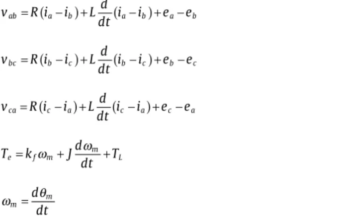
Speed control system for BLDC motor is represented inFig. 1. Three phase star connected brushless dc motor can be described by the following five equations(1) to (5)as,
v R i i L d dt i i e e ab=
(
a− b)
+(
a− b)
+ −a b (1) v R i i L d dt i i e e bc=(
b−c)
+(
b− c)
+ b− c (2) v R i i Ld dt i i e e ca=(
c− a)
+(
c− a)
+ −c a (3) T k Jd dt T e f m m L =ω
+ω
+ (4)ω
mθ
m d dt = (5)Where Vab, Vbc, and Vcaare the phase to phase voltage in volts. Phase currents of the stator winding represents by ia, ib, and icin amperes. L denotes the self inductance of the motor in Henry. Back electromagnetic force is represented by ea, eb, and ecin volts. Teand TLare the electromagnetic torque and Load torque of the motor in N-m. J is the rotor inertia, kfis a friction constant, ωmis the rotor speed of the motor in rad/s, and θmis the rotor position of the motor in rad.Fig. 1shows the speed control system of the brushless dc motor. The system consists of two loops, such as the inner loop and the outer loop. Inner loop is used for synchronizing the inverting gate signal with back electro motive force or rotor position of the motor. The outer loop is used to sense the actual speed of the motor, and then it is compared with the reference speed to produce speed error. The speed error is then processed via controller thus provide
the controlling signal to the switching logic and PWM inverter and control the dc bus voltage thus by controlling the speed of the motor
[7].
3. Design of fuzzy PD and fuzzy PID type speed controller for the brushless DC motor
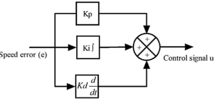
Structure of conventional PID controller is shown inFig. 2. The control output of the PID controller in time-domain is expressed in equation(6)as,
u t K e t K e t dt K de
dt
p i d
( )
=( )
+∫
( )
+ (6)Where, e (t) represents the tracking speed error, the difference between the desired input value (ωref), and the actual output (ωact), u(t) is the control signal to the plant, Kpis the proportional gain, Kiis the integral gain, and Kdis derivative gain of the PID control-ler. The design of fuzzy PD controller and fuzzy PID controller is given below, and their structures are shown inFigs. 3 and 4.
The proportional derivative controller uses the derivative action to improve closed-loop stability. The basic description of a PD con-troller is expressed in the equation(7)as,
u t K e t K de t
dt
p d
( )
=( )
+( )
(7)The input to the fuzzy PD controller is the error and rate of change of error, the control output is the nonlinear function of error and rate of change of error and given in the equation(8)as,
u t f K e t K de t
dt K
e ce u
( )
= ⎛⎝⎜ ∗( )
, ∗( )
⎞⎠⎟ ∗ (8)The function f is the input–output map of the fuzzy controller. Using the linear approximation, the equation(8)rewrite as,
u t K e t K de t dt K e ce u
( )
=⎛⎝⎜ ∗( )
+ ∗( )
⎞⎠⎟ ∗ (9) u t K K e t K K de t dt e u ce u( )
= ∗ ∗( )
+ ∗ ∗( )
(10)By comparing, the gains in (7) and (10) are related in the fol-lowing equation(11)and(12)as,
Kp=Ke∗Ku (11)
Kd =Kce∗Ku (12)
Where, Keand Kceare input scaling factor of the fuzzy PD con-troller. Kuis the output scaling factor of the fuzzy PD controller. It has simple control structure which gives better sensitivity and in-creases the overall stability of the closed loop system. Also this structure provides reduced overshoot and enhanced damping to the overall closed loop system. The nonlinearity of the system can be handled by appropriate choice of input and output membership func-tions[9].
The internal structure of Fuzzy PD controller has two inputs that are error (e) and rate of change of error (Δe) and one output (U), and it is shown inFig. 5. The inputs are distributed with five tri-angular membership functions.
Fuzzy inference system is modeled by zero order Takagi-Sugeno fuzzy inference system. The triangular membership function is de-scribed by the equation(13)as,
f x a b c x x a b a a x b c x c b b x c c x j j j j j j j j j j j , , , , , , ,
(
)
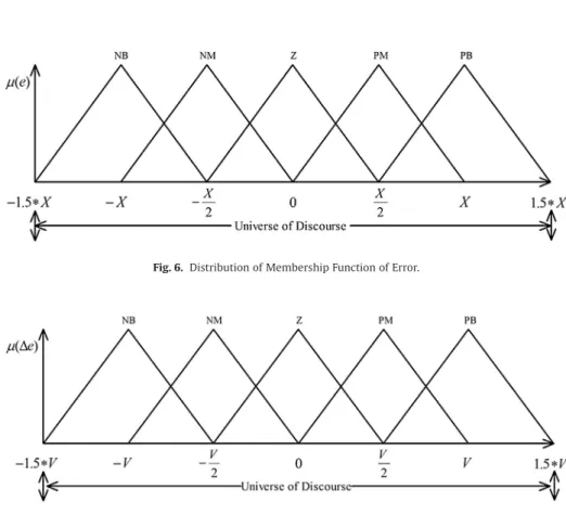
= ≤ − − ≤ ≤ − − ≤ ≤ ≤ ⎧ ⎨ 0 0 0 ⎪⎪ ⎪ ⎪⎪ ⎩ ⎪ ⎪ ⎪ ⎪ (13)Where a andclocate the feet of the triangle and the parameter blocates the peak. The distribution of membership functions for the error and the rate of change of error are shown inFigs. 6 and 7. Two inputs has range from−1.5*X to 1.5*X and−1.5*V to 1.5*V, respectively, membership function denote by Negative Big (NB), Neg-ative Medium (NM), Zero (Z), Positive Medium (PM), and Positive Big (PB). The range of output is from –H to H. The distribution of output is shown inFig. 8. Initially, 25 rules created for fuzzy PD con-troller and, the overall fuzzy rule is shown inTable 1.Fig. 9shows the fuzzy reasoning procedure for a zero order Takagi-Sugeno fuzzy inference system. The fuzzy part is only in its antecedent. Each rule has a crisp output, and the overall output is obtained via weighted average. This fuzzy procedure avoids the time consuming process of defuzzification required in a Mamdani fuzzy model.
Fig. 2. Structure of conventional PID controller.
Fig. 3. Structure of fuzzy PD type controller.
Fig. 4.Structure of fuzzy PID type controller.
Table 1
Initial rule base for fuzzy PD controller.
e/Δe NB NM Z PM PB NB NB NB PM NM NM NM NB NM Z Z Z Z NB NM Z PM PB PM Z Z Z PM PB PB PM PM PM PB PB
The fuzzy PD controller has three scaling parameters, i.e., Ke, Kce, and Ku, and it has three adjustable parameters for the input mem-bership function and coefficient of consequent part, i.e., X, V, and H. By varying this parameter, the optimal solution for the speed control of the brushless dc motor is obtained. This parameter is tuned by using particle swarm optimization, cuckoo search and bat algo-rithm, and it has been outlined in section V.
Regarding the design of fuzzy PID controller, it is straightfor-ward to imagine a fuzzy PID with three input terms: error, integral error, and derivative error. A rule base with three inputs and output will increase the fuzzy rules as mentioned in literature survey, and also, rules concerning the integral action are troublesome[12]. There-fore, it is common to separate the integral action as in the Fuzzy PD plus Integral controller (also known as fuzzy PID controller) in
Fig. 4. The control output is computed and expressed in equation
(14)as,
u t K e t K de t
dt e t dt K
e ce u
( )
=⎛⎝⎜( )
+( )
+∫
( )
⎞⎠⎟ ∗ (14) By comparing, the gains in (14) and (6) are related in the fol-lowing equation(15),(16)and(17)as,Kp=Ke∗Ku (15)
Kd=Kce∗Ku (16)
Ki=Ku (17)
This controller provides all the benefits of PID control. The input and output scaling factors of the Fuzzy PID controller are Ke, Kce, and Ku, and it also has three adjustable parameters for the input membership function and coefficient of consequent part, i.e., X, V,
Fig. 5.Internal structure of fuzzy PD controller.
Fig. 6.Distribution of Membership Function of Error.
and H. By adjusting this scaling factor and adjustable parameters, optimal results for the speed control of the brushless dc motor can be obtained. The fuzzy PID controller scaling factor is also tuned by using particle swarm optimization, cuckoo search and bat algo-rithm, and it is discussed in the section V.
4. Formulation of the objective functions for tuning of fuzzy PD and fuzzy PID controller
A system is considered an optimum control system when the system parameters are adjusted so that the index reaches a minimum value. To be useful, a performance index must be a number that is always positive or zero. Then the best system is delineated as the system that minimizes this index.
Four commonly used performance indices for designing single-loop control algorithm are explained as follows.
The root-mean-square error (RMSE) is a frequently used measure of the differences between reference value of the closed loop system and actual output of the system, and it is expressed in equation(18)
as, J t t T ref act i T i i 1 0 2 =
∑
=(
ω
( )
−ω
( )
)
)
(18)Where ω(t)refiis the reference speed in rad/sec, ω(t)actiactual speed of the motor in rad/sec at each sample and T is the total simula-tion time for the optimizasimula-tion. Essentially, the RMSE represents the
Fig. 8. Distribution of coefficient of consequent part of output.
sample standard deviation of the differences between reference input and actual output of the system. RMSE is a good measure of the system accuracy.
A fairly useful performance index is the integral of absolute error (IAE), and it is expressed in the equation(19)as,
J t ref t actdt
T
2 0
=
∫
ω
( )
−ω
( )
(19)IAE integrates the absolute error over time. It doesn’t add weight to any of the errors in a systems response. It tends to produce a slower response in the system but results in a fairly good under damped system.
A very useful criterion that penalizes long duration transient is known as the integral of time multiplied absolute error (ITAE). It is expressed in equation(20)as,
J t t t dt T ref act 3 0 =
∫
∗(
ω
( )
−ω
( )
)
(20)The ITAE criterion tries to minimize time multiplied absolute error of the control system. The time multiplication term penalizes the error more at the later stages than at the start and therefore effec-tively reduces the settling time.
Another useful performance index is the integral of the square of the error (ISE) criterion, and it is expressed in equation(21)as,
J t ref t act dt T 4 2 0 =
∫
(
ω
( )
−ω
( )
)
(21)By focusing on the square of the error function. It penalizes pos-itive and negative values of the error.
In addition, in order to improve the system performance, one more performance indices is introduced in this paper, i.e., addi-tion of the four performance indices (RMSE+IAE+ITAE+ISE), and it is expressed in equation(22)as,
J5= +J1 J2+J3+J4 (22)
The five performance indices are considered as the objective func-tion used for fuzzy PD and fuzzy PID controller tuning to ensure stability and attain superior damping to sudden load disturbance and set speed change.
5. Review of nature-inspired optimization algorithms for tuning of fuzzy PD and fuzzy PID controller
Optimization methods are extensively applied in numerous domain fields’ areas such as electrical engineering, electronics engineering, and mechanical engineering, etc. During the last couple of years, many optimization algorithms have been created based on the nature inspired resemblance. However, these algo-rithms are not always able to solve some problems in the best way. Although it has been shown that these are good methods to solve complex problems, there are no methods yet to know the optimal parameters to solve problems that can be set at the beginning when using the algorithms. In this section, we briefly described the optimization algorithms used in this paper, i.e., particle swarm optimization, cuckoo search algorithm, and bat search algorithm for tuning of the input and output scaling factor and parameter of antecedent and consequent part of the fuzzy PD and fuzzy PID controller. The following subsections briefly de-scribe the basic theory of each algorithm in its original form. This description is considered necessary to grasp the ideas behind the use of fuzzy PD and Fuzzy PID logic in enhancing the original Meta-heuristic methods by providing them with dynamic param-eter adaptation capabilities.
5.1. Particle swarm optimization
Particle Swarm Optimization (PSO) is a population based sto-chastic optimization technique developed by Kennedy and Eberhart in 1995 inspired by the social behavior of bird flocking or fish school-ing. The particle swarm concept was motivated from the simulation of social behavior. PSO requires only primitive mathematical op-erators, and is computationally inexpensive in terms of both memory requirements and time. A swarm in PSO consists of a number of par-ticles. Each particle represents a potential solution to the optimization task. Each particle represents a candidate solution. Each particle moves to a new position according to the new velocity which in-cludes its previous velocity and the moving vectors according to the past best solution and global best solution. The best solution is then kept; each particle accelerates in the directions of not only the local best solution but also the global best position. If a particle discov-ers a new probable solution, other particles will move closer to it in order to explore the region. The basic steps for PSO are given in the flowchart as shown inFig. 10.
A swarm is composed of m particles flying in the D-dimension in a certain speed. Every particle changes its position on the basis of considering its own historical best position and other particles’ historical best position. The position for the ith particle is
xi=
(
xi1,xi2,…xiD)
, where 1≤i≤m and m is the size of the particleswarm. The speed for the ith particle is vi=
(
vi1,vi2,…viD)
,where 1≤i≤D and D is the dimension of search space. The histor-ical best position for the ith particle (pbest) is pi=
(
pi1,pi2,…piD)
.The best position for the whole swarm (gbest) is
pg=
(
pg1,pg2,…pgm)
g∈{
1 2, ,…m}
.The speed and the position of the particle can be updated by the following formulations:
vid
(
t+ =1)
vid( )
t +c r p1 1(
id( )
t −xid( )
t)
+c r p2 2(
gd( )
t −xid( )
t)
(23)xid
(
t+ =1)
xid( )
t +vid(
t+1)
(24)Where c1and c2are learning factors and are positive constant,
xid
( )
t is the position vector for the ith particle,vid( )
t is theasso-ciated speed vector. Due to the learning factor, the particles have the capability of self-summing up and learning from the excellent individual of the group, the particle could be close to its own his-torical best position as well as to the hishis-torical best position of the group. The learning factors c1and c2are usually set as 2. The values of r1and r2are randomly distributed in [0,1]. The speed of par-ticles is restricted within the maximum speed Vmax. Shi and Eberhart introduced the idea of inertia weight to improve an algorithm’s as-tringency, and the revised formulation of the speed is shown in following equation,
vid
(
t+ =1)
ω
vid( )
t +c r p1 1(
id( )
t −xid( )
t)
+c r p2 2(
gd( )
t −xid( )
t)
(25)Where ω is the inertia weight, the value of which decides the quantity inherited from the current speed of the particle. If it is chosen properly, then the particle will have the balanced ability of exploitation and development.
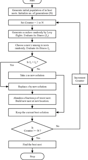
5.2. Cuckoo search algorithm
In 2009, Xin-She Yang and Suash Deb proposed a new metaheuristic optimization technique named Cuckoo search algo-rithm. It is based on the brood parasitic breeding behavior of some species of cuckoos. It follows the cuckoo’s strategy of finding other bird’s nest where they would lay eggs. Cuckoos try to find a nest in which host has just laid its eggs so that their eggs would hatch before the host because of this fact that cuckoo eggs hatch earlier than their host eggs. Other interesting feature of cuckoo birds is the mimicry in color and pattern of eggs of some of the host species. It would help in their ability to reproduce and survival of eggs or their chick. The cuckoo’s chick forced out the egg or young of the host from the nest. It would increase its share in food by frequent calling and by mimic the call of host’s chick. Some host birds are able to detect the contamination of their nest by cuckoos or they can distinguish between their eggs and cuckoo’s eggs, then they will either throw these foreigner eggs or vacate their nest and develop a new shelter or nest. The main theme of this algorithm is to choose the best nest with potentially good solutions or eggs. Each nest is a representative of a potential candidate[16,17]. The three signif-icant rules that are used for implementing CSA algorithm are discussed as follow:
1. Each cuckoo lays single egg and places it in an arbitrarily chosen nest.
2. The best nests carry the potential solution which will move onto next generation.
3. The available host nests are limited and a host bird can find the foreign eggs by a probability ‘p’ which ranges [0, 1].
For generating a new nest for cuckoos, a law named Levy flight is used which is as follows:
x tc
(
+1)
=x tc( )
+α
0⊕Levy( )
λ
0 (26) Where α0(α0>0) is step size and is related to the problem speci-fied in the equation(26)represents a random walk which is a Markov chain which means its next step depends on the current location and the transition probability. The random walk proves to be more promising in exploring the search space due to its longer step length in long run. The Levy flight is characterized by random walk whichis derived from the Levy distribution with an infinite variance and infinite mean. The Levy distribution in the proposed CSA is devel-oped using the exponential law proposed by Mantegna. In this, the step size should be taken as λ0/100, where λ0is the search space size as Levy distribution may be too strong for larger step size that new solutions may be opted out from the searched space[24]. The basic steps for CSA are given in the flowchart as shown inFig. 11.
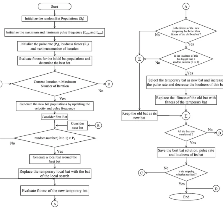
5.3. BAT algorithm
The bat algorithm uses the echolocation behavior of bats. These bats emit a very loud sound pulse (echolocation) and listens for the echo that bounces back from the surrounding objects. Their signal bandwidth varies depending on the species. Each sound pulse in-cludes frequency, loudness, and pulse emission rate. Most bats use signals with tuning frequencies while the rest use fixed-frequency signals. The frequency range used by these creatures is between 25
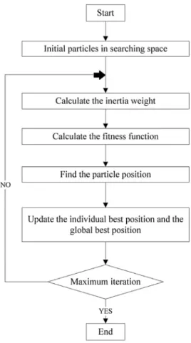
KHz to 150 KHz. Bat algorithms are based on the following aspects; all bats use echolocation and distinguish the difference between victim and obstruction. Bats are flying with a random velocity, in a random location, with a variable frequency, loudness, and the pulse emission rate[19,20,25]. Bat algorithm is bad at exploration and exploitation. In order to tackle with the problem mentioned above, distribution of the population modification structure has been pro-posed for the original algorithm. The flowchart for the propro-posed bat algorithm is shown inFig. 12. Bat algorithm for optimization of tuning of the adjustable parameter in fuzzy PD and fuzzy PID con-troller as follows:
Step1:
Formulation of Objective function J(S) for optimization with S=(S1. . . Sd), where d is the number of tuning parameter. The fitness function can be defined as a particular type of ob-jective function that is used to summarize, as a single figure of merit. In general, the fitness function should be a
measure of how closely the model prediction matches the ob-served or expected data for a given set of model parameters. The notion of fitness is fundamental to the application of evolution-ary algorithms; the degree of success in their application may depend critically on the definition of a fitness that changes neither too rapidly nor too slowly with the design parameters of the op-timization problem. The fitness function must guarantee that individuals can be differentiated according to their suitability for solving the optimization problem.
In evolutionary algorithms, the performance of the individual run is measured by a fitness function. After each iteration, the members are given a performance measure derived from the fitness function, and the “fittest” members of the population will propagate for the next iteration. In this paper, to assure stabil-ity and attain superior damping to sudden load disturbance and set speed variations, the parameters of the controllers may be chosen to minimize the objective function described by the equa-tions (18–22) is considered as a fitness function for the
Table 2
Parameters of the PSO, Cuckoo, and Bat algorithm.
PSO Cuckoo search Bat algorithm
Generation 10 Generation 10 Generation 10
Population size 10 Number of nests 10 Population size 10
Cognitive parameter (c1) 2 Discovery rate (pa) 0.25 β=σ 0.9
Social parameter (c2) 2 P10 0.9
Initial weight (Wmin) 0.9 R10 0.9
Final weight (Wmax) 0.4 fmin 0
fmax 100
Trial 50 Trial 50 Trial 50
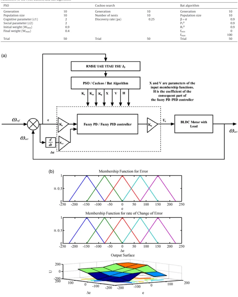
(a)
(b)
Fig. 13. (a). Optimization of the fuzzy PD, fuzzy PID controller using PSO, Cuckoo search and Bat algorithm. (b). Initial membership function for error, rate of change of error and output surface of fuzzy PD and fuzzy PID controller.
Table 3
Optimal value of tuning parameter of the Fuzzy PD controller with PSO, Cuckoo search and Bat algorithm. RMSE (J1)
Algorithm Ke Kce Ku H X V Best Worst Mean Standard deviation Average computation time (sec)
PSO 66.7792 139.0034 14.3992 56.4864 82.2190 16.9855 0.1074 0.1550 0.1204 0.0186 429.7240 Cuckoo 36.0998 111.5952 58.1305 36.9542 101.9201 110.7451 0.1235 0.1554 0.1315 0.0104 642.5300 Bat 118.8531 143.9291 98.3967 5.4544 127.3857 140.1068 0.1026 0.1557 0.1074 0.0160 248.7020 IAE (J2)
Algorithm Ke Kce Ku H X V Best Worst Mean Standard deviation Average computation time (sec)
PSO 150.0000 0.1000 19.9640 82.3017 131.0437 150.0000 0.0082 0.0134 0.0095 0.0020 387.4590 Cuckoo 0.4399 0.9269 137.4575 97.3321 4.5031 149.5709 0.0091 0.0133 0.0102 0.0015 909.3230 Bat 66.1901 8.6379 42.3185 64.3631 85.0581 44.1775 0.0080 0.0134 0.0085 0.0016 252.8630 ITAE (J3)
Algorithm Ke Kce Ku H X V Best Worst Mean Standard deviation Average computation time (sec)
PSO 48.5968 147.0557 50.4469 48.6462 61.7448 147.1379 0.0005 0.0014 0.0007 0.0003 384.1950 Cuckoo 82.2899 94.4075 24.8378 149.7029 150.0000 63.9726 0.0005 0.0014 0.0008 0.0004 603.4860 Bat 104.3006 10.2912 38.2921 33.6826 100.2072 126.6734 0.0004 0.0009 0.0005 0.0002 271.4610 ISE (J4)
Algorithm Ke Kce Ku H X V Best Worst Mean Standard deviation Average computation time (sec)
PSO 26.2795 81.5246 26.6294 125.1210 148.0905 75.6607 0.0031 0.0096 0.0045 0.0022 426.7350 Cuckoo 4.7749 89.7148 61.6997 113.4746 81.9585 149.9967 0.0032 0.0093 0.0048 0.0023 540.2730 Bat 72.6903 126.7381 31.4841 82.8827 94.5138 4.8897 0.0030 0.0094 0.0036 0.0019 263.7860 RMSE+IAE+ITAE+ISE (J5)
Algorithm Ke Kce Ku H X V Best Worst Mean Standard deviation Average Computation Time (sec)
PSO 10.3533 19.7405 50.7451 99.9594 83.7049 150.0000 0.1381 0.1525 0.1440 0.0052 405.4830 Cuckoo 36.5949 79.8609 24.5980 78.3844 99.9910 49.4134 0.1221 0.1521 0.1281 0.0102 483.2470 Bat 16.0324 17.1473 117.9016 44.0223 90.7856 144.8829 0.1138 0.1538 0.1175 0.0121 305.2550
optimization,
For fuzzy PD and fuzzy PID controller: d=6, S1=Ke, S2=Kce, S3=Ku, S4=H, S5=X, and S6=V.
The range for tuning parameter in fuzzy PD controller and fuzzy PID controller is given in equation(27)as,
0<Ke Kce Ku H X, , , , , and V ≤150 (27)
Sep 2:Initialize the bat population Siand initial velocity Lifor (i=1, 2. . . n), where n is the number of bat populations.
Step 3:Define pulse frequency fiat Si. Initialize pulse rates Pi, maximum number of iterations and the loudness factor Ri
Step 4:Loop: Start; t=0;
While (t<Maximum number of iterations) t=t+1; iteration count.
Generate new solutions by adjusting frequency and updating ve-locities and locations/solutions by the equation (28–30)
fi=fmin+
(
fmax−fmin)
γ
(28)Lti=Lti−1+
(
Sti−1−S fb)
i (29)Sit=Sit−1+Lti (30)
Where, γ is a random vector drawn from a uniform distribu-tion and frequency range fmin=0 and fmax=100. Sbis a global best for every iteration or generation.
The second term of the Equation(29)provides local search with guidance of the best solution in the standard algorithm. Exclusive usage of this term may cause premature convergence problem, thus solutions get stuck at a local minimum. When the best solution is near a local minimum toward the end of optimization process, the ithsolution can have no chance to get away from that undesired local minimum as the movement of the ithparticle depends on such best solution toward the end of the optimization process[26]. For this purpose, the velocity equation has been modified to perform the situation that the kthsolution could also affect the ithsolution. The equation(29)modified as,
Lti=Lti−1+
(
Sit−S fb)
iξ
1+(
Sti −Skt)
fiξ
2ξ ξ
1+ =2 1Where Skis one of the best solutions randomly chosen among the population
(
i≠k)
,ξ1is learning factor ranging fromωmintoωmax.As the value of ξ1increases, the effect of the best solution (Sb) is higher than the kthsolution and vice versa. The ξ
1value has to be updated as iterations proceed in order that the solution can switch from global to local search.
ξ ω
1= max(
1−e−iter)
+ω
minWhere, “iter” is the current iteration number,ωmaxandωminare
maximum and minimum inertia weight. The inertia weights of the optimization are chosen as 0.9 and 0.1 respectively. This proce-dure called as distribution of the population modification structure.
If (random number (0 to 1)>Pi)
Select a solution among the best solutions and generate a local solution around the selected best solution using the equation(31),
Si S R
t b
t
= + ε (31)
Where, ε is a random number. While Rt= <Rti>is the average loudness of all the bats at this time step (t).
End if
Generate a new solution by flying randomly If (random number (0 to 1)<Ri& J(Si)<J(Sb)) Accept the new solutions,
Increase Piand reduce Riusing equation(32)and(33).
Rit+1=
β
Rit, Pit+1=Pi0(
1−e(−σt))
(32) Where, β and σ are constants. For any 0<β<1 and σ>0, we haveRi P P as t t i t i →0 = 0 → ∞ , , (33)
For simplicity, β=σ can be used, and for this work, β=σ=0.9 is considered.
End if
Rank the bats and find the current best (Sb) End while
Loop end
Step 5:Display the optimum solutions.
Bat algorithm has many advantages, and one of the key advan-tages is that it can provide very quick convergence at a very initial stage by switching from exploration to exploitation. This makes it an efficient algorithm for applications such as classifications and others when a quick solution is needed. There are many reasons for the success of bat-based algorithms. By analyzing the key features and updating equations, we can summarize the following three key points/features:
•
Frequency tuning: Bat algorithm uses echolocation and frequen-cy tuning to solve problems. Though echolocation is not directly used to mimic the true function in reality, frequency variations are used. This capability can provide some functionality that may be similar to the key feature used in particle swarm optimiza-tion and harmony search. Therefore, bat algorithm possesses the advantages of other swarm-intelligence-based algorithms.•
Automatic zooming: Bat algorithm has a distinct advantage over other metaheuristic algorithms. That is, Bat algorithm has a ca-pability of automatically zooming into a region where promising solutions have been found. This zooming is accompanied by the automatic switch from explorative moves to local intensive ex-ploitation. As a result, bat algorithm has a quick convergence rate, at least at early stages of the iterations, compared with other algorithms.•
Parameter control: Many metaheuristic algorithms used fixed pa-rameters by using some, pre-tuned algorithm-dependent parameters. In contrast, bat algorithm uses parameter control, which can vary the values of parameters (P and R) as the itera-tions proceed. This provides a way to automatically switch from exploration to exploitation when the optimal solution is ap-proaching. This gives another advantage of bat algorithm over other metaheuristic algorithms.Likely many metaheuristic algorithms, bat algorithm has the ad-vantage of simplicity and flexibility. Bat algorithm is easy to implement, and such a simple algorithm can be very flexible to solve a wide range of problems as we have seen in the above review. In addition, preliminary theoretical analysis by Huang suggested that Bat algorithm has guaranteed global convergence properties under the right condition, and bat algorithm can also solve large-scale prob-lems effectively[27,28].
6. Simulation results and discussions
In this section, the superiority of particle swarm, cuckoo search, and bat algorithms optimized fuzzy PD controller over particle swarm, cuckoo search, and bat algorithms optimized fuzzy PID con-troller is proved through simulation for the speed control of BLDC motor. The parameters of the considered algorithms are given in
Table 2. PSO, Cuckoo and bat algorithm progressively minimize the objective functions (18) to (22) over the iterations while finding optimal set of parameters for the fuzzy PD and fuzzy PID control-ler. The program stops if the value of the objective function does not change appreciably over consecutive iterations (i.e. the change is less than the pre-specified tolerance level) or the maximum number of iterations is exceeded. The maximum number of itera-tions is kept as 10 and the tolerance level is kept at 10−6. With a population of P=10 individuals for G=10 generations, the fitness function in Equation(18) to (22)are evaluated 100 times. Indeed, this number (E=P x G) represents the act of evaluating points inside the search space. The optimization procedure is performed using Matlab-R2010a, M-file under Windows 7 on a PC Pentium dual core processor CPU, and 2.1 GHz speed system. Totally, 50 trials have been performed, in order to be definite that convergence has taken place and 5000 function has been evaluated for 50 trails.
Fig. 13(a) shows the optimization of the fuzzy PD, fuzzy PID con-troller using PSO, Cuckoo search and Bat algorithm.
Fig. 18. Convergence graph for tuning parameter of the fuzzy PID controller.
Table 4
Optimal value of tuning parameter of the Fuzzy PID controller with PSO, Cuckoo search and Bat algorithm. RMSE (J1)
Algorithm Ke Kce Ku H X V Best Worst Mean Standard deviation Average computation time (sec)
PSO 88.2954 144.5239 12.9768 75.1248 78.2863 13.6159 0.1084 0.1391 0.1159 0.0108 384.4700 Cuckoo 90.3794 125.3976 101.0240 13.9376 126.4255 51.8392 0.1109 0.1570 0.1270 0.0146 516.1440 Bat 28.9570 18.5499 30.9032 22.0622 28.4416 6.4933 0.1082 0.1240 0.1097 0.0048 257.8630 IAE (J2)
Algorithm Ke Kce Ku H X V Best Worst Mean Standard deviation Average computation time (sec)
PSO 57.0861 150.0000 68.6791 25.0706 58.6882 130.6920 0.0082 0.0120 0.0091 0.0014 373.5650 Cuckoo 33.3408 135.1884 51.7629 122.8613 92.1014 137.6761 0.0086 0.0146 0.0093 0.0018 603.7420 Bat 6.3802 16.1419 92.5163 140.9666 53.2443 61.6647 0.0082 0.0134 0.0087 0.0016 342.8120 ITAE (J3)
Algorithm Ke Kce Ku H X V Best Worst Mean Standard deviation Average computation time (sec)
PSO 66.9731 37.7918 85.3110 33.2685 116.7263 102.1748 0.0005 0.0014 0.0008 0.0003 407.5620 Cuckoo 31.2468 71.9042 65.6869 63.1240 67.8707 78.4008 0.0005 0.0013 0.0007 0.0003 521.6800 Bat 75.6367 97.0607 46.2350 20.8988 71.3923 54.4366 0.0004 0.0007 0.0005 0.0001 289.6610 ISE (J4)
Algorithm Ke Kce Ku H X V Best Worst Mean Standard deviation Average computation time (sec)
PSO 100.834 65.0621 4.8456 141.1888 150.0000 150.0000 0.0031 0.0093 0.0046 0.0023 393.6480 Cuckoo 39.0057 147.9450 16.2927 56.4042 56.0387 205.6135 0.0031 0.0092 0.0045 0.0021 558.8910 Bat 111.072 69.2280 95.1338 4.5961 112.9094 106.1842 0.0029 0.0042 0.0030 0.0004 262.9670 RMSE+IAE+ITAE+ISE (J5)
Algorithm Ke Kce Ku H X V Best Worst Mean Standard deviation Average computation time (sec)
PSO 13.1549 118.2739 150.0000 47.2018 118.4169 27.6085 0.1193 0.1498 0.1241 0.0095 419.4700 Cuckoo 80.3004 88.3897 24.7887 144.4952 128.5186 46.6502 0.1329 0.1498 0.1394 0.0061 518.0000 Bat 66.2040 143.4404 18.6981 70.6740 128.5554 6.6109 0.1103 0.1437 0.1133 0.0101 290.3320
Fig. 19. Error membership function of fuzzy PID controller after optimization using PSO, Cuckoo search and bat algorithm.
Fig. 13(b) shows the initial guess for the error and rate of change error membership functions and output surface of the fuzzy PD and fuzzy PID controller. Initial values for input and output scaling factor of the fuzzy PD and fuzzy PID controller are Ke=150, Kce=150 and Ku=150. Initial values of antecedent and consequent part of the fuzzy PD and fuzzy PID controller are X=V=H=150.
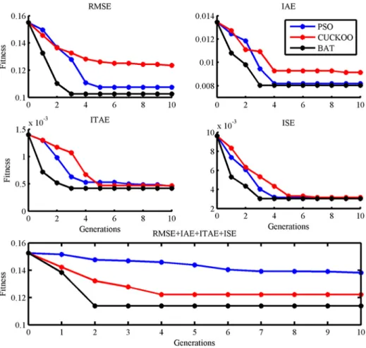
Fig. 14shows the convergence graph of above stated algo-rithms for tuning of fuzzy PD controller. The tuning parameter of the fuzzy PD controller with considered algorithms are shown in
Table 3. The objective function value for final best population is best only for bat algorithm over PSO and Cuckoo search, and also, the average computation time taken by the bat algorithm is less than PSO and Cuckoo search. From the convergence graph andTable 3, bat algorithm has superior objective function value and less average computation time than other two algorithms.
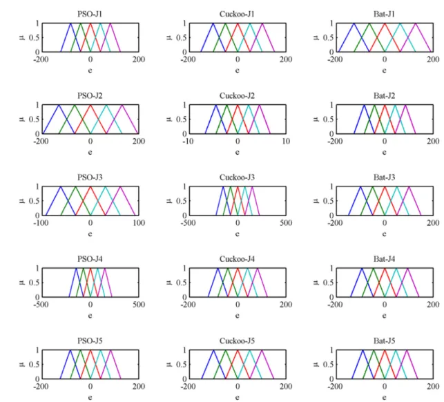
Fig. 15shows the after optimization of the error membership function of the fuzzy PD controller using PSO, Cuckoo search and bat algorithm with five objective functions.Fig. 16shows the after optimization of the rate of change of membership function for the fuzzy PD controller using PSO, Cuckoo search and bat algorithm with five objective functions.Fig. 17shows the after optimization of the output surface of the fuzzy PD controller with five objective functions.
Fig. 18shows the convergence graph for the tuning parameters of the fuzzy PID controller. Optimization results for the fuzzy PID controller are shown inTable 4. The objective function value is
only best for the bat algorithm over PSO and cuckoo search. And also the average computation time is less for bat algorithm than PSO and cuckoo search. Again, bat algorithm has outperformed the other two algorithms since minimum objective function value and less computation time is obtained than other two algorithms.
Fig. 19 shows the after optimization of the error membership function of the fuzzy PID controller using PSO, Cuckoo search and bat algorithm with five objective functions. Fig. 20 shows the after optimization of the rate of change of membership function for the fuzzy PID controller using PSO, Cuckoo search and bat algorithm with five objective functions.Fig. 21shows the after optimization of the output surface of the fuzzy PID controller with five objective functions.
When compared with the objective values and average compu-tation times inTables 3 and 4, bat algorithm optimized fuzzy PD controller has minimum objective function value and less compu-tation time than the others. In order to validate effectiveness of the bat algorithm tuned fuzzy PD controller, it is compared with bat, PSO, and cuckoo search algorithm tuned fuzzy PID controller. The BLDC motor is operated for different operating conditions with above controller. Also, the time domain specification such as overshoot, undershoot, recovery time, and steady state error, settling time and performance indices such RMSE, IAE, ITAE, ISE are compared with for the above considered controllers.
Three operating conditions are considered for proving the ef-fectiveness of the controller.
Condition 1 The reference speed is set to 200 rad/s with no load conditions. The time domain specification and performance indices for the speed response under fuzzy PD and fuzzy PID controllers are provided inTable 5. From these results, optimization with ob-jective function J5 (PSO, Cuckoo, and Bat algorithm) produces better results than other objective function (J1, J2, J3 and J4). The simu-lation result for the condition 1 with objective function J5 is shown in theFig. 22. From these results, bat optimized fuzzy PD; fuzzy PID controller (objective function J5) has better time domain specifi-cation and performance indices than other algorithms. Therefore, these two are compared. Bat algorithm optimized fuzzy PD con-troller (objective function J5) shows better performance than bat optimized fuzzy PID controller (objective function J5). Because steady state error of speed of the motor has 0.0472 for bat optimized fuzzy PD controller (objective function J5) but 0.0535 for bat op-timized fuzzy PID controller(objective function J5), total indices is 0.2825 for bat optimized fuzzy PD controller(objective function J5) but 0.2840 for bat optimized fuzzy PID controller(objective func-tion J5). From the results, it is clear that bat optimized fuzzy PD controller (objective function J5) has superior performance in all aspects.
Condition 2 In order to validate the effectiveness of the controller for realistic working conditions, load disturbance is introduced and performance is checked. The reference speed is set to 200 rad/s, and load is varied from no load to full load condition at 0.2s. The time domain specification and performance indices for the speed re-sponse are presented inTable 6. From these results, optimization with objective function J5 (PSO, Cuckoo, and Bat algorithm)
pro-duces better results than other objective function (J1, J2, J3 and J4). The simulation result for the conditions 2 with objective function J5 is shown in theFig. 23. From the results, it is ascertained that bat optimized fuzzy PD controller (objective function J5) has clear edge over other algorithms. Bat algorithm optimized fuzzy PD con-troller (objective function J5) shows better performance in overshoot (0.2458), undershoot (0.3992), recovery time (0.3992 s), steady state error (0.0345 rad/s), and it has high quality of performance indices compared to other considered controllers.
Condition 3 In order to ascertain the efficiency of the controller for realistic working conditions, change in set speed condition is in-troduced and performance is checked. Initially the reference speed set as 200 rad/s at no load condition. At 0.2 s, the reference speed is changed to 100 rad/s. For this set speed change condition, the time domain specifications such as undershoot, recovery time and steady state error and performance indices are presented inTable 7. From these results, optimization with objective function J5 (PSO, Cuckoo, and Bat algorithm) produces better results than other ob-jective function (J1, J2, J3 and J4). The simulation results are shown inFig. 24.
Similar to the previous two conditions, for this condition 3 also, bat algorithm optimized fuzzy PD controller (objective function J5) has shown superior performance than the other controllers, and it is evident from the test results of time domain specifications and performance indices considered. The parameters value obtained are very much enhanced than the other controllers. All the values are in favor of bat optimized fuzzy PD controller (objective function J5).
Table 5
Performance parameters for condition 1. PSO
Objective function Controller Time domain specifications Performance indices Total indices
Rise time Overshoot Settling time Steady state error RMSE IAE ITAE ISE
J1 Fuzzy PD 0.0119 4.0271 0.0331 0.0585 0.1837 0.0092 0.0001 0.0047 4.3284 Fuzzy PID 0.0123 2.1769 0.0286 0.0564 0.1837 0.0086 0.0001 0.0045 2.4712 J2 Fuzzy PD 0.0118 4.4244 0.0362 0.0656 0.2017 0.0080 0.0001 0.0037 4.7516 Fuzzy PID 0.0118 4.4244 0.0351 0.0615 0.1964 0.0081 0.0001 0.0037 4.7410 J3 Fuzzy PD 0.0118 4.4244 0.0352 0.0668 0.2039 0.0080 0.0001 0.0037 4.7538 Fuzzy PID 0.0118 4.4244 0.0351 0.0630 0.1984 0.0081 0.0001 0.0037 4.7445 J4 Fuzzy PD 0.0135 0.0000 0.0308 0.0589 0.1876 0.0071 0.0001 0.0032 0.3014 Fuzzy PID 0.0135 0.0000 0.0329 0.0617 0.1875 0.0074 0.0001 0.0032 0.3064 J5 Fuzzy PD 0.0135 0.0000 0.0310 0.0590 0.1976 0.0086 0.0001 0.0032 0.313 Fuzzy PID 0.0123 0.0000 0.0295 0.0557 0.1935 0.0097 0.0001 0.0045 0.3053 Cuckoo search
Objective function Controller Time domain specifications Performance indices Total Indices
Rise time Overshoot Settling time Steady state error RMSE IAE ITAE ISE
J1 Fuzzy PD 0.0135 0.0000 0.0297 0.0570 0.1977 0.0069 0.0001 0.0047 0.3097 Fuzzy PID 0.0123 2.4594 0.0295 0.0578 0.1852 0.0087 0.0001 0.0045 2.7576 J2 Fuzzy PD 0.0118 4.4244 0.0344 0.0601 0.1938 0.0081 0.0001 0.0037 4.7364 Fuzzy PID 0.0118 4.4244 0.0352 0.0635 0.2004 0.0081 0.0001 0.0037 4.7471 J3 Fuzzy PD 0.0118 4.4244 0.0352 0.0629 0.1997 0.0080 0.0001 0.0037 4.7458 Fuzzy PID 0.0118 4.4244 0.0352 0.0660 0.2035 0.0080 0.0001 0.0037 4.7527 J4 Fuzzy PD 0.0135 0.0000 0.0480 0.0626 0.1880 0.0075 0.0001 0.0032 0.3230 Fuzzy PID 0.0135 0.0000 0.0308 0.0583 0.1974 0.0097 0.0001 0.0043 0.3143 J5 Fuzzy PD 0.0126 0.0000 0.0219 0.0565 0.1951 0.0086 0.0001 0.0035 0.2984 Fuzzy PID 0.0118 0.0000 0.0263 0.0514 0.1924 0.0091 0.0001 0.0047 0.3059 Bat algorithm
Objective function Controller Time domain specifications Performance indices Total Indices
Rise time Overshoot Settling time Steady state error RMSE IAE ITAE ISE
J1 Fuzzy PD 0.0135 0.0000 0.0310 0.0604 0.1878 0.0072 0.0001 0.0032 0.3034 Fuzzy PID 0.0126 1.1161 0.0219 0.0566 0.1806 0.0086 0.0001 0.0044 1.4011 J2 Fuzzy PD 0.0118 4.4244 0.0352 0.0634 0.1993 0.0081 0.0001 0.0037 4.7460 Fuzzy PID 0.0118 4.4244 0.0351 0.0638 0.1992 0.0081 0.0001 0.0037 4.7462 J3 Fuzzy PD 0.0118 4.4244 0.0344 0.0609 0.1947 0.0081 0.0001 0.0037 4.7381 Fuzzy PID 0.0123 2.4594 0.0295 0.0569 0.1843 0.0087 0.0001 0.0045 2.7558 J4 Fuzzy PD 0.0142 1.6364 0.0298 0.0615 0.1907 0.0078 0.0001 0.0042 1.9447 Fuzzy PID 0.0144 0.0000 0.0487 0.0601 0.1852 0.0071 0.0001 0.0031 0.3187 J5 Fuzzy PD 0.0138 0.0000 0.0304 0.0472 0.1810 0.0067 0.0001 0.0032 0.2825 Fuzzy PID 0.0137 0.0000 0.0205 0.0535 0.1863 0.0067 0.0001 0.0032 0.2840
Fig. 22.Simulation result for the condition 1.
Table 6
Performance parameters for condition 2. PSO
Objective function Controller Time domain specification Performance indices Total indices
Overshoot Recovery time Steady state error RMSE IAE ITAE ISE
J1 Fuzzy PD 0.7314 0.3997 0.0383 0.1276 0.0109 0.0005 0.0048 1.3131 Fuzzy PID 1.4342 0.3988 0.0329 0.1269 0.0098 0.0003 0.0046 2.0075 J2 Fuzzy PD 0.7136 0.3978 0.0353 0.1377 0.0093 0.0003 0.0038 1.2977 Fuzzy PID 1.0748 0.3998 0.0348 0.1359 0.0092 0.0003 0.0038 1.6587 J3 Fuzzy PD 2.3419 0.3977 0.0372 0.1402 0.0094 0.0003 0.0038 2.9305 Fuzzy PID 1.7930 0.3988 0.0360 0.1375 0.0093 0.0003 0.0038 2.3788 J4 Fuzzy PD 0.8293 0.3992 0.0400 0.1309 0.0090 0.0005 0.0033 1.4123 Fuzzy PID 0.8258 0.3997 0.0450 0.1318 0.0098 0.0006 0.0033 1.4160 J5 Fuzzy PD 0.7266 0.3992 0.0323 0.1230 0.0090 0.0003 0.0033 1.2937 Fuzzy PID 0.7266 0.3995 0.0329 0.1265 0.0099 0.0003 0.0033 1.2991 Cuckoo search
Objective function Controller Time domain specification Performance indices Total indices
Overshoot Recovery time Steady state error RMSE IAE ITAE ISE
J1 Fuzzy PD 0.7030 0.3996 0.0369 0.1304 0.0085 0.0004 0.0033 1.2821 Fuzzy PID 0.8227 0.3995 0.0339 0.1270 0.0101 0.0004 0.0046 1.3981 J2 Fuzzy PD 0.6234 0.3971 0.0348 0.1341 0.0093 0.0003 0.0038 1.2029 Fuzzy PID 2.6484 0.3995 0.0363 0.1395 0.0093 0.0003 0.0038 3.2371 J3 Fuzzy PD 3.1059 0.3964 0.0342 0.1367 0.0091 0.0003 0.0038 3.6864 Fuzzy PID 2.0813 0.3990 0.0373 0.1401 0.0094 0.0003 0.0038 2.6712 J4 Fuzzy PD 0.5360 0.3997 0.0469 0.1323 0.0100 0.0007 0.0034 1.1290 Fuzzy PID 1.2565 0.3986 0.0395 0.1309 0.0089 0.0005 0.0033 1.8381 J5 Fuzzy PD 0.4501 0.3942 0.0331 0.1259 0.0089 0.0003 0.0032 1.0157 Fuzzy PID 0.4763 0.3952 0.0339 0.1265 0.0089 0.0003 0.0033 1.0444 Bat algorithm
Objective function Controller Time domain specification Performance indices Total indices
Overshoot Recovery time Steady state error RMSE IAE ITAE ISE
J1 Fuzzy PD 0.4284 0.3992 0.0439 0.1318 0.0095 0.0006 0.0033 1.0168 Fuzzy PID 0.2491 0.3997 0.0372 0.1256 0.0103 0.0005 0.0045 0.8270 J2 Fuzzy PD 1.4090 0.3998 0.0356 0.1384 0.0093 0.0003 0.0038 1.9962 Fuzzy PID 0.9302 0.3980 0.0352 0.1366 0.0093 0.0003 0.0038 1.5133 J3 Fuzzy PD 0.6756 0.3980 0.0350 0.1344 0.0093 0.0003 0.0038 1.2564 Fuzzy PID 0.3392 0.3997 0.0345 0.1274 0.0101 0.0004 0.0046 0.9159 J4 Fuzzy PD 2.3568 0.3996 0.0373 0.1401 0.0090 0.0003 0.0043 2.9475 Fuzzy PID 0.6992 0.3998 0.0447 0.1309 0.0095 0.0006 0.0032 1.2878 J5 Fuzzy PD 0.2458 0.3992 0.0345 0.1308 0.0092 0.0003 0.0032 0.8230 Fuzzy PID 0.2459 0.3999 0.0361 0.1294 0.0094 0.0003 0.0032 0.8244
Fig. 23.Simulation result for the condition 2.
Table 7
Performance parameters for condition 3 PSO
Objective function Controller Time domain specification Performance indices Total indices
Overshoot Recovery time Steady state error RMSE IAE ITAE ISE
J1 Fuzzy PD 0.5384 0.3074 0.0640 0.1892 0.0178 0.0019 0.0097 1.1285 Fuzzy PID 0.1118 0.3737 0.0684 0.2016 0.0178 0.0020 0.0103 0.7857 J2 Fuzzy PD 0.0000 0.2965 0.0746 0.2117 0.0172 0.0020 0.0093 0.6113 Fuzzy PID 0.1786 0.3711 0.0707 0.2058 0.0166 0.0019 0.0088 0.8536 J3 Fuzzy PD 0.0000 0.2672 0.0782 0.2173 0.0175 0.0021 0.0096 0.5918 Fuzzy PID 0.1028 0.2994 0.0712 0.2057 0.0166 0.0019 0.0088 0.7063 J4 Fuzzy PD 0.7100 0.2624 0.0659 0.1971 0.0162 0.0020 0.0088 1.2625 Fuzzy PID 0.8691 0.2619 0.0661 0.1931 0.0167 0.0021 0.0086 1.4176 J5 Fuzzy PD 0.0000 0.2612 0.0640 0.1890 0.0161 0.0019 0.0088 0.5411 Fuzzy PID 0.0000 0.2992 0.0640 0.1891 0.0162 0.0019 0.0087 0.5792 Cuckoo search
Objective function Controller Time domain specification Performance indices Total indices
Overshoot Recovery time Steady state error RMSE IAE ITAE ISE
J1 Fuzzy PD 0.4859 0.2629 0.0664 0.1998 0.0157 0.0019 0.0086 1.0413 Fuzzy PID 0.5047 0.2634 0.0652 0.1936 0.0174 0.0019 0.0097 1.0557 J2 Fuzzy PD 0.0680 0.2895 0.0692 0.2040 0.0166 0.0019 0.0088 0.6580 Fuzzy PID 0.0000 0.3691 0.0738 0.2082 0.0166 0.0019 0.0087 0.6782 J3 Fuzzy PD 0.0000 0.3975 0.0792 0.2161 0.0171 0.0020 0.0092 0.7211 Fuzzy PID 0.0000 0.2993 0.0737 0.2097 0.0169 0.0019 0.0089 0.6105 J4 Fuzzy PD 1.0513 0.2624 0.0679 0.1956 0.0170 0.0021 0.0088 1.6051 Fuzzy PID 0.7338 0.2627 0.0663 0.1984 0.0163 0.0020 0.0089 1.2884 J5 Fuzzy PD 0.0000 0.2612 0.0636 0.1809 0.0156 0.0019 0.0086 0.5319 Fuzzy PID 0.0000 0.2988 0.0643 0.1892 0.0157 0.0019 0.0086 0.5786 Bat algorithm
Objective function Controller Time domain specification Performance indices Total indices
Overshoot Recovery time Steady state error RMSE IAE ITAE ISE
J1 Fuzzy PD 0.9233 0.2628 0.0680 0.1990 0.0167 0.0021 0.0090 1.4809 Fuzzy PID 0.7197 0.2627 0.0636 0.1913 0.0177 0.0020 0.0100 1.2670 J2 Fuzzy PD 0.0000 0.3964 0.0790 0.2103 0.0172 0.0020 0.0089 0.7138 Fuzzy PID 0.0853 0.3792 0.0733 0.2067 0.0167 0.0019 0.0087 0.7719 J3 Fuzzy PD 0.2271 0.3728 0.0691 0.2031 0.0167 0.0019 0.0089 0.8996 Fuzzy PID 0.4014 0.2625 0.0637 0.1913 0.0172 0.0019 0.0096 0.9476 J4 Fuzzy PD 0.0000 0.3728 0.0890 0.2172 0.0183 0.0024 0.0102 0.7099 Fuzzy PID 1.3469 0.2618 0.0675 0.1944 0.0166 0.0021 0.0087 1.8981 J5 Fuzzy PD 0.0000 0.2617 0.0628 0.1810 0.0156 0.0019 0.0085 0.5316 Fuzzy PID 0.0000 0.2631 0.0641 0.1928 0.0167 0.0019 0.0085 0.5472
7. Experimental set up and results discussion
Since bat algorithm optimized fuzzy PD controller (objective func-tion J5) is having clear edge over the other controllers considered, an attempt is made to implement for BLDC motor by using Spartan-3E FPGA starter kit. The rotor position of the brushless dc motor is measured by means of Hall sensor, and it is given as input to analog to digital converter (ADC). Rotor position is then converted into actual speed by derivative algorithm used in the FPGA kit. The set speed is assigned to motor by toggle switches according to the require-ment, and load requirement is assigned by eddy current loading arrangement. The followingFig. 25(a) shows the experimental set up for Spartan-3E FPGA based fuzzy PD based Speed controller for BLDC motor drive.
Once this is performed, the ADC data are sent in FPGA kit and this develops an output value based on a fuzzy PD control algo-rithm stored in FPGA kit. And the output of controller in turn varies the duty cycle of a PWM signal to increase, decrease or maintain a constant speed of the motor[29,30]. Power Module consists of switch-ing power converters which are used in brushless dc motor drives to deliver the required energy to the motor. The energy that a switch-ing power converter delivers to a brushless dc motor which is controlled by Pulse Width Modulated (PWM) signal applied to the gate of a power IGBT coming from PWM module of FPGA kit. In order to change the set speed of the drive, the toggle switch position is properly changed, and for changing the loading conditions as per the requirement, eddy current loading arrangement is suitably varied.
Fig. 25(b) shows the voltage across the phases of the brushless dc motor.Fig. 25(c) shows the hall sensor output of the brushless dc motor. FromFig. 23, it is clear that the simulated output and ex-perimental output are identical.Fig. 26 (a) to (c) shows the experimental results for three operating conditions of the brushless dc motor. It is clear that the response is same as that of the simu-lated output of the bat optimized fuzzy PD speed controller (objective
function J5) of the brushless dc motor. From the simulated and ex-perimental testing, bat optimized fuzzy PD speed controller (objective function J5) outperforms the other controller in all operating conditions.
8. Conclusion
Bat algorithm optimized fuzzy proportional derivative based speed controller for Brushless DC motor has been presented. The overall control system has been created and simulated using MATLAB/Simulink and Sim power system tools to confirm the va-lidity and development of the proposed system. Effectiveness of the proposed controller is analyzed and compared with PSO, Cuckoo search algorithm optimized fuzzy PD, fuzzy PID controller and bat algorithm optimized fuzzy PID controller. In order to test the ef-fectiveness of the proposed controllers under realistic operating environment, various operating conditions such as constant load, varying load and varying set speed conditions are considered, and the performances are observed. In order to make a reasonable com-parison, several performance measures are used such as rise time, settling time, recovery time maximum overshoot, steady state error, root mean square error, integral absolute error, integral of squared error, and integral time multiplied absolute error. The results ob-tained from the simulations clearly show the drastic improvements on performance measures and proved that the disturbances are also compensated much more effectively with the use of the proposed controller. To validate the performance of the proposed controller under real time operating conditions, the experimental realiza-tion for the control of Brushless DC motor has been fabricated and tested. From the results of the simulation and experimental set up, it is made clear that the proposed controller is able to eliminate the uncertainty problem occurring due to load variations and set speed variations. Since the controller exhibits unmatched performance, it is ideal for application in process industries.
(a)
(b)
(c)
Fig. 25.(a). Experimental set up of FPGA based fuzzy PD speed controller for BLDC motor. (b) Experimental setup – Voltage across phases of motor, left side: simulated output and right side: experimental output. (c) Experiential setup – Hall sensor output of the motor, left side: simulated output and right side: experimental output.
(a)
(b)
(c)
Fig. 26.(a) Simulated and experimental speed response of the brushless dc motor with fuzzy PD controller for condition 1. (b) Simulated and experimental speed response of the brushless dc motor with fuzzy PD controller for condition 2. (c) Simulated and experimental speed response of the brushless dc motor with fuzzy PD controller for condition 3.
References
[1] T.J. Sokira, W. Jaffe, Brushless DC Motors Electronic Commutation and Controls, Tab Books, Inc., Blue Ridge Summit, PA, 1990, pp. 1–20.
[2] R.A. Krohling, J.P. Rey, Design of optimal disturbance rejection PID controllers using genetic algorithms, IEEE Trans. Evolut. Comput. 5 (1) (2001) 78–82. [3] B. Singh, S. Singh, Single-phase power factor controller topologies for permanent
magnet brushless DC motor drives, IET Power Electron. 3 (2) (2010) 147–175. [4] J. Gao, Y. Hu, Direct self-control for BLDC motor drives based on three-dimensional coordinate system, IEEE Trans. Ind. Electron. 57 (8) (2010) 2836–2844.
[5] C.S. Joice, S.R. Paranjothi, V.J.S. Kumar, Digital control strategy for four quadrant operation of three phase BLDC motor with load variations, IEEE Trans. Ind. Inform. 9 (2) (2013) 974–982.
[6] K. Premkumar, B.V. Manikandan Adaptive fuzzy logic speed controller for brushless DC motor. Power, Energy and Control (ICPEC), 2013 International Conference on, pp. 290, 295, 6–8 Feb. 2013.doi:10.1109/ICPEC.2013.6527668. [7] K. Premkumar, B.V. Manikandan, Adaptive neuro-fuzzy inference system based speed controller for brushless DC motor, Neurocomputing 138 (2014) 260– 270.
[8] G.G. Rigatos, Adaptive fuzzy control of DC motors using state and output feedback, Electr. Pow. Syst. Res. 79 (11) (2009) 1579–1592.
[9] P.S. Londhe, B.M. Patre, A.P. Tiwari, Fuzzy-like PD controller for spatial control of advanced heavy water reactor, Nucl. Eng. Des. 274 (2014) 77–89. [10] H.V.H. Ayala, L. Coelho, Tuning of PID controller based on a multiobjective
genetic algorithm applied to a robotic manipulator, Expert Syst. Appl. 39 (10) (2012) 8968–8974.
[11] S.A.K.H. Mozaffari Niapour, S. Danyali, M.B.B. Sharifian, M.R. Feyzi, Brushless DC motor drives supplied by PV power system based on Z-source inverter and FL-IC MPPT controller, Energy Convers. Manag. 52 (8–9) (2011) 3043–3059. [12] A. Rubaai, M.J. Castro-Sitiriche, A.R. Ofoli, DSP-based laboratory implementation
of hybrid fuzzy-PID controller using genetic optimization for high-performance motor drives, IEEE Trans. Ind. Appl. 44 (6) (2008) 1977–1986.
[13] F. Valdez, P. Melin, O. Castillo, A survey on nature-inspired optimization algorithms with fuzzy logic for dynamic parameter adaptation, Expert Syst. Appl. 41 (14) (2014) 6459–6466.
[14] X. Li, X. Yao, Cooperatively coevolving particle swarms for large scale optimization, IEEE Trans. Evolut. Comput. 16 (2) (2012) 210–224.
[15] S. Panda, N.P. Padhy, Comparison of particle swarm optimization and genetic algorithm for FACTS-based controller design, Appl. Soft Comput. 8 (4) (2008) 1418–1427.
[16] R. Sharma, K.P.S. Rana, V. Kumar, Performance analysis of fractional order fuzzy PID controllers applied to a robotic manipulator, Expert Syst. Appl. 41 (9) (2014) 4274–4289.
[17] P. Dash, L.C. Saikia, N. Sinha, Comparison of performances of several Cuckoo search algorithm based 2DOF controllers in AGC of multi-area thermal system, Int. J. Electr. Power Energy Syst. 55 (2014) 429–436.
[18] S. Chetty, A.O. Adewumi, Comparison study of swarm intelligence techniques for the annual crop planning problem, IEEE Trans. Evolut. Comput. 18 (2) (2014) 258–268.
[19] D.K. Sambariya, R. Prasad, Robust tuning of power system stabilizer for small signal stability enhancement using metaheuristic bat algorithm, Int. J. Electr. Power Energy Syst. 61 (2014) 229–238.
[20] E.S. Ali, Optimization of power system stabilizers using BAT search algorithm, Int. J. Electr. Power Energy Syst. 61 (2014) 683–690.
[21] C.-S. Shieh, Fuzzy PWM based on Genetic Algorithm for battery charging, Appl. Soft Comput. 21 (2014) 607–616.
[22] A.B. Sharkawy, Genetic fuzzy self-tuning PID controllers for antilock braking systems, Eng. Appl. Artif. Intell. 23 (7) (2010) 1041–1052.
[23] R. Pérez-Rodríguez, S. Jöns, A. Hernández-Aguirre, C. Alberto-Ochoa, Simulation optimization for a flexible job shop scheduling problem using an estimation of distribution algorithm, Int. J. Adv. Manuf. Tech. 73 (1) (2014) 3–21. [24] A. Ochoa-Zezzatti, O. Castillo, P. Melín, N. Castillo, S. Bustillos, J. Arreola,
Shipwrecked on fear: selection of electives in school minorities in a university using cuckoo search algorithm, in: Recent Advances on Hybrid Approaches for Designing Intelligent Systems, vol. 547, 2014, pp. 139–150.
[25] I. Fister Jr., D. Fister, X.-S. Yang, A hybrid bat algorithm, Elektroteh. Vestn. 80 (1–2) (2013) 1–7<http://arxiv.org/abs/1303.6310>.
[26] S. Yılmaz, E.U. Küçüksille, A new modification approach on bat algorithm for solving optimization problems, Appl. Soft Comput. 28 (2015) 259–275. [27] A. Ochoa, L. Margain, A. Hernandez, J. Ponce, A. De Luna, A. Hernandez, et al.
Bat algorithm to improve a Financial Trust Forest, in Nature and Biologically Inspired Computing (NaBIC), 2013 World Congress on, pp. 58–62, 12–14 Aug. 2013.
[28] A. Ochoa, L. Margain, J. Arreola, A. De Luna, G. Garcia, E. Soto, et al., Improved solution based on Bat Algorithm to Vehicle Routing Problem in a Caravan Range Community, in Hybrid Intelligent Systems (HIS), 2013 13th International Conference on, pp. 18–22, 4–6 Dec. 2013.
[29] H.M. Hasanien, FPGA implementation of adaptive ANN controller for speed regulation of permanent magnet stepper motor drives, Energy Convers. Manag. 52 (2) (2011) 1252–1257.
[30] C.-F. Hsu, B.-K. Lee, FPGA-based adaptive PID control of a DC motor driver via sliding-mode approach, Expert Syst. Appl. 38 (9) (2011) 11866–11872.