This is a repository copy of
Detection and classification of turn fault and high resistance
connection fault in permanent magnet machines based on zero sequence voltage
.
White Rose Research Online URL for this paper:
http://eprints.whiterose.ac.uk/147937/
Version: Accepted Version
Article:
Hu, R., Wang, J., Mills, A.R. et al. (2 more authors) (2019) Detection and classification of
turn fault and high resistance connection fault in permanent magnet machines based on
zero sequence voltage. IEEE Transactions on Power Electronics. ISSN 0885-8993
https://doi.org/10.1109/tpel.2019.2922114
© 2019 IEEE. Personal use of this material is permitted. Permission from IEEE must be
obtained for all other users, including reprinting/ republishing this material for advertising or
promotional purposes, creating new collective works for resale or redistribution to servers
or lists, or reuse of any copyrighted components of this work in other works. Reproduced
in accordance with the publisher's self-archiving policy.
[email protected] https://eprints.whiterose.ac.uk/ Reuse
Items deposited in White Rose Research Online are protected by copyright, with all rights reserved unless indicated otherwise. They may be downloaded and/or printed for private study, or other acts as permitted by national copyright laws. The publisher or other rights holders may allow further reproduction and re-use of the full text version. This is indicated by the licence information on the White Rose Research Online record for the item.
Takedown
If you consider content in White Rose Research Online to be in breach of UK law, please notify us by
R. Hu, J. Wang are with the Department of Electronic and Electrical Engineering, University of Sheffield, UK. (e-mail: [email protected]; [email protected].
A R. Mills is with the Department of Automatic Control and Systems Engineering, University of Sheffield, UK. (e-mail: [email protected].
Z. Sun, E. Chong are with the Electrical Group of Rolls-Royce plc, Derby, UK. (e-mail: [email protected]; [email protected]).
Detection and Classification of Turn Fault and High
Resistance Connection Fault in Permanent Magnet
Machines based on Zero Sequence voltage
Rongguang Hu, Student Member, IEEE, Jiabin Wang, Senior Member, IEEE, Andrew R Mills, Ellis Chong, Zhigang
Sun
Abstract- Health monitoring and fault detection are becoming more and more important in electrical machine systems due to the increasing demand for reliability. Winding turn fault is a common fault in permanent magnet machines which can cause severe damages and requires prompt detection and mitigation. High resistance connection (HRC) fault which result in phase asymmetry may also occur but does not require immediate shutdown. Thus, apart from the fault detection, the classification between the two faults is also required. In this paper, a new technique for detecting and classifying turn fault and HRC fault by utilizing both the high and low frequency components of the zero sequence voltage is proposed with the enhanced sensitivity. The dependence on the operating conditions is minimized with the proposed fault indicators. The effectiveness of fault detection and classification has been verified by extensive experimental tests on a triple redundant fault tolerant permanent magnet assisted synchronous reluctance machine (PMA SynRM). The robustness of the turn fault detection in transient states and under no load conditions has also been demonstrated.
Index Terms—Permanent magnet machine, turn fault, high resistance connection (HRC) fault, fault detection and classification, zero sequence voltage.
I. INTRODUCTION
Permanent magnet(PM) machines are being intensively employed in many safety-critical application areas such as electric vehicles and more electric aircrafts (MEA), due to their excellent features of high efficiency and high torque density, etc.,[1][2]. The demand for the high reliability is becoming increasingly essential. An unexpected fault in PM machine drives may lead to very high repair or replacement cost, or even catastrophic failure. Thus, how to detect and identify potential faults is the key to appropriate mitigating action with the purpose to maximize equipment running time, and minimize the risk of the severe consequences and the maintenance cost [3].
According to the industry survey [4], of all the possible failures that may occur in electrical machines, stator related
faults can account for almost 25%, among which turn fault (or inter-turn fault) is the worst fault case. It is caused by the insulation failures but develops into more serious inter-phase or phase-to-ground faults very quickly if no preventive maintenance is taken. A very low impedance of the short-circuited path is created, and a large fault current can be induced, producing excessive heat which further degrades the insulation, and eventually leading to complete failure. Methods of turn fault detection using machine current signal analysis (MCSA) have been proposed in [5][6], where specific harmonics are analysed using frequency based (fast Fourier transform) or time-frequency based (short time Fourier transform, wavelet transform, etc) techniques. These harmonics are exclusive to certain machine types, but the applicability to generic machines is limited. The feature of phase asymmetry is also commonly used for the turn fault detection, such as the 2nd harmonic in dq currents and voltages [7][8], negative sequence currents and voltages [9][10], fundamental component in zero sequence voltages and currents [11][12], etc. Since phase symmetry is common in most balanced multi-phase machines, the fault detection process is much more flexible for different applications. However, phase asymmetry can also be caused by the high resistance connection (HRC) fault, which brings uncertainty to the turn fault detection and classification.
The HRC fault can be caused by loose connection in any device between the inverter and the machine or damaged connectors and solder points. The actual contact area of a metal-to-metal connection at a joint is small because the surface may not be perfectly flat. Also, due to oxidization, the real connections are only established where the non-conductive oxide film is fractured by the contact pressure. As the consequence, this cluster of micro-spots is the conducting part, and the possibility of high resistance connection is increased [13][14]. This type of fault can cause local over-heating on the contact surface and subsequently break the connection [15]. The damage to the machine itself, however, is limited, which is different from that caused by the turn fault. In most cases, HRC only deteriorates the operating performance of the machine, such as the increase in torque ripple and the reduction in efficiency. The less severe consequences require no urgent measures. Therefore, appropriate remedy action depends not only on the prompt fault detection but also on correct fault classification.
The detection for the HRC fault can be based on the phase resistance estimation by applying voltage phasor steps when the machine is at standstill[16], or by additional dc currents injection in stationary reference frame when the machine is in operation [17]. However, the increasing loss associated with such detections is the main concern. According to [18][19], a field-oriented control scheme is introduced to cancel the negative-sequence component in the stator current vector caused by an HRC fault, and the information provided by the PI regulators is used to detect the HRC fault. Zero sequence voltage in the star connected winding machine is also employed as the fault indicators of the HRC fault in [20][21].
Those fault detection methods are usually focused on a specific fault only, while the impact of other faults is overlooked. However, since both the turn fault and HRC fault introduce asymmetry into a balanced machine system, they will produce similar symptoms on the negative sequence component and zero sequence voltages, as has been pointed out in [22]. Therefore, it is difficult to classify these two fault types based on the conventional fault detection methods.
Although turn fault and HRC fault detection methods have been developed by many researchers, their classification has not been widely investigated. A wavelet based index is proposed to discriminate turn fault and resistive asymmetrical faults in stator windings in [23]. However, the selection of mother wavelets and frequency bandwidth only applies to specific operating conditions, which limits its applications in machine drives with a wide operating range. Zero sequence voltage and negative sequence current in an induction machine are investigated in [24][25], where both the amplitude and phase angle of the signals are obtained and compared according to different patterns for the two fault types. However, the technique is very sensitive to the machine parameters and is only valid in steady-state conditions. Its feasibility in detecting faults during transient states remains a problem. In [26], phase angles of both fundamental current and impedance are used to realize the fault classification. The technique relies on prior measurements of impedance phase angle, hence cannot cope with any change under different operating conditions. Detection and classification in transient states have not been addressed yet.
Apart from the phase angle differences caused by the turn fault and HRC fault at the fundamental frequency, the difference in the phase impedances at high frequency is more significant and less parameter dependent, when the inductive effect is generally much more dominant than the resistive effect. Therefore, this paper makes use of both the fundamental and high frequency components of the zero sequence voltage to realize the detection and classification of turn fault and HRC fault in permanent magnet machines. The selected intrinsic high frequency components from the inverter pulse width modulation (PWM) voltages can be used without the need of addition signal injection, according to [27]. With appropriate definition of fault indicators to minimize the dependence on the operating conditions, a good separation between the two faults and its robustness against transient states can be achieved. Further the proposed technique is able
to detect a turn fault at no load conditions when most existing detection techniques are not effective.
II.FAULT FEATURE ANALYSIS A. Zero Sequence Voltage Measurement
The neutral point of machine’s three phase windings is usually not connected to the reference ground, and its potential is floating when the machine is operating. In a healthy and balanced machine, the voltage between the neutral point n and the reference ground o, as shown in Fig. 1, only contains the 3rd harmonic and its integer multiples which come from the back electromagnetic force (EMF), and the high frequency components caused by the space vector PWM (SVPWM) switching in the inverter. In fault conditions, the symmetry is broken, thus, the first (fundamental) harmonic appears in the voltage, and can be used for the detection. The high frequency components also change due to the fault. To extract such variations, the high frequency components resulting from the inverter switching need to be eliminated, and an artificial neutral point m that provides the same potential as the neutral point in healthy conditions is created by a resistor network with identical resistance, as shown in Fig. 1.
DC a b c ia ib ic R R R ea eb ec La Lb Lc Mab Mbc Mca n o + -m Rm Rm Rm
Fig. 1. Artificial neutral point and measurement of zero sequence voltage
According to the Kirchhoff’s current law, the sum of
currents through the wye-connected resistor network is zero, as shown in (1). Thus, the voltage between the artificial neutral point m and the phase winding neutral point n can be obtained in (2). Therefore, the zero sequence voltage of the three phase windings can be measured by a voltage transducer over these two points.
0 an mn bn mn cn mn m m m u u u u u u R R R (1) 3 an bn cn mn u u u u (2) B. Healthy Condition
The equivalent circuit of a PM machine in healthy conditions is illustrated in Fig. 1. Thus, the three phase voltage equations can be expressed in (3).
( ) ( ) ( ) ( ) ( ) ( ) ( ) ( ) ( ) a a ab b ac c an a a b b ab a bc c bn b b c c ac a bc b cn c c d L i d M i d M i u Ri e dt dt dt d L i d M i d M i u Ri e dt dt dt d L i d M i d M i u Ri e dt dt dt (3)
where uan, ubn, ucn are the phase voltages. ia, ib, ic are the phase currents. ea, eb, ec are the three phase back EMFs. R is the winding resistance. La, Lb, Lc, Mab, Mac, Mbc are the self-
and mutual- inductances, and they can be expressed in (4) for interior permanent magnet (IPM) machines, considering the rotor saliency. e is the electrical angular speed. Lls represents the leakage inductance, L is the component of the inductances that is independent of rotor position and L is the magnitude of a rotor position-dependent inductance resulting from rotor saliency. For surface-mounted PM machines, (4) is also applicable when L =0. cos(2 ) 4 cos(2 ) 3 2 cos(2 ) 3 1 2 cos(2 ) 2 3 1 cos(2 ) 2 1 4 cos(2 ) 2 3 a ls am ls e b ls bm ls e c ls cm ls e ab ba e bc cb e ca ac e L L L L L L t L L L L L L t L L L L L L t M M L L t M M L L t M M L L t (4)
In a wye-connected PM machine, (5) is satisfied according
to the Kirchhoff’s current law when the parasitic capacitance
between the windings and the machine housing is neglected. This condition is generally valid because the leakage current through the parasitic capacitor is very small compared with the phase currents even at the extracted high frequency.
0
a b c
i i i (5)
By adding the three phase voltages together and applying (4) and (5), then the zero sequence voltage,
u
mnH , in healthy operations can be obtained in (6), where the superscript ‘H’ denotes the healthy condition, e is the electrical angle, v is the initial phase shift.3 , 1,3,5 0 3 ( ) 1 ( ) ( ) 3 cos( ) 3 H an bn cn mn a b c a b c ls a b c a b c v e v v n n u u u u d i i i R i i i L e e e dt e e e e v e
(6) _0
H mn HFu
(7)It is shown that the zero sequence voltage in the healthy condition only contains the 3rd harmonic and its odd integer multiples of the permanent magnet back EMF.
Since these harmonics are mainly at lower frequencies than the PWM switching frequency, the high frequency components can be assumed to be zero, as shown in (7), where
the subscript ‘HF’ denotes the high frequency component.
C. Turn Fault
A turn fault or inter-turn fault occurs due to the degradation of the insulation between different turns of the same coil. The resistance of the insulation can decrease from a
few M to a small value, with 0 the most severe situation,
creating a short circuit path. Therefore, the equivalent circuit model of 3-phase PM machine assuming turn fault occurs in phase A without loss of generality, with a conventional inverter drive system, can be illustrated in Fig. 2. The contact resistance is denoted as Rf. The ratio of the number of the short-circuited turns over the total number of the series turns in one phase is defined as , which represents the fault range between 0 and 1. The self- inductances in the healthy and faulted parts, and the mutual inductance between them are also defined. Based on the equivalent circuit, the three phase voltages and the voltage across the shorted turns can be expressed in (8), with the assumption that Rf is zero in the worst scenarios. o a b c DC ia ib ic R R (1- )ea eb ec Lhh Lff Mhb Mfb Mfc Mhc Mhf Lc Mcb if Rf ea n m RmRmRm (1- )R R
Fig. 2. Equivalent circuit in turn fault condition and the measurement of zero sequence voltage
Since the self-inductance is proportional to the square of the number of turns, and the mutual-inductance is to the product of the number of turns of both windings, the self- and mutual- inductances in turn fault conditions can be approximately expressed in (9) when the machine has one coil per phase. For machines with more than one coil per phase, it is not strictly valid according to [28]. Nevertheless, for the sake of simplicity, the analysis of the fault behaviour under such relation can still be useful for developing fault detection algorithm.
In the same way, the zero sequence voltage can be solved by adding the three phase voltages in (8) together, and the result is given in (10), where the superscript ‘TF’ denotes turn fault condition. It is clear that apart from the same back- EMF term e0 as it in the healthy condition, the zero sequence voltage also contains additional term related to the fault current if. It can be inferred from the expressions in (8) that if is dependent on ia, ib, ic, and the back EMF ea. Thus, if mainly consists of the 1st (fundamental) and 3rd harmonics. Therefore, the zero sequence voltage in the turn fault contains a fundamental component, which constitutes the most significant difference from the healthy condition.
( ) ( ) ( ) ( ) ( ) ( ) ( ) ( ) ( ) ( ) ( ) ( ) ( ( ) 0 ( ) hf ff f a a ab b ac c an a a f fb f b b ab a bc c bn b b fc f c c ac a bc b cn c c ff hf a a f d M L i d L i d M i d M i u Ri e Ri dt dt dt dt d M i d L i d M i d M i u Ri e dt dt dt dt d M i d L i d M i d M i u Ri e dt dt dt dt d L d M i R i i dt a f) ( fb b) ( fc c) a i i d M i d M i e dt dt dt (8) 2 2 (1 ) (1 ) (1 ) (1 ) hh a hf a hb ab hc ac ff a fb ab fc ac L L M L M M M M L L M M M M (9) 0 1 ( ) 3 f TF mn f ls di u Ri L e dt
(10)The high frequency components in the phase currents due to SVPWM switching are also introduced to the fault current. Thus, the high frequency (HF) components (switching and sideband harmonics) of the zero sequence voltage are no longer zero, but can be expressed in (11), when their significance is only considered, with the voltage across the resistance neglected. _ _ 1 3 TF mn HF ls HF f HF u L i (11)
D. High Resistance Connection (HRC) Fault
In an HRC fault condition, the machine windings can be
emulated with an additional resistor R connected to the
faulted phase winding, as shown Fig. 3, assuming the fault occurs in phase A. The phase voltage equations in the HRC condition can be expressed as (12).
o
DC
a
b
c
i
ai
bi
cR
R
R
e
ae
be
cL
aL
bL
cM
cbR
R
mR
mR
mm
Fig. 3. Equivalent circuit in HRC fault condition and the measurement of zero sequence voltage
The zero sequence voltage is derived and given in (13). Compared to the healthy condition, it contains an additional term related to the phase current and additional resistance. Further, the high frequency component of the zero sequence voltage can also be solved and given in (14).
( ) ( ) ( ) ( ) ( ) ( ) ( ) ( ) ( ) ( ) a a ab b ac c an a a b b ab a bc c bn b b c c ac a bc b cn c c d L i d M i d M i u R R i e dt dt dt d L i d M i d M i u Ri e dt dt dt d L i d M i d M i u Ri e dt dt dt (12) 0 1 3 HRC mn a u Ri e (13) _ _ 1 3 HRC mn HF a HF u Ri (14)
III.FAULT DETECTION AND CLASSIFICATION
From the above analysis, it follows that the fundamental and high frequency components of the zero sequence voltage do not exist theoretically in healthy conditions, but both appear in turn fault or HRC fault conditions. Thus, the faults can be detected by employing either the fundamental or high frequency zero sequence voltage as indicators. For the classification of the two fault types, the significance of the high frequency components is analysed further.
The high frequency components of the zero sequence voltages originally come from the high frequency components of the inverter output voltages in the SVPWM control. And they are selected as the sideband harmonics around 20 kHz due to the higher significance when the switching frequency is 10 kHz, according to [29]. In order to minimize the dependency of the high frequency zero sequence voltage on inverter modulation index, the ratio between the RMS values of the high frequency zero sequence voltage and high frequency inverter voltage is defined as the high frequency component based fault indicator (FIHF), as given in (15). The RMS high frequency components of the inverter output voltage normalized to the DC link voltage is dependent on the amplitude modulation index, as shown in Fig. 4. This relationship can be obtained through an offline simulation, and fitted by a 5th order polynomial given in (16), where m
i denotes the modulation index. Hence, the defined fault indicator can be obtained once the modulation index is calculated by the dq axis reference voltages and the dc bus voltage. Since the modulation index is directly related to the operating conditions, the dependence of the fault indicator on the operating conditions can be greatly reduced. Ideally, this high frequency based fault indicator is zero in healthy conditions in theory, shown in (17). In the turn fault and HRC
fault conditions, the fault indicators are expressed in (18) and (19) respectively, according to (11) and (14).
_ _ ( ) ( ) mn HF HF inverter HF RMS u FI RMS u (15) 5 4 3 _ 2 ( ) 0.5381 0.2165 -1.8169 0.1364 1.092 0.003 inverter HF i i i i i RMS u m m m m m (16) 0 H HF FI (17) _ _ ( ) 1 3 ( ) f HF TF HF ls HF inverter HF RMS i FI L RMS u
(18) _ _ ( ) 1 3 ( ) a HF HRC HF inverter HF RMS i FI R RMS u (19) Modulation index 0 0.2 0.4 0.6 0.8 1 0 0.05 0.1 0.15 0.2 0.25 0.3 0.35 0.4 Simulated points Fitted curve H igh fre que nc y com pone nt s (p .u .)Fig. 4. The relationship between the high frequency components of the inverter output voltages and the modulation index
To roughly compare the fault indicators in the two fault conditions, the following representative estimations are made with reference to the 9-phase triple redundant fault tolerant machine under test. In a turn fault condition, the leakage inductance Lls is approximately 1.37e-5 H, the turn fault ratio is 0.0625 for a single turn fault, and the RMS value of the high frequency fault current, RMS(if_HF), is 8~10 times larger than that of the high frequency phase current, RMS(ia_HF), based on the initial experimental data. In an HRC fault
condition, the additional resistance is assumed to be 0.1 .
With these parameters, the fault indicator in the turn fault condition can be approximately 10 times larger than that in the HRC fault. As a result, this fault indicator is much more sensitive to the turn fault, which can be detected exclusively. Thus, the two faults can be distinguished. As for the detection of the HRC fault, the high frequency based fault indicator is not suitable any more due to very low sensitivity and potential susceptibility to noises. The foregoing observations are true for multi-phase electrical machines in general because at high frequency the machine impedance is dominated by inductive reactance. Hence a small change in inductance due to a turn fault will give rise to a larger fault signature in the zero sequence voltage while it is insensitive to an HRC fault.
In order to detect the HRC fault, the fundamental components of the zero sequence voltage and phase current are used. Their amplitudes are extracted, whose ratio is defined as the fundamental frequency based fault indicator (FIFUN), given in (20). A number of methods, such as FFT, extended Kalman filter (EKF), or order tracking techniques can be used for the extraction of magnitudes. This fault
indicator in healthy and the HRC fault conditions are expressed in (21) and (22) respectively, and by comparing with a predefined threshold, the HRC fault can be detected.
_ _ mn FUN FUN a FUN u FI i (20) 0 H FUN FI (21) 1 3 HRC FUN FI R (22)
In summary, the frequency components of the zero sequence voltage in ideal conditions are compared in
Table I, according to the above analysis. It is seen that only high frequency components are sensitive to turn fault. Thus, a turn fault can be detected exclusively by employing the indicator defined in (15). While the fundamental component is sensitive to both fault types, the detection of HRC fault can also be made if the high frequency fault indicator remains negative or below a defined threshold.
Table I Comparison of frequency components of zero sequence voltages in healthy and fault conditions
Healthy condition High resistance fault Turn fault
No fundamental component With fundamental component With fundamental component No high frequency components
Weak high frequency components
Strong high frequency components With the two fault indicators defined in (15) and (20) to minimize the dependency on operating condition, the whole detection and classification procedure is illustrated in Fig. 5. First, the high frequency based fault indicator is used to diagnose whether a turn fault occurs with a swift response. If that indicator is negative, the fundamental frequency based fault indicator is employed to judge whether a high resistance fault occurs or the machine is still operating in healthy condition. FIHF>threshold? FIFUN>threshold? High frequency component Fundamental component Turn fault High resistance fault Healthy condition Zero sequence voltage N Y Y N
Fig. 5. Fault detection and classification steps IV.EXPERIMENTAL RESULTS
Experiments are carried out on the 9-phase triple redundant fault tolerant permanent magnet assisted synchronous reluctance machine (PMA SynRM) as introduced in [30]. The machine specification is shown in Table II. It has 36 slots and 3 pole-pairs, with three independent 3-phase windings, as shown in Fig. 6. There is no overlap between two different phase winding sets, and the risk of short circuit fault in two
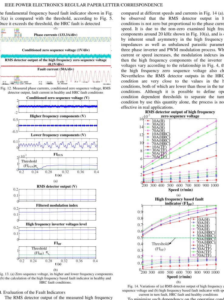
3-phase sets is largely reduced. Also, the degradation or failure on one 3-phase winding and the heat generated by the fault are not likely to transmit to the other phase windings. Each phase winding set ABC, DEF, and GHI forms a balanced 3-phase system in space and time, and is controlled independently by three separate inverters in the same way as a 3-phase IPM machine. Such physical, thermal and electrical isolation guarantees the fault tolerant capability when a fault occurs in one 3-phase winding set and a mitigation action is taken, while the other two 3-phase winding sets are still operational to provide the torque. The test rig set up is shown in Fig. 7. According to [31], the 3-phase system is more unbalanced, and the conventional fault signatures such as 3rd harmonic of phase current, and 2nd harmonic of dq voltages, are higher when more turns are faulted. Therefore, the detection of one single turn short-circuit fault is challenging and addressed in this paper. A single turn short-circuit fault in coil B2 of the 3-phase winding set ABC and a 0.1 HRC fault in phase A are emulated by controlling a relay separately. Due to the current limit of the relay and the additional resistor, all the fault detection tests are conducted below 1000 rpm and 70A for the sake of safety. The current that flows through the shorted turn in turn fault conditions and the current that flows through the additional resistor in the HRC conditions are captured as the fault current to mark the occurrence of the corresponding faults.
The phase winding neutral point is led out and a resistor network is employed to create the artificial neutral point, so that the zero sequence voltage can be measured. An analogue circuit board is designed and constructed for measurement and signal conditioning. Analogue bandpass filters (BPF) are designed to extract the high frequency components around 20 kHz from the measured and conditioned zero sequence voltage. Their RMS value is obtained through the precision wide bandwidth, RMS-to-dc converter LTC1968 from Linear Technology, as has been described in [27]. To separate the lower frequency components from the switching harmonics, the lowpass filters (LPF) are also designed. As only the significance of the fundamental component is to be concerned, and since its frequency is much lower than the fixed switching frequency, the design of the lowpass filter can be very straightforward. The outputs of the analogue circuit board are the zero sequence voltage and the RMS value of the high frequency components around 20 kHz, which are captured and recorded by a multichannel YOKOGAWA oscilloscope. The sampling frequency of the oscilloscope is 500 kHz, in order to analyze the spectrum of the zero sequence voltage, as well as its high and low frequency components with digital filters. The lower frequency components after the analogue LPFs and the RMS value of the high frequency components are also sampled by a Xilinx Zynq-7000 evaluation board. The sampling frequency is 10k Hz, which is the same as the switching frequency of the inverter. The fundamental component can be obtained by the Fourier based frequency components extraction technique. With vd, vq, id, iq available from the controller, the calculation of the fault indicators shown in (15) and (20) can be conducted in the Zynq
processor. Subsequently, the fault detection and classification is realized according to Fig. 5. The flow chart of signal measuring, conditioning, sampling and processing in the designed analogue circuit board and Xilinx Zynq-7000 board is illustrated in Fig. 8.
Table II Machine specifications
Specification Symbol Value
Base speed nb 4000 rpm
Maximum speed nm 19200 rpm
Rated power Pr 35 kW
Rated current Irated 120 A peak
Nominal DC link voltage Vdc 270 V
Turn number of each coil N 8
Number of faulted turns Nf 1
PM flux linkage pm 0.025 Wb
Phase resistance Rs 0.025
d-axis inductance (nominal) Ld 0.38 mH q-axis inductance (nominal) Lq 1.02 mH
Fig. 6. Triple redundant PMA SynRM with segregated windings
Fig. 7. The 9-phase PMA SynRM test rig and DSP controlled 9-phase inverter
LPF BPF RMS detector Fundamenta l extraction (16) (20) umn ia_FUN vd, vq mi (15) id, iq Fault detection & classification
Analogue circuit board Xilinx Zynq-7000 board
umn_HF RMS(umn_HF) FIHF FIFUN umn_FUN RMS(uinverter_HF)
Fig. 8. Flow chart of signal processing for the proposed fault detection and classification
A. Fault Detection and Classification
When a single turn fault occurs at the maximum torque per Ampere (MTPA) operating condition of 1000rpm with 50A phase current, the measurement results are shown in Fig. 9, where the peak fault current can reach 160A. The distortion on the three phase current due to the fault is hardly seen thanks to the PI regulated current control. The fundamental component emerges instantly in the measured zero sequence voltage when the turn fault occurs. However, the increase of the examined high frequency zero sequence voltage components is not so
DSP based 9 phase inverter 9 phase fault tolerant
obvious in the waveform due to the presence of a large number of high frequency components.
Phase currents (133.3A/div)
Conditioned zero sequence voltage (1V/div)
RMS detector output of the high frequency zero sequence voltage (0.1V/div)
Fault current (500A/div) 50ms
Fig. 9. Measured phase currents, conditioned zero sequence voltage, RMS detector output, fault current in healthy and turn fault conditions The spectrum of the zero sequence voltage in the healthy and fault conditions are obtained through FFT analysis and shown in Fig. 10(a) and (b) respectively. It is clear that the switching sideband harmonics around 20 kHz which are extracted through the BPFs in this method stay low in healthy condition, but exhibit prominent increase when the turn fault occurs. By applying the same transfer function of the bandpass filter in the analogue circuit to the measured zero sequence voltage, the switching sideband harmonics around 20 kHz are separated, shown in Fig. 11(a). It is evident that their magnitudes are low in the healthy condition, but rise significantly in the turn fault condition. Correspondingly, the measured RMS detector output of the high frequency components in Fig. 9 also increases largely. The lower frequency components can also be analysed through a low pass filter. It shows that the fundamental frequency component is hardly seen in the healthy condition, where only 3rd and higher order harmonics exist, but increases when the turn fault occurs. The calculation of the high frequency fault indicator in the processor is shown in Fig. 11(b). The RMS detector output is directly measured from the analogue circuit signal conditioning board. The command voltage vd and vq from the controller are sent to the Zynq processor to obtain the modulation index, which can be filtered digitally with the same transfer function of the low pass filter in the RMS detector to synchronise their response. Then by applying the 5-order polynomial shown in (16) to estimate the high frequency components of the inverter outputs. Finally, the high frequency based fault indicator is obtained. According to Fig. 5, by comparing this fault indicator with the predefined threshold, the turn fault can be detected directly.
0 0.5 1 1.5 2 2.5 Frequency/Hz 105 0 1 2 3 4 M agni tude
Spectrum of zero sequence voltage in healthy condition Extracted frequency components 0 0.5 1 1.5 2 2.5 Frequency/Hz 105 0 1 2 3 4
Spectrum of zero sequence voltage in turn fault condition
Extracted frequency components M agni tude (a) (b)
Fig. 10. Spectrum of zero sequence voltage in (a) healthy and (b) turn fault conditions
-2 0
2 Conditioned zero sequence voltage (V)
-0.5 0
0.5 Higher frequency components (V)
0 0.1
Lower frequency components (V)
0.2 0.24 0.28 0.32 0.36 0.4 0 1 2 10-3 FIFUN t (s) (a) 0 0.1 0.2 RMS detector output (V) 0 0.1 0.2
Filtered modulation index
0 0.1
0.2 High frequency inverter voltages level
0.2 0.24 0.28 0.32 0.36 0.4 0 1 FIHF t (s) Threshold (FIHF) (b)
Fig. 11. (a) Zero sequence voltage, its higher and lower frequency components (b) the calculation of the high frequency based fault indicator in healthy and
turn fault conditions.
Under the same operating condition, a 0.1 additional
resistor formed HRC fault is activated, and the measurement results are shown in Fig. 12. To indicate the onset of the HRC fault, the current flowing through the resistor is also measured
denoted as the “fault current”. To illustrate the key features in
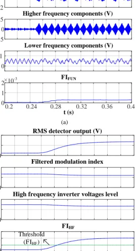
the zero sequence voltage, the frequency components under evaluation are also examined through high and low pass filtering, shown in Fig. 13(a). As can be observed, the filtered high frequency component is very low and does not increase in the HRC fault condition. As the result, the directly measured RMS detector output for the switching sideband harmonics around 20 kHz shown in Fig. 12 also has very little change. The high frequency based fault indicator is calculated in Fig. 13(b) after the modulation index is obtained. Comparing with the result in the turn fault condition, the high frequency components in the zero sequence voltage are much more sensitive to the turn fault, thus the high frequency based fault indicator can be employed for the exclusive turn fault detection. As the detection result of the turn fault is negative,
the fundamental frequency based fault indicator shown in Fig. 13(a) is compared with the threshold, according to Fig. 5. Once it exceeds the threshold, the HRC fault is detected
Phase currents (133.3A/div)
Conditioned zero sequence voltage (1V/div)
RMS detector output of the high frequency zero sequence voltage (0.1V/div)
Fault current (50A/div)
Fig. 12. Measured phase currents, conditioned zero sequence voltage, RMS detector output, fault current in healthy and HRC fault conditions
-2 0
2 Conditioned zero sequence voltage (V)
-0.5 0 0.5
Higher frequency components (V)
0 0.1
Lower frequency components (V)
0.2 0.24 0.28 0.32 0.36 0.4 0 1 2 10-3 FIFUN t (s) Threshold (FIFUN) (a) 0 0.1 0.2 RMS detector output (V) 0 0.1
0.2 Filtered modulation index
0 0.1
0.2 High frequency inverter voltages level
0.2 0.24 0.28 0.32 0.36 0.4 0 1 FIHF t (s) Threshold (FIHF) (b)
Fig. 13. (a) Zero sequence voltage, its higher and lower frequency components (b) the calculation of the high frequency based fault indicator in healthy and
HRC fault conditions. B. Evaluation of the Fault Indicators
The RMS detector output of the measured high frequency zero sequence voltage in the healthy, turn fault and HRC fault
conditions, denoted as ‘H’, ‘TF’, and ‘HRC’ respectively, are
compared at different speeds and currents in Fig. 14 (a). It can be observed that the RMS detector output in healthy conditions is not zero but proportional to the phase current and speed. It is due to the non-zero examined high frequency components around 20 kHz shown in Fig. 10(a), and is caused by inherent small asymmetry in the high frequency phase impedances as well as unbalanced parasitic parameters in three phase inverter and PWM modulation process. When the current or speed increases, the modulation indexes increase, then the high frequency components of the inverter output voltages vary according to the relationship in Fig. 4, thereby, the high frequency zero sequence voltage also changes. Nevertheless the RMS detector outputs in the HRC fault condition are very close to the values in the healthy conditions, both of which are lower than those in the turn fault conditions. Although it is possible to define operating condition dependent thresholds to separate the turn fault condition by use this quantity alone, the process is not cost-effective in real applications.
200 300 400 500 600 700 800 900 1000 0 2 4 6 8 10 12 14 16
RMS detector output of high frequency zero sequence voltage
10A(H) 30A(H) 50A(H) 70A(H) 10A(HRC) 30A(HRC) 50A(HRC) 70A(HRC) 10A(TF) 30A(TF) 50A(TF) 70A(TF) Speed (r/min) 10-2 (a) 200 300 400 500 600 700 800 900 1000 0 0.1 0.2 0.3 0.4 0.5 0.6 0.7 0.8 0.9 1
High frequency based fault indicator (FIHF) 10A(H) 30A(H) 50A(H) 70A(H) 10A(HRC) 30A(HRC) 50A(HRC) 70A(HRC) 10A(TF) 30A(TF) 50A(TF) 70A(TF) Speed (r/min) Threshold (FIHF) (b)
Fig. 14. Variations of (a) RMS detector output of high frequency zero sequence voltage and (b) high frequency based fault indicator with speed and
current in turn fault, HRC fault and healthy conditions
To minimize such dependency on the operating conditions, the high frequency based fault indicator expressed in (15) is obtained, and compared for the healthy, turn fault and HRC
conditions in Fig. 14(b). It can be observed that the variation of the fault indicator in healthy and HRC conditions due to speed and current has been reduced effectively, especially at higher current and speed conditions. The more deviations of the indicator at lower speed and current conditions can be attributed to the lower magnitude of the high frequency components at lower modulation indexes, which makes the measurement more sensitive to the noise. For the turn fault conditions, although the dependence of the fault indicator on the speed and current still remains, a significant difference of the fault indicators is seen between turn fault and other conditions, where the smallest difference lies at the lower speed. Based on these experimental observations, the threshold for the exclusive detection of turn fault can be determined in a convenient manner. It can be selected as a constant value, and the detectability of the turn fault at low speeds is improved. 200 300 400 500 600 700 800 900 1000 0 0.5 1 1.5 2 2.5 3 3.5 4 4.5 5
Fundamental component magnitude of conditioned zero sequence voltage
Speed (r/min) (a) 200 300 400 500 600 700 800 900 1000 0 1 2 3 4 5 6 7 8 9 10-4
Fundamental component based fault indicator (FIFUN)
10A(H) 30A(H) 50A(H) 70A(H) 10A(HRC) 30A(HRC) 50A(HRC) 70A(HRC) Speed (r/min) Threshold (FIFUN) (b)
Fig. 15. Variations of (a) fundamental component of zero sequence voltage (b) fundamental frequency based fault indicator with speed and current in HRC
fault and healthy conditions
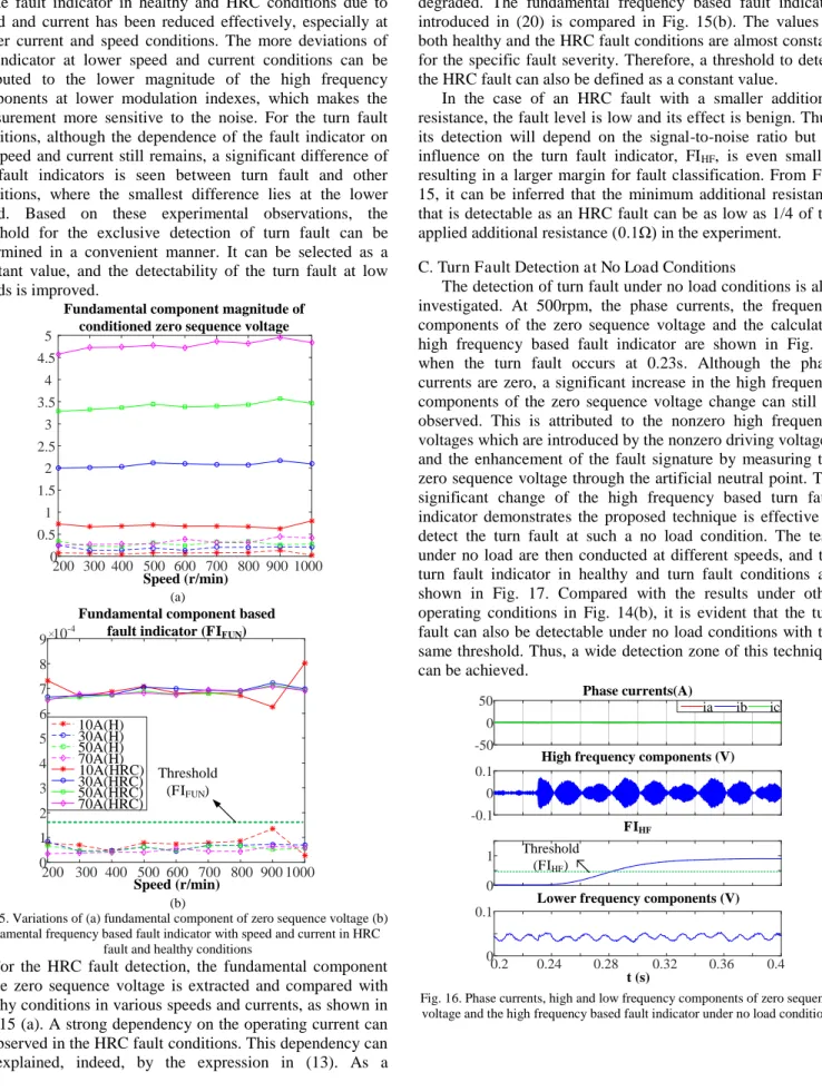
For the HRC fault detection, the fundamental component of the zero sequence voltage is extracted and compared with healthy conditions in various speeds and currents, as shown in Fig. 15 (a). A strong dependency on the operating current can be observed in the HRC fault conditions. This dependency can be explained, indeed, by the expression in (13). As a
consequence, the detectability under lower current is degraded. The fundamental frequency based fault indicator introduced in (20) is compared in Fig. 15(b). The values in both healthy and the HRC fault conditions are almost constant for the specific fault severity. Therefore, a threshold to detect the HRC fault can also be defined as a constant value.
In the case of an HRC fault with a smaller additional resistance, the fault level is low and its effect is benign. Thus, its detection will depend on the signal-to-noise ratio but its influence on the turn fault indicator, FIHF, is even smaller, resulting in a larger margin for fault classification. From Fig. 15, it can be inferred that the minimum additional resistance that is detectable as an HRC fault can be as low as 1/4 of the applied additional resistance (0.1 ) in the experiment.
C. Turn Fault Detection at No Load Conditions
The detection of turn fault under no load conditions is also investigated. At 500rpm, the phase currents, the frequency components of the zero sequence voltage and the calculated high frequency based fault indicator are shown in Fig. 16 when the turn fault occurs at 0.23s. Although the phase currents are zero, a significant increase in the high frequency components of the zero sequence voltage change can still be observed. This is attributed to the nonzero high frequency voltages which are introduced by the nonzero driving voltages, and the enhancement of the fault signature by measuring the zero sequence voltage through the artificial neutral point. The significant change of the high frequency based turn fault indicator demonstrates the proposed technique is effective to detect the turn fault at such a no load condition. The tests under no load are then conducted at different speeds, and the turn fault indicator in healthy and turn fault conditions are shown in Fig. 17. Compared with the results under other operating conditions in Fig. 14(b), it is evident that the turn fault can also be detectable under no load conditions with the same threshold. Thus, a wide detection zone of this technique can be achieved. -50 0 50 Phase currents(A) ia ib ic -0.1 0 0.1
High frequency components (V)
0 1 FIHF 0.2 0.24 0.28 0.32 0.36 0.4 0 0.1
Lower frequency components (V)
t (s)
Threshold (FIHF)
Fig. 16. Phase currents, high and low frequency components of zero sequence voltage and the high frequency based fault indicator under no load conditions
200 300 400 500 600 700 800 900 1000 0 0.1 0.2 0.3 0.4 0.5 0.6 0.7 0.8 0.9
1 High frequency based fault indicator at 0A
(H) (TF)
Speed (r/min)
Threshold (FIHF)
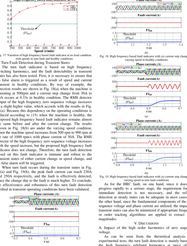
Fig. 17. Variation of high frequency based fault indicator at no load condition with speeds in turn fault and healthy conditions
D. Turn Fault Detection during Transient States
The turn fault indicator is based on high frequency switching harmonics, and the fault detectability in transient states has also been tested. First, it is necessary to ensure that no false alarm is triggered as a result of speed and current transient in healthy conditions. By way of example, the detection results are shown in Fig. 18(a) when the machine is operating at 500rpm and a current step change from 30A to 70A occurs at 0.33s in healthy condition. The RMS detector output of the high frequency zero sequence voltage increases to a slight higher value, which accords with the results in Fig. 14(a). Because this dependency on the operating conditions is reduced according to (15) when the machine is healthy, the proposed high frequency based fault indicator remains almost the same before and after the current change. The results shown in Fig. 18(b) are under the varying speed condition, when the machine speed increases from 500 rpm to 900 rpm at the rate of 1000 rpm/s with phase current of 50A. The RMS detector of the high frequency zero sequence voltage increases with the speed increase, but the proposed high frequency fault indicator does not change. Therefore, the turn fault detection based on this fault indicator is immune and robust to the transient states of either current change or speed change, and no false alarm will be triggered.
When turn fault occurs during the transient states in Fig. 19(a) and Fig. 19(b), the peak fault current can reach 230A and 250A respectively, and the fault is effectively detected, since the change due to the fault is much higher. To conclude, the effectiveness and robustness of this turn fault detection method in transient operating conditions have been validated.
-100 0 100
Phase currents (A)
ia ib ic -500 0 500 Fault current(A) 0.3 0.4 0.5 0.6 0.7 0 0.5 1 1.5 FIHF t (s) Threshold (FIHF) (a) -100 0 100
Phase currents (A)
ia ib ic -500 0 500 Fault current(A) 1 1.1 1.2 1.3 1.4 0 0.5 1 1.5 FIHF t (s) Threshold (FIHF) (b)
Fig. 18. High frequency based fault indicator with (a) current step change (b) varying speed in healthy conditions
-100 0 100
Phase currents (A)
ia ib ic -500 0 500 Fault current(A) 0.3 0.4 0.5 0.6 0.7 0 0.5 1 1.5 FIHF t (s) Threshold (FIHF) (a) -100 0 100
Phase currents (A)
ia ib ic -500 0 500 Fault current(A) 0.8 0.9 1 1.1 1.2 0 0.5 1 1.5 FIHF t (s) Threshold (FIHF) (b)
Fig. 19. High frequency based fault indicator with (a) current step change (b) varying speed in turn fault conditions
As for the HRC fault, on one hand, since it does not progress rapidly to a serious stage, the requirement for the immediate detection is not necessary, and the reliable detection at steady states can be adequate in most cases. On the other hand, since the fundamental components of the zero sequence voltage and phase current are utilized, the impact of transient states can also be minimized if appropriate frequency or order tracking algorithms are applied to extract their magnitudes.
V.DISCUSSIONS
A. Impact of the high order harmonics of zero sequence voltage.
As can be seen from the theoretical analysis and experimental tests, the turn fault detection is mainly based on the high frequency sideband harmonics at twice of the
switching frequency of the zero sequence voltages. The tested machine is fed with 10 kHz PWM voltages, and the examined high frequency components are around 20 kHz. The remaining higher order harmonics of the zero sequence voltage caused by distortion in back-emf and the slotting effect are odd integer multiples of its 3rd harmonics, with the amplitudes decreasing as the frequency increases. Compared with the influence of the inherent asymmetries shown in Fig. 10(a) on the switching sideband harmonics, the impact of the high order harmonics of the zero sequence voltage can be ignored. Thus this method normally does not introduce additional limit on the applicable fundamental-to-switching frequency ratio, as long as appropriate PWM modulation is applied.
B. Comparison with existing classification methods
The main problems of the existing classification methods [25][26], namely, sensitive to machine parameter variations and inability to cope with transient states, have been discussed in section I. However, these problems can be solved by the proposed method.
The classification method of turn fault and HRC fault proposed in this paper is based on the characteristic difference of inductive and resistive impedance at high frequency which can be approximated by (18) and (19) with given parameters. Although the parameters may be inaccurate and the initial inherent asymmetry may exist, the test results have demonstrated the significant difference of FIHF in the two fault conditions. Thus, this method is more robust against machine parameter variations, and its implementation is more straightforward.
As there is no FFT calculation and the signals are processed by analogue filters, the fault indicators approach gradually to new steady state values when transient states occur. According to Fig. 14, the steady state values in healthy conditions do not vary much with speed or current, compared to the change with turn fault, thus the thresholds can be determined in a convenient and with robust manner against transient states.
The use of the filters, especially the low pass filter in the RMS detector does compromise response time of the turn fault detection. However, from the test results, turn fault can always be detected within 0.1s, which is much shorter than the time constant of hot spot temperature increase in the worst case turn fault condition. .
Since most existing classification methods rely on the phase currents, their performances are largely degraded at no load conditions when the phase currents are very low. Consequently, detection of turn fault is no longer reliable. However, the turn fault detection in the proposed method is based on the switching harmonic components which are still very significant under on load. Thus, zero or low phase current in no load conditions does not impair the turn fault detection, as has been demonstrated in Fig. 16 and Fig. 17.
C. Extra resistor bank and voltage measurement
In order to implement this technique, an extra resistor bank for creating the artificial neutral point is needed. The resistor can have a low power rating with high resistance (50 k , 1 W in this test rig). It can also be integrated in the inverter.
In addition, the phase neutral point needs to be accessible, which might not be applicable in some scenarios. The phase neutral point is only for the measurement of the zero sequence voltage and does not introduce neutral current.
The measured zero sequence voltage reflects the machine’s behaviour and hence the influences of the inverter and control algorithm on fault signatures are eliminated. Consequently, the sensitivity to winding fault detection is largely improved, which contributes to the robustness of the fault detection.
VI.CONCLUSIONS
This paper has proposed a turn fault and HRC fault detection and classification technique based on both the high and fundamental frequency components of the zero sequence voltage. Although the phase neutral point needs to be accessible and the extra resistor network needs to be built for the measurement of zero sequence voltage, the detection sensitivity to the faults can be enhanced. The fault indicator is proposed to minimize the impact of the operating conditions, and facilitate a convenient determination of the thresholds. A complete fault detection and classification procedure has been developed. The effectiveness is validated through extensive experimental tests. The turn fault detection in no load conditions and transient states are also tested, with the robustness of this technique being demonstrated.
REFERENCES
[1] W. Cao, B. C. Mecrow, G. J. Atkinson, J. W. Bennett, and D. J.
Atkinson, “Overview of electric motor technologies used for more electric aircraft (MEA),” IEEE Trans. Ind. Electron., vol. 59, no. 9, pp. 3523–3531, 2012.
[2] Z. Q. Zhu and D. Howe, “Electrical Machines and Drives for
Electric, Hybrid, and Fuel Cell Vehicles,” Proc. IEEE, vol. 95, no. 4, pp. 746–765, 2007.
[3] G. Vachtsevanos, F. Lewis, A. Hess, and B. Wu, Intelligent fault diagnosis and prognosis for engineering systems. Hoboken: Wiley, 2006.
[4] IEEE, “Report of Large Motor Reliability Survey of Industrial and
Commercial Installations, Part I,” IEEE Trans. Ind. Appl., vol. IA-21, no. 4, pp. 853–864, 1985.
[5] B. M. Ebrahimi and J. Faiz, “Feature Extraction for Short-Circuit Fault Detection in Permanent-Magnet Synchronous Motors Using Stator-Current Monitoring,” IEEE Trans. Power Electron., vol. 25, no. 10, pp. 2673–2682, 2010.
[6] G. M. Joksimovic and J. Penman, “The detection of inter-turn short
circuits in the stator windings of operating motors,” IEEE Trans. Ind. Electron., vol. 47, no. 5, pp. 1078–1084, 2000.
[7] K.-H. Kim, D.-U. Choi, B.-G. Gu, and I.-S. Jung, “Online fault -detecting scheme of an inverter-fed permanent magnet synchronous motor under stator winding shorted turn and inverter switch open,” IET Electr. Power Appl., vol. 4, no. 4, p. 214, 2010.
[8] Y. Mollet, X. Kestelyn, F. Meinguet, E. Semail, and J. Gyselinck,
“Change-detection algorithm for short-circuit fault detection in closed-loop AC drives,” IET Electr. Power Appl., vol. 8, no. 5, pp. 165–177, 2014.
[9] H. Jeong, S. Moon, and S. W. Kim, “An Early Stage Interturn Fault Diagnosis of PMSMs by Using Negative-Sequence Components,” IEEE Trans. Ind. Electron., vol. 64, no. 7, pp. 5701–5708, 2017. [10] R. M. Tallam, T. G. Habetler, and R. G. Harley, “Stator winding
turn-fault detection for closed-loop induction motor drives,” IEEE Trans. Ind. Appl., vol. 39, no. 3, pp. 720–724, 2003.
[11] J. C. Urresty, J. R. Riba, and L. Romeral, “Diagnosis of interturn faults in pmsms operating under nonstationary conditions by
applying order tracking filtering,” IEEE Trans. Power Electron., vol. 28, no. 1, pp. 507–515, 2013.
Diagnosis of Permanent Magnet Synchronous Machine Using Zero
Sequence Components,” IEEE Trans. Power Electron., vol. 30, no. 12, pp. 6731–6741, 2015.
[13] R. D. Naybour and T. Farrell, “Degradation mechanisms of
mechanical connectors on aluminium conductors,” Proc. Inst. Electr. Eng., vol. 120, no. 2, pp. 273–280, 1973.
[14] M. Braunovic, “Effect of Connection Design on the Contact
Resistance of High Power Overlapping Bolted Joints,” IEEE Trans. Components Packag. Technol., vol. 25, no. 4, pp. 642–650, 2002. [15] J. Yun, J. Cho, S. Bin Lee, and J. Y. Yoo, “Online detection of
high-resistance connections in the incoming electrical circuit for
induction motors,” IEEE Trans. Ind. Appl., vol. 45, no. 2, pp. 694– 702, 2009.
[16] P. M. De La Barrera, G. R. Bossio, and J. A. Solsona, “High -resistance connection detection in induction motor drives using
signal injection,” IEEE Trans. Ind. Electron., vol. 61, no. 7, pp. 3563–3573, 2014.
[17] P. M. De Barrera, G. R. Bossio, and R. Leidhold, “On Line Voltage Sensorless High-Resistance Connection Diagnosis in Induction Motor Drives,” IEEE Trans. Ind. Electron., vol. 62, no. 7, pp. 4374– 4384, 2015.
[18] M. Mengoni, L. Zarri, A. Tani, Y. Gritli, G. Serra, F. Filippetti, and
D. Casadei, “Online Detection of High-Resistance Connections in
Multiphase Induction Machines,” IEEE Trans. Power Electron., vol. 30, no. 8, pp. 4505–4513, 2015.
[19] L. Zarri, M. Mengoni, Y. Gritli, A. Tani, F. Filippetti, G. Serra, and
D. Casadei, “Detection and localization of stator resistance
dissymmetry based on multiple reference frame controllers in multiphase induction motor drives,” IEEE Trans. Ind. Electron., vol. 60, no. 8, pp. 3506–3518, 2013.
[20] J. Hang, J. Zhang, S. Ding, and M. Cheng, “Fault Diagnosis of High-Resistance Connection in a Machine Considering the
Neutral-Point Connection Model,” IEEE Trans. Power Electron., vol. 32, no. 8, pp. 6444–6454, 2017.
[21] J. Zhang, J. Hang, S. Ding, and M. Cheng, “Online Diagnosis and Localization of High-Resistance Connection in PMSM With
Improved Fault Indicator,” IEEE Trans. Power Electron., vol. 32, no. 5, pp. 3585–3594, 2017.
[22] J. U. J. Riba, L. Romeral, and J. Antonio, “Mixed resistive unbalance and winding inter-turn faults model of permanent magnet
synchronous motors,” Electr. Eng., no. 97, pp. 75–85, 2015. [23] R. Roshanfekr and A. Jalilian, “Wavelet-based index to discriminate
between minor inter-turn short-circuit and resistive asymmetrical
faults in stator windings of doubly fed induction generators : a simulation study,” IET Gener. Transm. Distrib., vol. 10, no. 2, pp. 374–381, 2016.
[24] J. Yun, S. Member, J. Cho, S. Member, S. Bin Lee, S. Member, and
J. Yoo, “Online Detection of High-Resistance Connections in the
Incoming Electrical Circuit for Induction Motors,” IEEE Trans. Ind. Appl., vol. 45, no. 2, pp. 694–702, 2009.
[25] J. Yun, K. Lee, K. W. Lee, S. Bin Lee, and J. Y. Yoo, “Detection and classification of stator turn faults and high-resistance electrical
connections for induction machines,” IEEE Trans. Ind. Appl., vol. 45, no. 2, pp. 666–675, 2009.
[26] B. Sen, “Modelling , Fault Detection and Control of Fault Tolerant
Permanent Magnet Machine Drives,” PhD thesis, Univ. Sheff., no. September, 2015.
[27] R. Hu, J. Wang, B. Sen, A. R. Mills, E. Chong, and Z. Sun, “PWM Ripple Currents Based Turn Fault Detection for Multiphase
Permanent Magnet Machines,” IEEE Trans. Ind. Appl., vol. 53, no. 3, pp. 2740–2751, 2017.
[28] B. Vaseghi, B. Nahid-Mobarakh, N. Takorabet, and F.
Meibody-Tabar, “Inductance identification and study of PM motor with winding turn short circuit fault,” IEEE Trans. Magn., vol. 47, no. 5, pp. 978–981, 2011.
[29] R. Hu, J. Wang, A. R. Mills, E. Chong, and Z. Sun, “PWM Ripple Currents Based Turn Fault Detection for 3-phase Permanent Magnet
Machines,” IEEE Int. Electr. Mach. Drives Conf., pp. 1–7, 2017. [30] B. Wang, J. Wang, B. Sen, A. Griffo, Z. Sun, and E. Chong, “A
Fault-Tolerant Machine Drive Based on Permanent
Magnet-Assisted Synchronous Reluctance Machine,” IEEE Trans. Ind. Appl., vol. 54, no. 2, pp. 1349–1359, 2018.
[31] M. Zafarani, E. Bostanci, Y. Qi, T. Goktas, and B. Akin, “Inter-turn Short Circuit Faults in Permanent Magnet Synchronous Machines :
An Extended Review and Comprehensive Analysis,” IEEE J. Emerg. Sel. Top. Power Electron., vol. 6, no. 4, pp. 2173–2191, 2018.
Rongguang Hu (S’16) received B.Eng. degree and M.Sc. degree in electrical engineering from Nanjing University of Aeronautics and Astronautics, Nanjing, China, in 2012 and 2015, respectively.
He is currently pursuing the Ph.D. degree in electrical machines and drives research group at the University of Sheffield, U.K. His research interests include power-electronic control of electric machines, sensorless control and fault diagnosis.
Jiabin Wang (SM’03) received the B.Eng. and M.Eng. degrees from Jiangsu University of Science and Technology, Zhenjiang, China, in 1982 and 1986, respectively, and the Ph.D. degree from the University of East London, London, U.K., in 1996, all in electrical and electronic engineering.
Currently, he is a Professor in Electrical Engineering at the University of Sheffield, U.K. He was a Postdoctoral Research Associate at the University of Sheffield, U.K., from 1996 to 1997, and a Senior Lecturer at the University of East London from 1998 to 2001. His research interests range from motion control and electromechanical energy conversion to electric drives for applications in automotive, renewable energy, household appliances and aerospace sectors. He is a fellow of the IET and a senior member of IEEE.
Andrew R Mills, CEng, PhD, is a Senior Researcher and Research Programme Manager at the University of Sheffield. He has worked in the defense industry on aerospace and automotive applications before his current post within the University Technology Centre supported by Rolls-Royce. Research interests are in the application of control systems engineering principles to a broad range of applied control and health management research challenges.
Ellis Chong, PhD, CEng, MIET, received his PhD degree in electrical engineering from the University of Cambridge in 2001. He is a chartered electrical engineer and has been working in the transport and power industries in the areas of electrical machines and power electronics since 2001. He is currently the Electrical Machines and Power Electronics Team Leader in the Electrical Capability Group in Rolls-Royce Plc.
Zhigang Sun received his PhD degree in Electrical Engineering from the University of Sheffield in 2009. He has been working in the field of electrical power systems in various professional roles in aerospace industry, semiconductor industry and higher education since 2009. He is currently an Electrical Engineer at Electrical Capability Group at Rolls-Royce plc.