USING SURFACE-WAVE COMMUNICATION
Ammar J. M. Karkar
A Thesis Submitted for the Degree of Doctor of Philosophy at Newcastle University School of Electrical and Electronic Engineering Faculty of Science, Agriculture and Engineering
I hereby declare that this thesis is my own work and effort and that it has not been submitted anywhere for any award. Where other sources of information have been used, they have been acknowledged. Newcastle upon Tyne, August2016
I confirm that, to the best of my knowledge, this thesis is from the student’s own work and effort, and all other sources of information used have been acknowledged. This thesis has been submitted with my approval.
I would like to express my sincere gratitude to my supervisors Prof. Alex Yakovlev and Prof. Terrence Mak for their support and guidance through my studies. They have been and always will be a source of inspiration and my role model as a researcher.
I am also grateful to my colleagues and friends in the School of Elec-trical and Electonic Engineering, especially those in Microelectronic Systems research group, at Newcastle University for their assistance and guidance in my studies. Especially, I appreciate the support of my wonderful friends and colleagues Dr. Nizar Dahir, Dr. Ra’ed Aldujaily, Dr. Ahmed Sabaawi, Dr. Walled Amer and Dr. Hussein Leftah for fruitful discussions, productive suggestions, and subjective criticism. In addition, I would like to thank Dr. Graeme Coapes for his help and advice regarding the building of the SNN benchmark.
I would also wish to thank Prof. Kin-Fai Tong and Dr. Janice Turner for their help in offering their experiment results and knowledge, which assist me toward the understanding of Zennek surface wave.
I am also thankful for Dr. Xiaohang Wang for his assistance in building application benchmarks.
I am also grateful to Dr Maurizio Palesi for his advice in modifying the NoC simulator to include the feature of simulating the VCs.
Finally, I would like to offer my special regards to all the staff of the school of Electrical and Electronic Engineering in Newcastle university.
Networks-on-chip (NoCs) is a communication paradigm that has emerged aiming to address on-chip communication challenges and to satisfy interconnection demands for chip-multiprocessors (CMPs). Nonetheless, there is continuous demand for even higher computa-tional power, which is leading to a relentless downscaling of CMOS technology to enable the integration of many-cores. However, technol-ogy downscaling is in favour of the gate nodes over wires in terms of latency and power consumption. Consequently, this has led to the era of many-core processors where power consumption and perfor-mance are governed by inter-core communications rather than core computation. Therefore, NoCs need to evolve from being merely metal-based implementations which threaten to be a performance and power bottleneck for many-core efficiency and scalability.
To overcome such intensified inter-core communication challenges, this thesis proposes a novel interconnect technology: the surface-wave interconnect (SWI). This new RF-based on-chip interconnect has no-table characteristics compared to cutting-edge on-chip interconnects in terms of CMOS compatibility, high speed signal propagation, low power dissipation, and massive signal fan-out. Nonetheless, the realiza-tion of the SWI requires investigarealiza-tions at different levels of abstracrealiza-tion, such as the device integration and RF engineering levels. The aim of this thesis is to address the networking and system level chal-lenges and highlight the potential of this interconnect. This should encourage further research at other levels of abstraction. Two specific system-level challenges crucial in future many-core systems are tack-led in this study, which are cross-the-chip global communication and one-to-many communication.
This thesis makes four major contributions towards this aim. The first is reducing the NoC average-hop count, which would otherwise increase packet-latency exponentially, by proposing a novel hybrid interconnect architecture. This hybrid architecture can not only uti-lize both regular metal-wire and SWI, but also exploits merits of both bus and NoC architectures in terms of connectivity compared to other general-purpose on-chip interconnect architectures. The second contribution addresses global communication issues by developing a distance-based weighted-round-robin arbitration (DWA) algorithm. This technique prioritizes global communication to be send via SWI short-cuts, which offer more efficient power dissipation and faster across-the-chip signal propagation. Results obtained using a cycle-accurate simulator demonstrate the effectiveness of the proposed system architecture in terms of significant power reduction,
cations, which are normally associated with traffic overload, hotspots and deadlocks and therefore increase, by an order of magnitude the power consumption and latency. This has been achieved by propos-ing a novel routpropos-ing and centralized arbitration schemes that exploits the SWI0s remarkable fan-out features. The evaluation demonstrates drastic improvements in the effectiveness of the proposed architecture in terms of power consumption (2-10x) and performance (22x) but with negligible hardware overheads (2%). The fourth contribution is to further explore multicast contention handling in a flexible decen-tralized manner, where original techniques such as stretch-multicast and ID-tagging flow control have been developed. A comparison of these techniques shows that the decentralized approach is superior to the centralized approach with low traffic loads, while the latter outperforms the former near and after NoC saturation.
Journal and magazines publications:
1. Ammar J. M. Karkar; Janice E. Turner; Kenneth Tong; Ra’ed AI-Dujaily; Terrence Mak ; Alex Yakovlev; Fei Xia,Hybrid wire-surface wave interconnects for next-generation networks-on-chip, IET Computers and Digital Techniques,2013,7, (6), p.294-303, DOI: 10.1049/iet-cdt.2013.0030, IET Digital Library.
2. Ammar J. M. Karkar; Terrence Mak; N. Dahir ; Ra’ed AI-Dujaily; Kenneth Tong; Alex Yakovlev;Network-on-Chip Multicast Architec-tures Using Hybrid Wire and Surface-Wave Interconnects,2016, IEEE Transactions on Emerging topics in Computing, special issue on Emerging Computational paradigms and Architectures for Multi-core Platforms. ISSN2168-6750. doi:10.1109/TETC.2016.2551043 3. Ammar J. M. Karkar, T. Mak, K. Tong, and A. Yakovlev, A Survey of Emerging Interconnects for On-chip Efficient Multicast and Broadcast in Many-cores, Circuits and Systems Magazine, IEEE, 16(1):58-72, Firstquarter2016. ISSN1531-636X. doi:10.1109 /M-CAS.2015.2510199.
Conference publications:
1. Ammar J. M. Karkar; N. Dahir; R. Al-Dujaily; K. Tong; T. Mak ; A. Yakovlev ,Hybrid wire-surface wave architecture for one-to-many communication in networks-on-chip, Design, Automation and Test in Europe Conference and Exhibition (DATE),2014, pp.1,4,24-28 March2014, doi:10.7873/DATE.2014.287
2. Ammar J. M. Karkar, K. Tong, T. Mak, and A. Yakovlev,Mixed wire and surfacewave communication fabrics for decentralized on-chip multicasting, in Design, Automation and Test in Europe Conference and Exhibition (DATE),2015, (EDA Consortium), pp 794-799, March2015. ISBN978-3-9815370-4-8.
Workshop and forum publications:
1. Ammar J. M. Karkar, R. Al-Dujaily, A. Yakovlev, K. Tong, and T. Mak,Surface wave communication system for on-chip and off-chip interconnects, in Proceedings of the Fifth International Workshop
2. Ammar J. M. Karkar, T. Mak and A. Yakovlev, Surface wave communication systems for on-chip and off chip interconnects, Pro-ceedings of UK Electronics Forum (UKEF’12), Newcastle,30-31th Aug.2012, pp.59-64.
I also contributed in the following works:
1. Mengyuan Wu; Ammar J. M. Karkar; Bo Liu; A. Yakovlev; G. Gielen; V. Grout,Network on Chip optimization based on surrogate model assisted evolutionary algorithms, Evolutionary Computation (CEC),2014IEEE Congress on , vol., no., pp.3266,3271,6-11July 2014doi:10.1109/CEC.2014.6900559.
2. B. Liu, F. Fernandez, G. Gielen, Ammar J. M. Karkar, A. Yakovlev, V. Grout, SMAS: A Generalized and Efficient Framework for Com-putationally Expensive Electronic Design Optimization Problems , Computational Intelligence in Analog and Mixed-Signal (AMS) and Radio-Frequency (RF) Circuit Design, Springer,2015 (Ac-cepted).
I Thesis Chapters 1 1 i n t r o d u c t i o n 2 1.1 Motivation . . . 2 1.2 Statement of originality . . . 5 1.3 Thesis Organization . . . 7 2 b a c k g r o u n d a n d l i t e r at u r e r e v i e w 10 2.1 Introduction . . . 10 2.2 Background . . . 10 2.2.1 Networks-on-chip . . . 10
2.2.2 Deadlock, Livelock and Starvation . . . 14
2.2.3 Flow Control . . . 16
2.2.4 Routing Algorithms . . . 19
2.2.5 Arbitration and Allocation . . . 21
2.2.6 Multi/Many-Core Processors . . . 23
2.2.7 Cache Coherence . . . 24
2.2.8 Three-Dimensional Integration . . . 25
2.3 Literature Review . . . 26
2.3.1 Current and Emerging Interconnects . . . 26
2.3.2 Existing NoC Architectures . . . 40
2.3.3 NoC Simulators and Models . . . 42
3 s u r fa c e-wav e o n-c h i p i n t e r c o n n e c t 45 3.1 Introduction . . . 45
3.2 Surface-Wave interconnect fabric . . . 46
3.2.1 Surface Wave Interconnects (SWI) implementation 46 3.2.2 SWI Links design . . . 47
3.2.3 SWI Challenges . . . 49
3.3 Zenneck Surface wave modelling . . . 49
3.3.1 Analysis of link power dissipation . . . 49
3.3.2 Communication system performance . . . 50
3.4 Experiment Results . . . 53
3.5 Summary and Conclusion . . . 55
4 h y b r i d w i r e a n d s u r fa c e-wav e a r c h i t e c t u r e f o r o n -c h i p g l o b a l c o m m u n i c at i o n s 57 4.1 Introduction . . . 57
4.2 Relevant Work on Cross-the-chip Communications . . 58
4.2.1 Multi-hope Challenges and Wire-based Solutions 58 4.2.2 Routing in Hybrid Architectures . . . 58
4.3 Hybrid Wire and Surface-wave Interconnect Architecture 59 4.3.1 Addressing Multi-hop Challenges Using W-SWI
Architecture . . . 59
4.3.2 Routing scheme . . . 62
4.3.3 Distance-based Weighted-round-robin Arbitra-tion (DWA) Algorithm . . . 63
4.4 System level evaluation and discussion . . . 66
4.4.1 Performance Evaluation . . . 68
4.4.2 Power Consumption . . . 70
4.4.3 Area Estimation . . . 71
4.5 Summary and Conclusion . . . 73
5 w i r e a n d s u r fa c e-wav e a r c h i t e c t u r e w i t h c e n t r a l -i z e d c o n t r o l f o r m u lt i c a s t 74 5.1 Introduction and Motivation . . . 74
5.1.1 Motivation . . . 75
5.2 Related Work in Current and Emerging Interconnects for Multicast . . . 77
5.2.1 Wire-based Multicast Routing and Architectures 77 5.2.2 Optical interconnects . . . 79
5.2.3 Wireless Interconnects . . . 80
5.2.4 Transmission Lines . . . 81
5.2.5 SWI Fanout Feature . . . 81
5.3 W-SWI multicast routing scheme . . . 83
5.4 Proposed Arbitration and Allocation Schemes . . . 84
5.4.1 Contention Challenges . . . 84
5.4.2 Centralized Arbitration . . . 85
5.4.3 Communication Protocol . . . 90
5.5 System Level Evaluation and Discussion . . . 91
5.5.1 Performance Improvements . . . 92
5.5.2 Power Reduction . . . 94
5.5.3 Quality Of Service (QoS) . . . 95
5.5.4 Comparison with Related Work . . . 96
5.5.5 W-SWI-C for Spiking Neural Network (SNN) . 97 5.5.6 Area Overhead Evaluation . . . 98
5.6 Summary and Conclusion . . . 99
6 w i r e a n d s u r fa c e-wav e a r c h i t e c t u r e w i t h d e c e n -t r a l i z e d c o n t r o l f o r m u lt i c a s t 101 6.1 Introduction and Motivation . . . 101
6.2 Decentralized Arbitration and allocation . . . 102
6.2.1 Stretched Multicast . . . 103
6.2.2 Deadlock-free Flow Control . . . 104
6.2.3 Communication Protocol . . . 106
6.3 System Level Evaluation and Discussion . . . 108
6.3.1 Performance Improvements . . . 110
6.3.3 Evaluation with Real Application Benchmark . 113 6.3.4 Area Overhead Evaluation . . . 115 6.4 Summary and Conclusion . . . 117
7 c o n c l u s i o n s a n d f u t u r e w o r k 118
7.1 Summary and Conclusion . . . 118 7.2 Future Work . . . 120
II Thesis Appendices 121
a n o x i m s i m u l at o r i m p r ov e m e n t s 122
a.1 SWI Channel Modelling . . . 122 a.2 Virtual Channel Modelling . . . 122 a.3 1-to-M Traffic Modelling . . . 123
III Thesis Bibliography 125
Figure1.1 Processing element number is projected to scale exponentially according to ITRS system-on-chip (SoC) [14]. . . 3 Figure1.2 (a) 1-to-M, M-to-1 and 1-to-1 traffic percentage in
different CMP real benchmark when a broadcast-based cache coherence protocol (token coherence) is used [16], (b) NoC simulation shows an increase
in average delay and fast network saturation when broadcast treated as unicast in a6×4NoC.. . . 4 Figure1.3 Thesis organization. . . 8
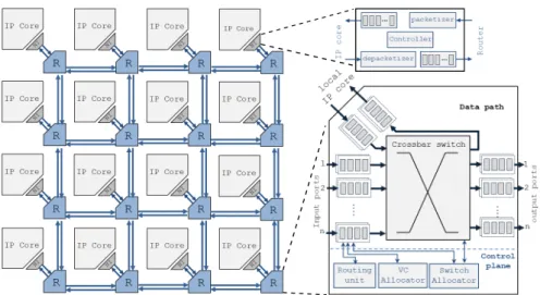
Figure2.1 Examples of on-chip communication network
topologies. . . 12 Figure2.2 main components of network-on-chip (NoC) such
as router(R) and network interface (NI) common micro-architecture. . . 14 Figure2.3 Example scenario of a deadlock resulting from
cyclic channel dependency. . . 15 Figure2.4 illustration of segmentation and the
encapsula-tion process of message into packets, flits, and phits depending on theNoCresources and the flow control techniques. . . 16 Figure2.5 Example scenario showing the benefit of using
virtual channels (VCs) on mitigating blocking channels issues, even though the buffer size re-main the same. . . 18 Figure2.6 illustration of the allowed (solid arrows) and
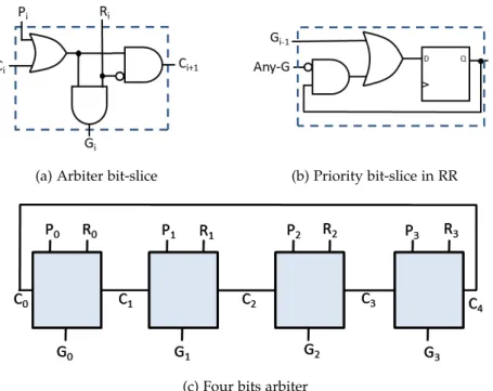
prohibited (dashed arrows) turns in different turn-model routing algorithms in two-dimensional (2D) mesh networks-on-chip (NoCs) . . . 21 Figure2.7 Examples of basic arbiters, where R is request,
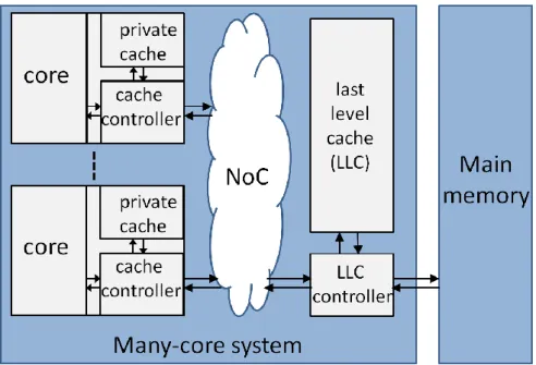
P is priority, C is a carry, G is grant, and Any-G=|(G0...Gn−1). . . 22 Figure2.8 Structure of distributed cache for many
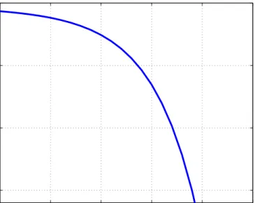
multi/many-core processors. . . 24 Figure2.9 Projected delay issues of global regular wire
com-pared to gate delay with technology scaling [7]. . . 27 Figure2.10 Structure of the main three types of the
trans-missions lines: (a) microstrip line (MSL), (b) dif-ferential line or coplanar strips (CPS), and (c) coplanar waveguide (CPW). . . 33
Figure2.11 Zenneck surface wave propagation decay which is significantly better than free space propaga-tion [105]. . . 34 Figure2.12 The corrugated surface. . . 35 Figure2.13 Flat surface wave signal power loss proportional
to frequency in the case of a dielectric mate-rial with relatively high loss tangent (Tan-Loss). These results obtained in collaboration with K.Tong in University Collage of London . . . 36 Figure2.14 Comparison of forward transmission gain (S21)
be-tween Wireless [22] and SW interconnects [105]. . . 37 Figure3.1 Integrated transceiver and integrated transducer
(in-verted quarter-wavelength monopole) stacked over the designed surface. . . 47 Figure3.2 Surface wave interconnect communication
chan-nel with multi sub-chanchan-nels where the master node transmit through the shared surface to slave node(s). . . 48
Figure3.3 Experiment results showing power decay with
distance for a range of frequencies [35]. . . 51 Figure3.4 Measurement versus calculated voltage gain
com-parison for different frequencies. . . 51 Figure3.5 Bit-Error-Rate vs. SNR for16-QAM modulation
sub-channel (SC). . . 52 Figure3.6 The surface-wave experiment set-up. . . 53
Figure3.7 The surface-wave experiment equipment
align-ment and set-up. . . 54 Figure3.8 S21measurements results for the corrugated
sur-face, flat sursur-face, free-space, and the case where transducers connected face-to-face for wide range of frequencies. . . 55 Figure3.9 S21 measurements results for the flat surface
shows signal attenuation with distances for wide range of frequencies. . . 55 Figure4.1 Example showing that inserting two SWI channels
in the proposed hybrid wire-SWI multilayer-network increases the overall NoC bisection bandwidth: (a) conventional on-chip network layer with 4-ary 2
-mesh topology; (b) connections of both layers, metal wire and SWI. . . 60
Figure4.2 Closing the gap towards small world
phenom-ena in a10×10NoCas the number of nodes with transmission capability via Zenneck surface-wave interconnect (SWI) (Nm) increased. . . 61
Figure4.3 Example of 4 master placement in a 6×4 NoC based on simple simulated- annealing optimiza-tion algorithm with target to minimize the average-hop-count from all slaves to the nearest master. 62 Figure4.4 An illustration example showing the master node
routing decision, which is either forwarding the traffic via SWI or continue via regular Mesh. . 64 Figure4.5 Energy dissipation per bit according to on-chip
communication distance for buffered wire [22] and SWI. . . 65
Figure4.6 DWA implementation, where CSR provide the
round robin functionality and store the weight code. . . 66 Figure4.7 The conducted system-level evaluation flowchart
shows the methodology and tools used to obtain the results. . . 67 Figure4.8 6×4Network average delay verses PIR for
W-SWI and baseline architecture. . . 68 Figure4.9 6×4Network throughput verses PIR for W-SWI
and baseline architecture. . . 69
Figure4.10 Comparison between W-SWI with DWA
algo-rithm and with basic Round-robin (RR) Com-munication power saving ratio to the Mesh for different network size and traffic scenarios. . . . 71 Figure5.1 (a) The non-trivial1-to-M traffic percentage
ac-cording to the simulation of a range of chip-multiprocessor (CMP) benchmark applications
(from PARSEC and SPLASH2) with modified,
exclusive, shared and invalid (MESI) cache coher-ence protocol; (b) our6×6 regular mesh NoC simulations with random traffic plus random traffic with a small percentage of multicast or broadcast (5%). The introduction of multicast or broadcast leads to severe deterioration in perfor-mance in terms of latency and saturation packet injection rate (PIR). . . 76 Figure5.2 Demonstration of different1-to-M routing schemes:
(a) path-based delivers packets sequentially in a worm-like route5.2a, (b) Tree-based delivers the packets in
a tree-like route [16,15]. . . 78
Figure5.3 Illustration example of multicast dependency
that causes deadlock in tree-based multicast rout-ing [156]. . . 78 Figure5.4 Optical-based interconnect architecture examples that
Figure5.5 Examples of multicast clustering in WiNoC-based
interconnects architectures. . . 80 Figure5.6 Examples of some RF-I multicast architectures [18,
19]. . . 82 Figure5.7 W-SWI improved tree-based with low latency packet
delivery where branching possible only at the SWI master nodes . . . 84 Figure5.8 Demonstration of the deadlock problem created by
the multicast dependency. . . 85
Figure5.9 The proposed MAB-check unit to mask the
re-quests unless all the requested multicast group are free. . . 86 Figure5.10 Design of the proposed global multi-resource arbiter
(GMA) for SWI channels: stage (1) request masking;
stages (2-4) achieve legal match with lonely output
allocator [51]; stage (5) generates the grant signals
for a fixed period. The figure also shows an example of GMA stages1-4with four masters and two VCs.
Master (M4) related logic is not drawn, for
simplic-ity, but it is currently allocating some of the slaves requested byM2. . . 89 Figure5.11 Demonstration control signals of SWI communication
protocol exchanged between master, slaves and the GMA. . . 91 Figure5.12 Average delay results of6×4NoC with the
follow-ing: (a) comparison of Mesh and W-SWI-C under random traffic with 10% broadcast; (b) W-SWI-C with different allocation techniques; (c) W-SWI-C with different SWI master number. Note that W-SWI:Nm:VCNv:ArbPrefers to W-SWI withNm
num-ber of masters,Nvnumber of VC andPnumber of
grant cycles. Hold is where GMA grants a master until all its current data flow is transmitted.. . . 93 Figure5.13 Communication power saving ratio of the W-SWI
over the Mesh for different network sizes, types of synthetic traffic and broadcast/multicast ratios. . . 95 Figure5.14 Packet delay distribution comparison of W-SWI and
Mesh with software multicasting for a 6×4 NoC with5% broadcast. . . 96 Figure5.15 Average delay comparison of NoC (6×4) between
W-SWI and VCT and Mesh under SNN benchmarks for different NoC size. . . 98
Hold allocation mechanism (b) W-SWI-C architecture with fixed period (one cycle) alternation and two VSWI, and (c) W-SWI-D architecture (decentralized arbitration and stretched multicast), whereMis a master,Sis a slave andT is a time slot. . . 103 Figure6.2 Illustration of router micro-architecture with ID-Tagging
based flow control andVCflow control. . . 105 Figure6.3 Simulation flow to obtain the results. . . 109 Figure6.4 Comparison between the average delay of W-SWI-C
and W-SWI-D under uniform synthetic traffic with
10% multicast ratio for different VC number and NoC
size. . . 111 Figure6.5 Comparison between the average delay of W-SWI-C
and W-SWI-D under uniform synthetic traffic with
5% and10% broadcast ratios. . . 112 Figure6.6 Comparison between the average delay and energy
improvements of W-SWI-C and W-SWI-D over Mesh under real applications benchmarks from PARSEC [150] and SPLASH2[151] for10×8NoC. . . 115 Figure A.1 (a)Demonstration of router ports with threeVCs;
(b) The added control signals between tiles to simulate threeVCsin this example. . . 123
L I S T O F TA B L E S
Table2.1 Summary of reported key features for
imple-mentation of integrated optical interconnects. . 28
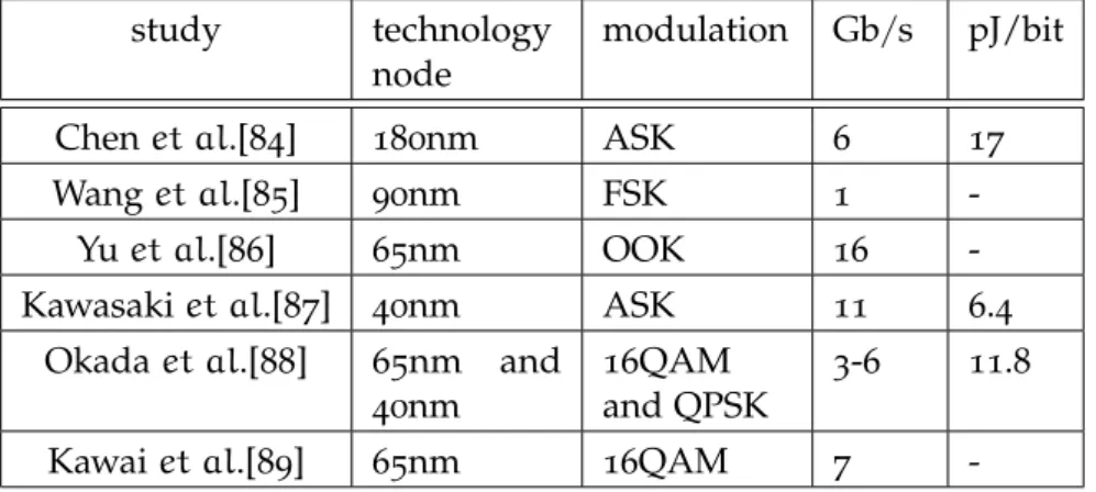
Table2.2 Examples of demonstrated integrated wireless
communication systems along with their key features for a single link. . . 30
Table2.3 Examples of reported implementations of
inte-grated transmission lines along with their key features for a single link. . . 32
Table2.4 Summary comparison of key features in current
and emerging on-chip interconnects. . . 38 Table2.5 Comparison of variousNoCmodels and simulators. 43 Table4.1 The adopted parameters of the NoC based
multi-processor chip ( consists of6×4tiles). . . 63
plementary metal-oxide-semiconductor (CMOS) technology has scaled. . . 67
Table4.3 W-SWI PIR and throughput improvement over
Mesh at the edge of network saturation where latency reach double the zero-load-latency (ZLL). 70
Table4.4 W-SWI average delay and throughput
improve-ment over Mesh for a range of applications . . . 70
Table4.5 Area overhead consideration for the proposed
Architecture comparing to related Architectures. Noticed that some component are needed only in the Master nodes . . . 72 Table5.1 Average delay and PIR at the edge of NoC saturation
comparison of the W-SWI and VCT. . . 97
Table5.2 Area overhead evaluation for W-SWI-C,
pro-posed W-SWI-D and VCT-512[15] over baseline architecture (Mesh). . . 99 Table6.1 Notations used in this chapter. . . . 102 Table6.2 Comparison of highlighted features of the
central-ized and decentralcentral-ized approaches for the proposed architecture. . . 106 Table6.3 Results improvements over Baseline architecture
(Mesh) comparison between W-SWI-C and the proposed W-SWI-D with10% multicast ratio. . 114
Table6.4 Area overhead evaluation for W-SWI-C,
pro-posed W-SWI-D and VCT-512[15] over baseline architecture (Mesh). . . 116
L I S T O F A L G O R I T H M S
4.1 Distance based weighted random arbitration algorithm(DWA). 65
5.1 procedure of centralized arbitration and allocation using
global-multiresources-arbiter (GMA). . . 87 6.1 Master interfaces procedure to communicate via SWI. . . . 107 6.2 slave interfaces procedure to communicate via SWI. . . . . 108
A.1 Algorithm of the generation of one-to-many (1-to-M) or
one-to-all (1-to-all) traffics and the way of injected them
based on the architecture that handel the multicast-traffic; Where N is the number of nodes and Flit.M is the multicast flag bit. . . 124
A C R O N Y M S 1-to-M one-to-many 1-to-all one-to-all 1-to-1 one-to-one 2D two-dimensional 3D three-dimensional
3D-ICs Three-dimensional integrated circuits
BER bit error rate
CDMA code-division-multipliable-access
CMP chip-multiprocessor
CMPs chip-multiprocessors
CMOS complementary metal-oxide-semiconductor
CPS coplanar strip
CPW coplanar waveguide
CSR circular-shift-register
DOR dimension-ordered routing
DVFS dynamic voltage and frequency scaling
DWA Distance-based weighted-round-robin arbitration
EM electromagnetic
FIFO First-In-First-Out
FDMA frequency-division-multipliable-access GPU graphics processing unit
ID identity
IC Integrated circuit
IP intellectual property
IPs intellectual properties LLC last-level-cache LSB least significant bit LOA lonely output allocator MAB multicast-address-bits
MESI modified, exclusive, shared and invalid MPSoCs multiprocessor systems-on-chip MSL microstrip line
NI network interface
NIs network interfaces
NoC network-on-chip
NoCs networks-on-chip
OOK On-off keying
ONoC optical network-on-chip ONoCs optical networks-on-chip
PE processing element
PEs processing elements
PIR packet injection rate
QAM quadrature-amplitude-modulation
QoS quality of service
RF radio frequency
RF-I RF-interconnect with transmission-line RF-Is RF-interconnects with transmission-lines
RR round robin
Rx receiver
SC sub-channel SCs sub-channels SoC system-on-chip SoCs systems-on-chip SNR signal-to-noise-ratio SNN spiking-neural-network SNNs spiking-neural-networks
SCC single-chip cloud computing
SWI Zenneck surface-wave interconnect
SW Zenneck surface-wave TSVs through-silicon-vias TSV through-silicon-via TL transmission-line TLs transmission-lines Tx/Rx transceiver VCs virtual channels VC virtual channel
VLSI very large scale integration VCT virtual-circuit-tree
VSWI virtual-channel for surface-wave-interconnect VSWIs virtual-channels for surface-wave-interconnect WDM wavelength-division-multiplexing
W-SWI wire and surface-wave interconnects W-SWI-C W-SWI centralized
W-SWI-D W-SWI decentralized WiNoC wireless network-on-chip WiNoCs wireless NoCs
Thesis Chapters
1
I N T R O D U C T I O N
1.1 m o t i vat i o n
Market demand for ever more complex and sophisticated digital elec-tronic systems has led to the exponential scaling of integrated circuit technology processes, as predicted by Moore’s law. In addition, the scaling cost and limited bandwidth of off-chip communication have motivated the design option of integrating more on-chip system com-ponents to keep most communication on-chip [1]. This causes an intensification of current and future system-on-chip (SoC) in terms of the number of integrated intellectual property (IP), which includes processing elements, memories and application-specific intellectual properties (IPs). Consequently, the volumes and numbers of commu-nications have also increased dramatically. As a result, a bus-based interconnect architectures, which have been managing the on-chip communication since the introduction ofSoC, could no longer satisfy the communication requirements.
Therefore, the research community [2,3, 4] and industrial organi-zations [5, 6] have adopted the network-on-chip (NoC) as a scalable underlying communication structure over the regular bus-based inter-connect architectures. Although networks-on-chip (NoCs) offer system designers scalable and adaptable on-chip communication and a plug-and-play design approach, the fundamental physical channels, where the signal is transmitted by charging and discharging the whole wire, remain the same. Therefore, as capabilities of the physical-foundation of the on-chip interconnects are stretched to their limits with each technology scaling, a growing burden is placed on the wire-based NoC.
This is due to the fact that the downscaling of the complementary metal-oxide-semiconductor (CMOS) targets gate nodes rather than wires in terms of performance and power consumption. Therefore, as we enter the sub-micron zone, on-chip communication becomes a performance bottleneck and dominates power consumption. Thus, regular metal-based NoCs struggle to match this scalability, especially for global communication, in terms of latency and energy (J/bit) [7,8]. Moreover, the cross-section of the wires is decreasing [7] and thus its resistivity is increasing, which causes higher power dissipation. Therefore, the issue is not only that metal wire does not scale enough to match future interconnect requirements, but also that its performance is projected to get worse in terms of power and latency.
Moreover, in addition to these wire issues, given the nature of multi-hop NoC communication, providing efficient across-the-chip communication is also becoming a serious challenge. Some studies have proposed3D-integration to ease global communication issues by reducing the averageNoChop-count. However, although promising, this technology faces various technical challenges such as process control requirements, wafer thinning, low through-silicon-via (TSV) capacitance and design challenges [9,7,10].
These intra-chip communication challenges are especially pertinent for chip-multiprocessors (CMPs), which were introduced to provide near-linear performance improvements when complexity increases while maintaining lower power and frequency budgets [11]. Therefore, the International technology roadmap for semiconductors (ITRS) pre-dicts that we will reach the many-core era in only few years where hundreds of cores are integrated, as shown in Fig.1.1. This will be real-ized in the very near future since some graphics processing unit (GPU) chips has been already fabricated with thousand cores [12]. The in-crease in numbers of cores, but not their complexity, along with the projected wire issues, will increase the proportion of power budget accounted for communication rather than computation. Also, these factors will make performance increasingly determined by inter-core communication rather than core-complexity. For instance, the NoC power budget for8×10 CMP TeraFLOPS, is reported to be around 35% [6]. Consequently, many-core systems design has shifted from computational-centric to communication-centric [13].
Figure1.1: Processing element number is projected to scale exponentially
according to ITRSSoC[14].
On the other hand, multi/many-core performance and power con-sumption depends not only on theNoC, but also on cache coherence protocols. Cache coherence protocols generate a range of multicast ( one-to-many (1-to-M)) or broadcast (one-to-all (1-to-all)) communication
of number of destinations, burstiness, and spatial distribution as the number of cores scale up [17]. For instance, broadcast-based cache coherence protocols produce a relatively high broadcast ratio over total packet injection rate (PIR) of up to52.4% [16, 15], as shown in Fig 1.2a. This could be catastrophic for global coherence and NoC performance unless the on-chip interconnect fabric supports 1-to-M
communication. Fig.1.2b shows the severe effect of broadcast traffic scaling on theNoCperformance. Therefore, there is a need to overcome these constraints and improve performance by using new interconnect architectures that support multicast. Relevant NoC studies, at most, aim to achieve1-to-Mlatency and energy levels close to wire-latency
and wire-energy [16,15]. Again, this will not be sufficient in the near future given the projected issues with regular metal-based NoCs, since these interconnect fabrics struggle to match the required scalability in terms of latency and energy (J/bit) [7,10].
0% 10% 20% 30% 40% 50% 60% 70% 80% 90% 100% x 2 6 4 b a rn e s fft fm m lu n lu ra d ix w a te r-n s q w a te r-s p a ti a l b la c k s c h o le s c a n n e a l fl u id a n im a te s w a p ti o n s x 2 6 4 SPLASH-2 PARSEC M-to-1 1-to-M 1-to-1
(a) 5 10 15 x 10−3 0 100 200 300 400 500 PIR (Packet/Cycle/Tile)
Average delay (Cycle)
0% Broadcast 1% Broadcast 5% Broadcast 10% Broadcast
(b)
Figure1.2: (a)1-to-M, M-to-1and1-to-1traffic percentage in different CMP
real benchmark when a broadcast-based cache coherence pro-tocol (token coherence) is used [16], (b) NoC simulation shows
an increase in average delay and fast network saturation when broadcast treated as unicast in a6×4NoC.
Thus, the challenges facing global and multicast communication have inspired many researchers to look for alternative or supplemen-tary types of interconnect. Such emerging cutting-edge interconnects include the RF-interconnect with transmission-line (RF-I) [18,19,20,21], wireless network-on-chip (WiNoC) [22, 23, 9, 24, 25, 26] and optical network-on-chip (ONoC) [27,28,29,30]. However, these types of inter-connect themselves face various challenges, such as their complexity, power consumption and/or area overheads.
This thesis opens a new research directions in the development of new and promising on-chip communication technologies. This
study by proposing the Zenneck surface-wave interconnect (SWI) for intra-chip interconnects has already inspired several research teams to further investigate this promising technology [31, 32, 33]. This technology involves an electromagnetic wave that propagates, and is guided, through an interface between the surfaces of different me-dia. It has many remarkable features compared to state-of-the-art emerging interconnects in terms of low-power dissipation, high signal fan-out and close to the speed of light cross-the-chip propagation [34,35,36,37,38]. In addition, this thesis proposes innovative archi-tectures and technologies that maximize the utilization of theSWIand resolve their system-level challenges. As a result, the original proposed architecture demonstrates a promising and radical solution to meet future NoC-based multi/many-core processors necessities such as those concerning global and multicast communication.
1.2 s tat e m e n t o f o r i g i na l i t y
The major contributions of this thesis can be summarized as follows: • A comprehensive view is presented of current knowledge of the merits and drawbacks of emerging interconnects such as WiNoC,RF-I,ONoC, and SWI. Subsequently, this survey could be a ground for any study inspired to utilize these emerging inter-connects advantages and address their challenges. In addition, a system-level comparison of these promising types of inter-connects is provided. This comparison especially highlights the future communication functionality requirements to the under-layer physical and technologal capabilities of these fabrics [38]. • The challenges, performance, reliability, implementation, and design considerations for theSWIare studied. This has led to a quantification of the effectiveness of this promising interconnect. Moreover, an analytical model for SWI links power dissipa-tion is developed based on previous experimental results. The calculated metrics are then used for subsequent system-level evaluations [35,34].
• Experiments on different types of designed waveguide surface have been conducted to build the ground for understanding of SWIfeatures [39].
• A wire and surface-wave interconnects (W-SWI) interconnect ar-chitecture is proposed. This NoC arar-chitecture aims to utilize the SW features to allow future on-chip communication scalability. In addition, these efficient short-cut links are placed so that the resulting network topology reduces the intra-core average hop count. This two-layer NoC architecture has considerable
advan-tages in terms of connectivity, since it employs the merits of both mesh and configurable bus topologies [35,34].
• The hybrid W-SWI architecture is improved to mitigate global communication issues. This is achieved by developing a Distance-based weighted-round-robin arbitration (DWA) arbitration tech-nique. This simple and efficient technique intelligently prioritizes surface-wave channels over metal wires, without saturating these channels, in the case of global communication. The proposed DWAis synthesised and tested so that measurements can be used in a system-level simulator. Evaluations are conducted using this cycle-accurate simulator, which show improvements in av-erage delay (34%), throughput (35%), and power consumption (12to23%). In addition, these improvements are achieved with negligible cost [35].
• A tree-based multicast routing scheme is developed that exploits the W-SWI architecture for1-to-M traffic handling. This routing
scheme enabled bySWIis superior to other state-of-the-art multi-cast/broadcast routing schemes in terms of latency and power consumption, since it forks the packet only at the destination routers. In addition, it requires only relatively minor alteration to the baseline router micro-architecture [36,40]
• A W-SWI centralized (W-SWI-C) is proposed for1-to-Mtraffic that
efficiently addresses multicast traffic contention issues and maxi-mizes SWI utilization. In particular, a novel global-multiresources-arbiter (GMA) is designed and a detailed design rationale, hard-ware realization and schematic are presented. This centralized arbitration and allocation unit has the ability to allow the con-current utilization of many resources with relatively low circuit complexity and delay [36,40].
• TheW-SWI-Cis rigorously evaluated using a cycle-accurate simu-lator for both synthetic traffic and real application benchmarks. Moreover, the proposed GMA is synthesised and tested. This proposed architecture is found to surpass previous related work by achieving improvements in average delay (∼22x), power con-sumption (∼2−10x), and attaining a reliable quality of service. Moreover, the additional hardware cost of the W-SWI is found to be relatively insignificant [36,40].
• A W-SWI decentralized (W-SWI-D) architecture is introduced which deploys novel techniques such as stretch-multicast and ID-tagging flow control. These efficient and flexible decentralized arbitration schemes maximize the hybrid architecture’s utiliza-tion and contenutiliza-tion handling for1-to-Mtraffic. These techniques
• The proposed W-SWI-Cis compared and evaluated thoroughly against W-SWI-D in terms of latency, power consumption and area overheads. TheW-SWI-Dhas been found to perform better when traffic levels are relatively low, but worse when the load reaches the NoC saturation points and case of broadcast. The evaluation also demonstrates that W-SWI-C has less area over-head compared toW-SWI-D, but both have relatively negligible area overheads compared to state-of-the-art on-chip multicast interconnect architectures [37,40]
1.3 t h e s i s o r g a n i z at i o n
This thesis is organized into seven chapters, as shown in Fig.1.3. Two main requirements of future many-cores are tackled, which are global and multicast communication, using the proposed hybrid wire-SWI architecture. The Surface-wave interconnects is covered in Chapter3, while Chapter4introduces the proposed hybrid architecture and ad-dresses the on-chip global communication requirements. On the other hand, Chapters5-6cover original techniques based on the proposed architecture to handle multicast communication challenges.
Chapter 1 "Introduction": introduces the motivations, objectives, contributions and structure of this thesis.
Chapter 2 "Background and Literature Review": provides back-ground information and summarizes the literature on topics relevant to this thesis. In addition, the emerging on-chip interconnects included in recent literature are reviewed and discussed in detail.
Chapter3"Surface-wave On-chip Interconnects": proposes the novel SWI, discusses its merits and challenges, and develops an analytical model of power consumption and performance for theSWI.
Chapter4"Hybrid Wire and Surface-wave Architecture for On-chip Global Communications": proposes the Hybrid wire and surface-wave interconnects architecture W-SWI and discusses the utilization and efficiency of this proposed architecture for global/semi-global on-chip communication.
Chapter 5"Wire and Surface-wave Architecture with Centralized Control for Multicast" proposes an original deadlock-free centralized arbitration and allocation technique that exploits the merits of the W-SWIarchitecture for1-to-Mcommunication. Moreover, it presents a
comprehensive evaluation of the proposed architecture and techniques compared to state-of-the-art architectures running real benchmarks.
Chapter6"Wire and Surface-wave Architecture with Decentralized Control for Multicast" further explores multicast contention issues by developing new decentralized flexible schemes. A comparative evaluation of centralized decentralized approaches is also presented.
Chapter 1:
Introduction
Chapter 2:
Background and
literature review
Chapter 3:
Surface-wave
interconnect
Chapter 7:
Conclusion and future work
Chapter7"Conclusions and Future Work" summarizes the conclu-sions of the study and discusses the implications of the presented research and draws the horizon for potential future work.
2
B A C K G R O U N D A N D L I T E R AT U R E R E V I E W
2.1 i n t r o d u c t i o n
Growing demand for complex digital systems has caused a dramatic increase in the number of integrated intellectual properties (IPs) in current and future system-on-chip (SoC). For instance, in the last decade, in order to maintain balance between further performance improvements and available power and frequency budgets, the use of small many-cores is preferred over single or small numbers of complex cores [11]. As a result, the number of integratedIPs/cores inside a singleSoChas increased dramatically.
On the other hand, volumes of inter-core or IP communication are increasing significantly. In contrast, technology scaling enables the realization of complex, yet with economic implementation, of many computational or control components. Therefore, on-chip communi-cations are becoming a performance bottleneck for future systems-on-chip (SoCs), including chip-multiprocessors (CMPs), due to the growing burden caused by scalability requirements. As a result, a communication-centric design has become vital for current and future SoCs[41,13].
Consequently, the network-on-chip (NoC) has been proposed for over a decade now as a way to tackle the challenges and requirements of on-chip communication. Since then, rapid advances inNoCdesign have been achieved by the research community [2,3,4,42,43,44] and industry [5,6,45,46,47].
This chapter reviews the main concepts ofNoCincluding architec-tural components, topologies, routing, switching and flow control. Moreover, cutting-edge current and emerging types of interconnects are discussed along with recent ground-breaking advances in these fields by academic and/or industrial entities.
2.2 b a c k g r o u n d 2.2.1 Networks-on-chip
On-chip communication since the introduction of theSoC had been limited to either bus architecture, point-to-point interconnect, or a mix of both until the last decade. In the former, the bus consists of single shared wires (a physical channel) that is accessible by a set of logical components via their logical channels. Even though this architecture has relatively low area overheads and high fan-out capability, it suffers
from performance and power limitations [48]. This is still true even when the bus architecture evolved into a hierarchical bus of which segments of the bus are connected via bridges that could buffer the data, such as the AMBA [49].
The second architectural approach is the point-to-point wire inter-connects. This is the simplest type of interconnect, which consists of dedicated physical channels that link each two components in the sys-tem. However, the number of channels grow rapidly as we increase the numbers ofIPsor cores (N) that need to be connected (O(N(N−1))). In addition to the cost of many such physical channels, the routing of these wires inside the chip could become a nightmare.
The NoC has emerged as the underlying on-chip communication
structure, which offers the best cost/performance trade-off that meets scalability requirements. These networks-on-chip (NoCs) were inspired by data communication networks, and such an architecture consists of a network constructed from multiple point-to-point data channels (links) interconnected by routers. The routers are connected to a set of distributedIPs/cores and communication among these usually utilizes a packet-switching method where messages are divided into suitably-sized blocks, called packets. This section briefly introduces the main concepts of the NoC.
2.2.1.1 NoC Topology
Network topology is the arrangement or pattern in which the network nodes are connected using physical channels. For theSoC, these nodes could refer to any intellectual property (IP) component such as pro-cessing elements (PEs) and memories in the case of a direct network or routers and switches in the case of an indirect network [3]. However, since indirect networks provide more efficient connectivity with large numbers ofIPs, mostly theNoCare indirect networks and the nodes are referring to routers. The first step in designing a network is to determine its topology that should balance connectivity requirements and the resources available. In other words, the best trade-off between performance and cost should be found. The second step is to ensure that the resulting topology connects all of the nodes.
Fig.2.1 illustrates a few common on-chip network topologies. Al-though the bus shown in Fig. 2.1a was until the last decade the most common topology, scalability requirements have necessitated the search for alternatives. Fig. 2.1b presents a ring topology that, although slightly better than the bus, still suffers from fast network saturation. The butterfly topology shown in Fig.2.1c has a low network diameter and known packet delivery delay. However, it does not offer path diversity unless a further layer of routers is added and it cannot be implemented without relatively long wires. The same drawbacks exist in crossbar networks in terms of a lack of path diversity and the need for long wires, as shown in Fig.2.1d. Moreover, even though it
(a) Bus (b) Ring
(c) Butterfly (d) Crossbar
(e) Tree (f) Irregular
(g) Mesh (h) Torus
involves the attractive one-hop communication, the cost of the crossbar increases exponentially as the number of nodes are increased. The tree topology shown in Fig.2.1e has low zero-load-latency, but net-works are also saturated very quickly as the packet injection rate (PIR) increases since the root becomes a bottleneck.
The torus and mesh topologies demonstrated in Fig.2.1h and Fig. 2.1g, respectively are the most common topology for general purpose NoCs. This is due to their many desirable features such as physical arrangement suitable for chip floor planning. Moreover, the uniform physical arrangement benefits applications with high communication locality characteristic where communication with neighbours is more common than with the rest of the network. In addition, these topolo-gies have characteristics of path diversity, load balancing, and high throughput. The mesh has shorter wires than torus especially if the latter is unfolded. Moreover, although the torus has a lower average hope count, both the mesh and torus have higher average hop counts than the butterfly, crossbar and tree topologies.
On the other hand, there are some irregular application-specific network topologies where the designer tailors the network to the application’s communication requirements, as in Fig.2.1f. However, such networks have very low adaptivity to changes in the injected application load. In addition, they also have the drawback of long wires and/or non-uniform and high switches degrees. As a result, these network topologies are very limited. On the other hand, some designers have tried to combine more than one topology to utilize benefits of both topologies, but the resulted topology performance should justify the extra cost involved [50].
2.2.1.2 NoC Component
The NoC may include different devices based on architecture and design requirements. This section briefly describes the most common NoCcomponents. Fig.2.2shows a regularNoCwith mesh topology and how its components such as routers, links, and network interfaces (NIs) are connected. In addition, a block digram of the micro-architecture is given of a typical router and network interface (NI).
The router is responsible for directing the packets towards their destination. In addition, the router applies the routing algorithm and performs the flow control, as will be discussed in Sections2.2.4and 2.2.3. The router’s building blocks can be classified as either data path or control plane as shown in Fig.2.2. The data path includes all the units that store and pass packets such as input/output buffers and crossbar switches. On the other hand, control plane units manage and coordinate the movements of packets in the data path units.
Once the packet arrives at the input port, it is stored in the FIFO buffer. Then the routing information is extracted and sent to the routing unit that determines the possible output port(s). In cases
Figure2.2: main components ofNoCsuch as router(R) and network interface
(NI) common micro-architecture.
where the router design includes multiple virtual channels (VCs) per port, the virtual channel (VC) allocator and arbiter reserve the output VCfor the specific inputVC. After that the switch allocator reserves switch time slots, since it is only allowed to link at most one input port to at most one output port. As a result, the data passes to the output port buffer where it must wait until it is transmitted via the physical channel. These pipeline steps might be different and/or completed simultaneously to improve crossing latency depending on the router design. Moreover, these pipelined steps are either conducted per flit or packet. For instance, routing andVCallocation are conducted per packet only. This reduces the dynamic power and crossing latency [51]. More information about the flow control of packets and flits will be discussed in Section2.2.3.
Network interfaces are much simpler than routers. Their task is simply to link the localIPcores with the routers. This task requires the packetization and depacketization of the payload message. Also, it may include the temporary storage of the packets to and from the localIPcores.
2.2.2 Deadlock, Livelock and Starvation
A packet might not reach its destination, or may fail to progress even though there is no failure in the network. This is due to problems such as deadlock, livelock and starvation. Generally, these problems are caused because of finite network resources. Therefore, careful consideration is required when designing the techniques used to forward packets from thier source to destination in order to avoid or recover from these problems.
Channel starvation can result from a request for a network resources never being granted because the arbitration always or frequently grants other requests. For instance, packet starvation will exist if a packet keeps requesting a crossbar switch time slot, which is always granted to other ports. This issue can easily be handled by adopting a fair arbitration and allocation mechanism.
Figure2.3: Example scenario of a deadlock resulting from cyclic channel
dependency.
Deadlock results from the cyclic dependency of packets reserving some network resources and requesting those of each other. For ex-ample, Fig. 2.3 shows how packets A, B, C, and D are requesting channels reserved by B, C, D, and A, respectively, which creates a cycle of dependency. This situation will prevent any of these packets from progressing unless one or more of them releases the channels it has already reserved. This is a very serious problem that might paralyse the whole network since it increases the number of blocked packets even if they are not part of the deadlock scenario [52]. This problem is usually solved either by deadlock avoidance or deadlock recovery. The former tries to remove the conditions that lead to the deadlock scenario, such as restricting some routing turns or removes packet dependency by implementing virtual channels, see sections 2.2.3.5and2.2.4.1. On the other hand, deadlock recovery tries to detect a deadlock occurrence and then recover from it.
The third problem, which is livelock, is usually associated with nonminimal adaptive routing, which discussed in Section2.2.4. In this case, the packets are not stopped from progressing, yet they also do not reach their destinations. This is due to the packet continuously being misrouted in a cyclic manner due to the blocking or congestion of channels in the path toward the destination. The solution to such a problem includes restricting some paths, adopting minimal path rout-ing, limiting the number of misroute, or using probabilistic avoidance [3,51].
2.2.3 Flow Control
Flow control is the techniques to efficiently balance network resources such as buffers and physical channels among travelling messages. An effective flow control utilizes these resources and achieves higher band-width and lower latency. This can be viewed as resources allocation problem, so that these resources should be allocated more efficiently. Also, it can be considered as contention handling when two messages requesting the same resources [51].
Figure2.4: illustration of segmentation and the encapsulation process of
mes-sage into packets, flits, and phits depending on theNoCresources and the flow control techniques.
Based on the resources available and the flow control techniques used, the data messages might need to be segmented into packets. This segmentation process is called packetization, which is achieved by the NIs. The data segment or payload is encapsulated by the packet header and tail that include information such as the destination, packet ID number, time stamp, and various status flags. For the same reason, the packet might also be divided into smaller units called flits. These are either header, tail, or payload flits and each also has its own header. A flit might also be divided into even smaller segments called phits. Fig. 2.4shows the segmentation and structure of packets, flits and phits.
The following sections describe the main flow control techniques along with their advantages and disadvantages.
2.2.3.1 Circuit Switching
Also known as bufferless flow control, this basically sets up the physi-cal channel from the source to the destination using a routing header or probe that is transmitted before the data. After receiving an acknowl-edgement that a physical channel is reserved, the data is transmitted. This type of techniques is suitable for infrequent and long messages and where buffer avoidance is one of the design requirements.
2.2.3.2 Store and Forward
Also known as packet switching, this can buffer the whole packet in intermediate routers. In this way, there is no need to wait until all phys-ical channels are free. Moreover, This also will improve physphys-ical links utilization by avoiding keeping segments of physical links ideal and no longer needed until the packet reaches its destination. As a result, network efficiency in terms of latency and throughput is increased due to the network’s ability to handle more packets simultaneously. 2.2.3.3 Virtual Cut-Through
In this technique, the router does not need to wait until the whole packet arrives. Instead, once the packet header that contains all the routing information has arrived, it starts to forward the packet. These pipelined packets improve further the effectiveness of the network. However, in highly congested networks the packets will be delayed for longer in each node, and thus the network will behave like a store-and-forward flow control.
2.2.3.4 Wormhole
Due to increased message size, the buffer size might be too small to hold the whole packet. Therefore, allocation can be accomplished on a flit basis and the packet might be extended over a few routers. The benefits of this technique are the low hardware resources needed, such as buffer size and physical channels, as well as its efficiency. Rout-ing and port allocation are required only for the header flit, which is routed ahead of the rest of the packet. Then the other flits follow the same path as the header flit where they only need to reserve the switch time slot, as shown in Section2.2.4. When all flits have been forwarded, the tail flit will release the reserved channels. Even though the wormhole is considered a very cost-effective technique, it makes the network more vulnerable to deadlock and contention issues since each packet might reserve several channels simultaneously. There-fore, careful consideration should be given to routing and contention handling techniques.
2.2.3.5 Virtual Channels (VCs)
Router buffers usually operate as FIFO queues. Therefore, if the packet is blocked because of congestion, for example, all the packets behind it will be blocked as well. Alternatively, the input and output buffers can be divided into separate FIFO queues that can be allocated separately. These are widely known asVCs, which were first proposed to avoid deadlock in wormhole flow control [51,3]. This flow control technique allows the decoupling of physical channels and buffer allocation, which increases the flexibility of sharing network resources. However,
the flits in eachVClane have to compete for physical channels. This requires the addition of aVCallocation unit, as discussed in Section. 2.2.1.2. This unit might add an extra pipeline stage for the router crossing.
Figure2.5: Example scenario showing the benefit of usingVCson mitigating
blocking channels issues, even though the buffer size remain the same.
EachVCbuffer either can have a static size or dynamically allocated size from a main buffer. Moreover, buffer size does not need to be increased when it is replaced by several queues. According to Dally [53], network will achieve high throughput and latency improvements by increasing the number ofVCs even when the buffer size is kept constant. However, there is a limitation to the increase in the number ofVCswhere network performance starts to decay due to the latency in allocation and arbitration processes for high numbers ofVClanes. On the other hand, theVCcan be used for other purposes, such as quality of service (QoS) and deadlock avoidance, by restricting their allocation.
Fig.2.5demonstrates the benefits of usingVCswhile keeping buffer size constant. In this example, the router input and output buffers have the size of four and two flits, respectively. The first scenario shows wormhole flow control where packet A is currently blocked, keeping the physical link between the two routers ideal and blocking packet B.
In the second scenario, both input and output buffers are divided into twoVCs. Consequently, packet B can bypass packet A similar to when a car bypasses another slow car using another street lane. As a result, many router micro-architectures adopt this technique for flow control. 2.2.4 Routing Algorithms
The routing algorithms represent the process of calculating and de-termining the packets path from their sources to their destinations. In router design, the routing unit consists of two functions: routing and selection. The routing function calculates the possible output ports based on packet routing informations such as the destination address and the input port. These options then enter the selection func-tion, which selects one of them either randomly or based on routing information and/or network status.
Routing algorithms can be classified based on several criteria. In this thesis, the most common criteria are briefly listed below along with their pros and cons:
• Based on the number of destinations: routing algorithms could be for unicast (one-to-one (1-to-1)), multicast (one-to-many (1-to-M))
or broadcast (one-to-all (1-to-all)). These different types of traffic
exist in networks in different proportions depending on the run-ning application and used protocols. Unicast routing algorithms can be used for all other types if the message is to be duplicated to all destinations. This is known as software multicast, which significantly overloads the network even with small multicast PIR.
• Based on adaptivity: the routing algorithm could be determinis-tic, partially adaptive or fully adaptive. The first type is when the route from each source to every destination is already deter-mined regardless of network status. As a result, router complex-ity will be reduced. In contrast, fully adaptive routing algorithms allow the option of path diversity based on network status such as the existence of congestion and faulty links. Although this makes the network more efficient in cases of non-uniform or bursty traffic, this might require very complex router design. On the other hand, partially adaptive routing algorithms try to achieve a compromise between the merits of path flexibility and router complexity by allowing only subset of routes to be selected.
• Based on routing decision maker: this criterion is used to classify the routing algorithms mainly as source routing, centralized routing, and distributed routing. In source routing, the packet path is determined from its source, which makes it mostly de-terministic routing. Therefore, routing complexity is reduced
but the packet overhead is not scalable. Centralized routing is very rare due to its lack of efficiency. This is due to the necessity for the centralized unit to distribute routing decisions to all net-work nodes. In contrast, distributed routing is considered the most favoured type of routing algorithms, where slightly more complex routers collectively determine the packet’s path to its destination.
• Based on minimality: some adaptive routing algorithms can be either restricted to minimal paths, called minimal routing algo-rithms, or are fully free to chose any path, called non-minimal routing algorithm. The former type has lower path diversity and less freedom to adopt to network changing status such as faulty link. However, minimal routing tries to use the least possible network resources and avoids further complexity in the design to avoid livelock and deadlock.
There are other criteria that can be used to categorize routing al-gorithms, such as whether or not they are oblivious and based on the implementation techniques used [3,51]. In the next section, turn model techniques are discussed as an example of popular simple routing algorithms.
2.2.4.1 Turn Model
The turn model was firstly proposed by Glasset al. [54] and these techniques are among the most commonNoCrouting algorithms. This is due to the fact that they are simple, unicast, distributed, minimal, and deadlock-free routing algorithm for two-dimensional (2D) mesh
network. Basically, turn-model techniques avoid deadlock by prohibit-ing some turns of the total possible turns, which are eight. Fig.2.6 shows a range of turn-model routing algorithms.
The XY turn mode, or dimension-ordered routing (DOR), prohibits four turns as shown in Fig. 2.6a and is therefore considered a de-terministic routing. On the other hand, negative-first, west-first, and north-last allow six turns while still offering deadlock-free routing, as shown in Fig. 2.6b, Fig.2.6c , and Fig.2.6d, respectively. Therefore, they show more adaptivity than the XY turn model.
Furthermore, Chiu has proposed another turn model that offers higher path diversity, which is odd-even [55]. This routing algorithm has two sets of rules for prohibited and allowed turns, one for odd columns and another for even columns, as seen in Fig.2.6e and Fig. 2.6f. In addition, inspired by the odd-even model, Dahiret al. have proposed a three-dimensional (3D) odd-even routing that balances the
(a) XY routing (b) Negative-First
(c) West-first (d) North-Last
(e) Odd-even: odd column (f) Odd-even: even column
Figure2.6: illustration of the allowed (solid arrows) and prohibited (dashed
arrows) turns in different turn-model routing algorithms in2D
meshNoCs
2.2.5 Arbitration and Allocation
Arbiters and allocators are the building blocks of the control plane in the routers. Arbiters are control units that resolve conflicts over shared resources such as buffers and channels. An arbitration process might be required every cycle, over fixed period of time, or until the requested agent releases the resources. On the other hand, allocators are required to match a set of request agents with a set of resources. There are two main properties of arbiters and allocators that define their effectiveness:
• Fairness: this is a property of arbiters, which means that the aver-age number of requests granted over the number of arbitrations for every request agent is the same. Otherwise, a starvation issue might rise. Although this property is preferable, different appli-cations might require different levels of fairness. For instance, some applications require fixed priority or weighted fairness in order to grants some requests more than others.
• Legal matching: this is a property of allocators. It means there is no output resource has been granted for more than one input request and there is no input request has been granted more than one resources simultaneously. A maximal match is a favourable feature since it implies maximizing utilization by assigning the
maximum number of legal matches between resources and re-quest agents.
(a) Arbiter bit-slice (b) Priority bit-slice in RR
(c) Four bits arbiter
Figure2.7: Examples of basic arbiters, where R is request, P is priority, C is a
carry, G is grant, and Any-G=|(G0...Gn−1).
Since arbiters are considered the most important components of allocators, this section discuses a few basic examples of arbiters. Fig. 2.7c shows a typical arbiter for four requests, in other words a four-bit request vector. The arbiter bit-slice is presented in Fig.2.7a. This arbiter has priority and request inputs that determine the output grant signal. The arbiter type also depends on the priority feed, which should set only one of the priority vectors at any time. For instance, if the priority is statically set for one of the requests, this is called a fixed priority arbiter, which has no fairness. However, if the arbiter is connected to 4-bit shift register with only one bit set, then it is called a circular or oblivious arbiter. This type of arbiters have weak fairness, since they are unaware of the last request that wins the arbitration. On the other hand, the round robin (RR) type has strong fairness since it enforces the rule, which states that the last winner’s request has the lower priority. Fig.2.7b shows a bit-slice of the priority control circuit ofRR. The signal Any-G=|(G0...Gn−1)allows priority values to be changed only when a grant signal is set. Moreover, other types of arbiters have been presented in the literature to deal with different arbitration and allocation challenges inNoCs[3,51,57].
2.2.6 Multi/Many-Core Processors
Since1971, when microprocessors were invented [58], performance improvements from one generation of processors to the next have been governed by Pollack’s law [11]. This states that a performance improvement is equal to the square root of complexity (or area, as-suming that the implementation uses the same CMOS technology). In other words, if we double the number of transistors, the resulting processor would have a performance improvements of40%.
Nonetheless, due to the technology scaling driven by Moore’s law, a multi-processor design possibility has emerged which overcomes Pollack’s law. This is due to the fact that using multiple processors can offer near-linear performance improvements. For instance, if the number of transistors is kept constant, a double-core processor can offer performance improvements of 70-80% compared to just 40% offered by the double-complexity single large processor [11,58]. As a result, in the last15years, the design of processors has shifted to multi-core designs. Consequently,CMPsand multiprocessor systems-on-chip (MPSoCs) have been developed and adopted by industry [59,60,6,6]. Moreover, due to projected high sub-threshold leakage and the low scaling of supply voltage, the power consumption of the die is becoming impractical [61]. As a result, the clocking frequency, which is the key element of performance speed-up for a single processor, will scale relatively slower than it used to be. The use of smaller cores with low or moderate frequency also solves this problem since the reduction of the size of the core is linearly associated with power reduction while performance is only reduced by the square root of area. Therefore, design trends have moved from multi-core (∼10’s of cores) to many-core (∼100’s of cores) since linear performance improvements can then be offered within an affordable die power budget [11].
However, Amdahl’s law states that performance improvements are limited by the serial portion of the running code [11]. Consequently, even small percentage of serial code in running application can ques-tion the effectiveness of increasing the number of cores beyond certain limit [11, 58]. This limitation is not a considerable challenge, since there are usually many applications running simultaneously with many threads. This almost ensures a good harvesting capability of the computing power of many-core processors.
In addition to the previously stated main benefits of many-core systems, they have extra design advantages such as:
• Each core can be turned on, off, or be idle, thus saving power. • Using dynamic voltage and frequency scaling (DVFS), individual
cores can be tuned to the optimum voltage and frequency, which reduces power consumption. Moreover, the use of heterogeneous many-core systems can be tailored to application requirements and power limitations.
• Many-core systems are inherently reliable since any core could replace a faulty core and/or monitor any failure. Moreover, a load balancing mechanism that distributes heat across the die can improve reliability.
• Many-core platforms speed up the time-to-market since there is no need to design a new complex core. Instead, IP/core reusabil-ity and plug-and-play design approaches are possible.
Consequently, many-cores have started to dominate the future of computing. Moreover, the intra-core communication is considered to be the backbone of such systems.
2.2.7 Cache Coherence
In all multi/many-core systems, the cores share a main memory and, in most cases, an on-chip last-level-cache (LLC) [62]. However, for each core there is usually a private cache. In this manner, the loading/s-toring of data from/in the main memory orLLCwill be significantly minimized and therefore system performance will improve [63]. In addition, such structures comply with limited power budgets yet uti-lize the ability to integrate large numbers of transistors, since memory transistors consume less power [11]. Fig.2.8presents the structure of such distributed cache systems. Other changes or improvements to this baseline architecture can be adopted, such as multi-level caches, separate cacheIPs, or a cache shared by a subgroup of cores. However, this simple tiled architecture satisfies the purpose of this section.
Figure2.8: Structure of distributed cache for many multi/many-core
![Figure 1.1: Processing element number is projected to scale exponentially according to ITRS SoC [14].](https://thumb-us.123doks.com/thumbv2/123dok_us/10223162.2926189/25.892.257.657.648.908/figure-processing-element-number-projected-scale-exponentially-according.webp)
![Figure 1.2: (a) 1-to-M, M-to-1 and 1-to-1 traffic percentage in different CMP real benchmark when a broadcast-based cache coherence pro-tocol (token coherence) is used [16], (b) NoC simulation shows an increase in average delay and fast network saturation](https://thumb-us.123doks.com/thumbv2/123dok_us/10223162.2926189/26.892.229.687.452.762/percentage-different-benchmark-broadcast-coherence-coherence-simulation-saturation.webp)
![Figure 2.9: Projected delay issues of global regular wire compared to gate delay with technology scaling [7].](https://thumb-us.123doks.com/thumbv2/123dok_us/10223162.2926189/49.892.230.686.99.389/figure-projected-issues-global-regular-compared-technology-scaling.webp)

![Figure 3.3: Experiment results showing power decay with distance for a range of frequencies [35]](https://thumb-us.123doks.com/thumbv2/123dok_us/10223162.2926189/73.892.268.683.160.447/figure-experiment-results-showing-power-decay-distance-frequencies.webp)