i
DEVELOPING AND DEPLOYING ENHANCED ALGORITHMS TO
ENABLE OPERATIONAL STABILITY CONTROL SYSTEMS WITH
EMBEDDED HIGH VOLTAGE DC LINKS
A thesis submitted for the degree of Doctor of Philosophy
by Ronak Rabbani
Supervisor: Prof Gareth Taylor
Brunel Institute of Power Systems
Department of Electronic and Computer Engineering College of Engineering, Design and Physical Sciences
Brunel University London September 2015
i
Abstract
The increasing penetration of renewable energy resources within the Great Britain (GB) transmission system has created much greater variability of power flows within the transmission network. Consequently, modern transmission networks are presented with an ever increasing range of operating conditions. As a result, decision making in the Electricity National Control Centre (ENCC) of the GB electrical power transmission system is becoming more complex and control room actions are required for reducing timescales in the future so as to enable optimum operation of the system. To maximise utilisation of the electricity transmission system there is a requirement for fast transient and dynamic stability control. In this regard, GB electrical power transmissions system reinforcement using new technology, such as High Voltage Direct Current (HVDC) links and Thyristor-Controlled Series Compensation (TCSC), is planned to come into operation. The research aim of this PhD thesis is to fully investigate the effects of HVDC lines on power system small-disturbance stability in the presence of operational uncertainties.
The main research outcome is the comprehensive probabilistic assessment of the stability improvements that can be achieved through the use of supplementary damping control when applied to HVDC systems. In this thesis, two control schemes for small-signal dynamic stability enhancement of an embedded HVDC link are proposed: Modal Linear Quadratic Gaussian (MLQG) controller and Model Predictive Controller (MPC). Following these studies, probabilistic methodologies are developed in order to test of the robustness of HVDC based damping controllers, which involves using classification techniques to identify possible mitigation options for power system operators. The Monte Carlo (MC) and Point Estimated Method (PEM) are developed in order to identify the statistical distributions of critical modes of a power system in the presence of uncertainties. In addition, eigenvalue sensitivity analysis is devised and demonstrated to ensure accurate results when the PEM is used with test systems. Finally, the concepts and techniques introduced in the thesis are combined to investigate robustness for the widely adopted MLQG controller and the recently introduced MPC, which are designed as the supplementary controls of an embedded HVDC link for damping inter-area oscillations. Power system controllers are designed using a linearised model of the system and tuned for a nominal operating point. The assumption is made that the system will be operating within an acceptable proximity range of its nominal operating condition and that the uncertainty created by changes within each operating point can possibly have an adverse effect on the controller’s performance.
Acknowledgements
Firstly I would like to express my gratitude to Prof Gareth A. Taylor for providing the opportunity to undertake this research project and for his guidance and encouragement throughout the past 4 years. I would also like to thank Dr Ahmed Zobaa for help and support. In addition I would like to express my sincerest appreciation to Dr Mohsen Mohammadi Alamuti for his valuable support and help.
And finally I would like to express my deepest gratitude to my parents, for their patience, encouragement and their support. Without their generosity, I may never have been able to survive and complete my study.
Declaration of Authorship
The work detailed in this thesis has not been previously submitted for a degree in this University or at any other and unless otherwise referenced it is the author’s own work.
i
Contents
Chapter 1
Introduction ... 1
1.1 The GB Transmission System ... 1
1.2 Power System Stability ... 4
1.2.1 Power System Oscillations ... 5
1.2.2 Wide Area Measurement Systems ... 6
1.3 Overview of HVDC Development and Technologies ... 6
1.3.1 HVDC Development ... 7
1.3.2 HVDC Technology ... 9
1.4 Research Aim and Objectives ... 11
1.5 Research Methodology... 12
1.6 Main Contributions of this Research ... 12
1.7 List of Publications ... 13
1.7.1 Journal Publications ... 13
1.7.2 Conference Publications ... 14
1.8 Thesis Overview ... 15
Chapter 2
Literature Review ... 18
2.1 Introduction ... 18
2.2 Past Research on GB Transmission System Modelling ... 19
2.3 Past Research on Damping of Power Oscillations ... 20
2.3.1 Installing New Infrastructure: ... 21
2.3.2 Installing Flexible AC Transmission System (FACTS) Controllers ... 21
2.3.3 Modifying the Control Scheme by Adopting Power System Stabilizers (PSSs) ... 26
2.3.4 Modifying the Control Scheme by Adopting HVDC Modulation and Set-point Adjustment ... 27
2.4 Past Research on Probabilistic Small-Disturbance Stability Assessment .... 36
2.5 Non-Analytical Method (Numerical Method) ... 37
2.6 Analytical Methods ... 38
2.7 Efficient Sampling Methods ... 39
2.8 Concluding Remarks ... 39
3.1 Introduction ... 40
3.2 Introduction to PSCAD/EMTDC and DIgSILENT ... 41
3.2.1 Components Modeling Comparison ... 43
3.2.2 Software Flexibility ... 48
3.2.3 Interfacing with MATLAB ... 49
3.3 Modelling of the Component ... 52
3.4 Case Study ... 55
3.4.1 Small Test System ... 55
Simulation Results ... 57
A. Steady-state Characteristic ... 57
B. Dynamic Characteristic ... 59
3.4.2 Large Test System ... 60
Synchronous Generator ... 61 Excitation ... 61 Transmission ... 62 Simulation Result ... 62 A. Steady-state Characteristic ... 62 B. Dynamic Characteristic ... 64 3.5 Concluding Remarks ... 65
Chapter 4
Probabilistic Small-Disturbance Stability
Assessment ... 66
4.1 Introduction ... 66
4.2 Power System Analysis ... 67
4.2.1 Modal Analysis ... 67 4.3 Test Networks ... 72 4.3.1 System without HVDC ... 72 4.3.2 System with HVDC ... 75 4.4 Stability Analysis ... 78 4.4.1 Uncertainty Analysis ... 78
4.4.2 Probabilistic Techniques for Small-disturbance Stability Analysis ... 79
4.4.3 The Monte Carlo Method ... 80
4.4.4 Point Estimated Method ... 82
4.4.5 Test System ... 86
4.4.6 Simulation and Results ... 88
Monte Carlo Method ... 88
Point Estimate Method ... 89
Chapter 5
Damping Controller Design ... 93
5.1 Introduction ... 93
5.2 System Linearization and the System Identification Method ... 93
5.3 Case Study ... 94
5.3.1 Signal Selection and Probing ... 95
5.3.2 Order Selection ... 97
5.3.3 Model Validation and Reduction ... 100
5.4 Damping Controller Design ... 101
5.5 Modal Linear Quadratic Gaussian (MLQG) Method ... 102
5.5.1 Application of Loop Transient Recovery (LTR)... 105
5.6 Model Predictive Control Method ... 105
5.6.1 MPC Weight Tuning ... 106
5.6.2 MPC Parameterization ... 106
5.7 Concluding Remarks ... 107
Chapter 6
Application of the Designed Controllers to a
Test System ... 109
6.1 Introduction ... 109
6.2 Test System ... 110
6.3 Power Oscillation Damping Control Design Approaches and Specification ... 111
6.3.1 SF-Based Damping Controller ... 112
6.3.2 MLQG Damping Controller ... 113
6.3.3 MPC Damping Controller ... 115
6.4 Nominal Performance of the Designed Controller ... 116
6.4.1 Small Signal Stability Performance of the Controllers ... 116
6.4.2 Transient Performance of Controllers ... 117
6.5 Assessing the Robustness of the Controllers ... 121
6.5.1 Eigenvalue Analysis... 123
6.5.2 Risk of Instability and General Comparison of the Controllers ... 123
6.6 Concluding Remarks ... 125
Chapter 7
Conclusions and Future Work ... 126
7.1 Thesis Conclusions ... 126
Appendix A
The Generator, Transformer and
Transmission Line Parameters of the
Figures
Figure 1.1 UK Energy Targets 2020 (left) and 2030 (right) ... 2
Figure 1.2 Gone Green Generation Background ... 2
Figure 1.3 New TCSC and HVDC in the GB Transmission System ... 3
Figure 1.4 Embedded HVDC Technology in an AC Grid ... 7
Figure 1.5 Meshed DC Grid ... 8
Figure 1.6 MTDC Technology ... 9
Figure 1.7 DC-Segmentation Technology ... 10
Figure 3.1 Core Saturation Characteristic of the Classical Transformer………….……46
Figure 3.2 Equivalent Circuit of the 2 Winding 3-Phase for a Positive Sequence ... 47
Figure 3.3 Structure of PSCAD/EMTDC- MATLAB Interface ... 50
Figure 3.4 Structure of DIgSILENT and MATLAB Interface ... 52
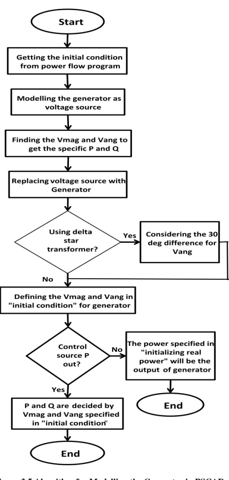
Figure 3.5 Algorithm for Modelling the Generator in PSCAD ... 54
Figure 3.6 Two-area Test Network ... 55
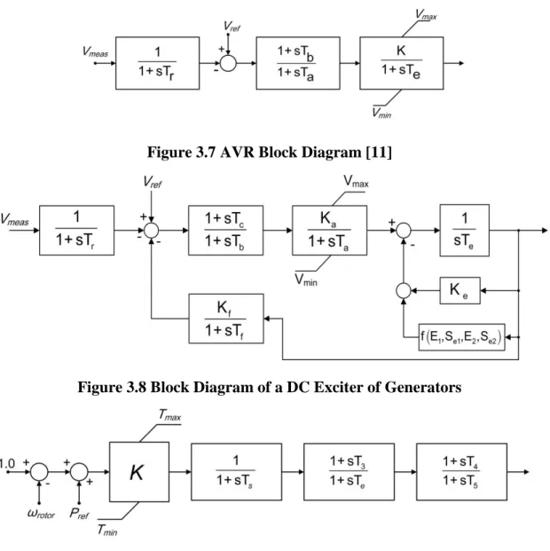
Figure 3.7 AVR Block Diagram ... 56
Figure 3.8 Block Diagram of a DC Exciter of Generators ... 56
Figure 3.9 Governor Block Diagram ... 56
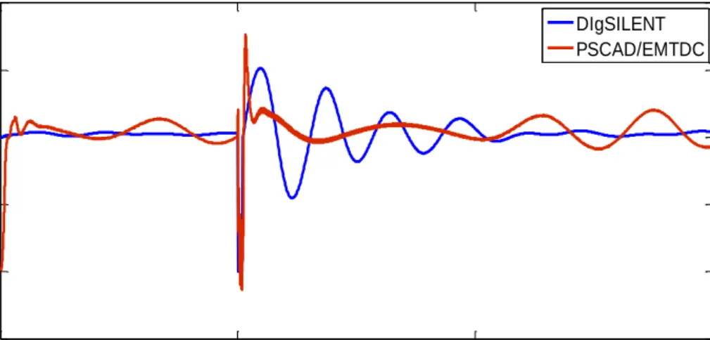
Figure 3.10 Active Power Flow Results in PSCAD/EMTDC and DIgSILENT... 58
Figure 3.11 Reactive Power Flow Results in PSCAD/EMTDC and DIgSILENT ... 58
Figure 3.12 Voltage Magnitude Results in PSCAD/EMTDC and DIgSILENT ... 58
Figure 3.13 Active Power Flow at Line 3 ... 59
Figure 3.14 Voltage Magnitude at Busbar3 ... 59
Figure 3.15 Representative GB Transmission Network ... 60
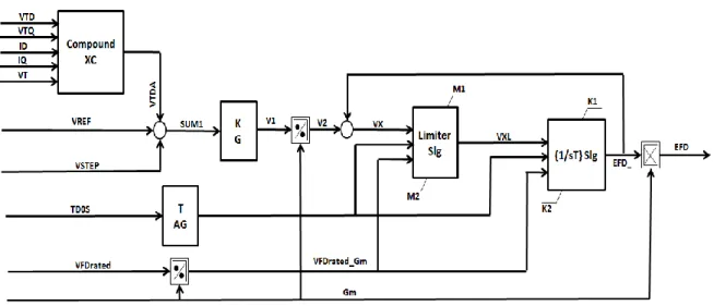
Figure 3.16 The AVR Model in DIgSILENT ... 61
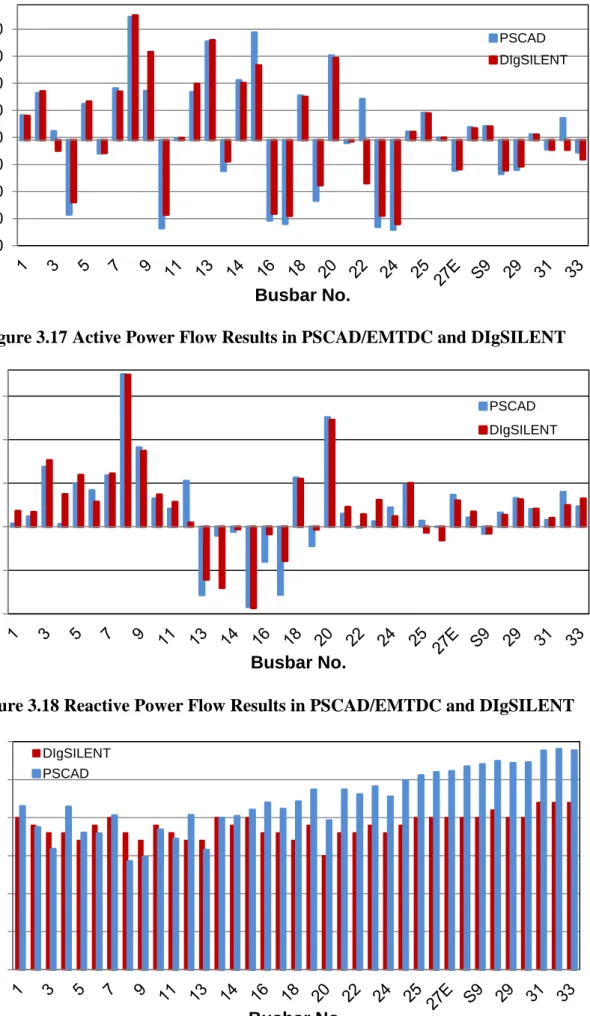
Figure 3.17 Active Power Flow Results in PSCAD/EMTDC and DIgSILENT... 63
Figure 3.18 Reactive Power Flow Results in PSCAD/EMTDC and DIgSILENT ... 63
Figure 3.19 Voltage Magnitude Results in PSCAD/EMTDC and DIgSILENT ... 63
Figure 3.20 Voltage Magnitude at Zone 1 ... 64
Figure 3.21 Active Power Flow for G2 (Nuclear Generator) at Zone 1 ... 65
Figure 4.1 Schematic of the Two-Area Four-Machine System ... 72
Figure 4.2 Schematic of the Two-Area Four-Machine System Connected with an HVDC Transmission Link. ... 75
Figure 4.3 Comparison of Oscillatory Modes in the Test Systems with and without HVDC. ... 78
Figure 4.5 Two-area Test Network Including Embedded VSC-HVDC Line ... 86
Figure 4.6 Oscillatory Modes in the Test System. ... 86
Figure 4.7 Probabilistic Inter-area Mode Locations for the Test System ... 88
Figure 4.8 Histogram of the Distribution for Critical Modes Damping (Upper) and the Real Part (Lower) for Modes Numbers 1, 2 and 3 using MC ... 89
Figure 4.9 PDFs of 𝝈𝒄𝒓𝒊𝒕 and 𝜻𝒄𝒓𝒊𝒕 Produced for 24% Input Certainty for Critical Mode Damping (Upper) and Real Part (Lower) for Modes Numbers 1, 2 and 3 ... 91
Figure 4.10 cdfs of 𝝈𝒄𝒓𝒊𝒕 and 𝜻𝒄𝒓𝒊𝒕 Produced for 24% Input Certainty for Critical Mode Damping (Upper) and Real Part (Lower) for Modes Numbers1, 2 and 3 ... 92
Figure 5.1. An Overview of the N4SID System Identification Process………..94
Figure 5.2 Schematic of the Two-area Four-machine System Connected with an HVDC Transmission Link . ... 95
Figure 5.3 The Injected Signal for System Identification at the HVDC Current Set-point ... 96
Figure 5.4 The Resulting Rotor Oscillations by Injecting a PRBS Signal ... 96
Figure 5.5 . Comparison of the Identified Models with the Original Model ... 98
Figure 5.6 Model Order Selection ... 99
Figure 5.7 The Response of the Estimated and Actual Model ... 100
Figure 5.8 Frequency Response Comparison of the Original and Reduced Models .... 101
Figure 5.9 Standard MLQG Controller Structure ... 103
Figure 5. 10 Standard MPC Controller Structure ... 106
Figure 6.1 Schematic Diagram of the Two-area Four-machine System Connected with an HVDC Transmission Link ... 110
Figure 6.2 Feedback Control for Single Input ... 112
Figure 6.3 Parameters of the Designed MLQG ... 113
Figure 6.4 LTR Procedure at Plant Inputs with Various Values of q ... 114
Figure 6.5 Parameters of the Designed MPC ... 115
Figure 6.6 The System Poles with and without Controllers ... 116
Figure 6.7 Active power Flow on HVDC Link ... 118
Figure 6.8 Active Power Flow on Line 3 ... 118
Figure 6.9 Generator2 Speed ... 118
Figure 6.10 Generator4 Speed... 119
Figure 6.11 Output Control System Signal ... 119
Figure 6.12 Input Control System Signal ... 119
Figure 6.14 Probabilistic Inter-area Mode Locations for No POD Controller (top),
MLQG Controller (middle), MPC Controller (bottom) ... 122
Figure 6.15 Boxplot for the Damping of the Inter-area Mode ... 123
Figure A. 1 Schematic of the Two-area Four-machine System Connected with an HVDC Transmission Link. ... 145
Figure A. 2 Block Diagram of DC Exciter of G1, G3 and G4 ... 146
Figure A. 3 Block Diagram of Static Exciter of G2. ... 147
Figure A. 4 Block Diagram of Speed Governor of G1, G2, G3 and G4. ... 147
Figure A. 5 Rectifier’s α Control for Constant Current. ... 149
Tables
Table 3.1 Summary of Software Comparison ... 49
Table 4.1 Power Flow and Voltage Magnitude for System without HVDC ... 72
Table 4.2 Eigenvalues of Test System without HVDC ... 73
Table 4.3 Observability Factor for Eigenvalue 1 (Inter-area Mode) ... 74
Table 4.4 Controllability Factor for Eigenvalue 1 (Inter-area Mode) ... 74
Table 4.5 Participation Factor for Eigenvalue1 (Inter-area Mode) ... 74
Table 4.6 Power Flow and Voltage Magnitude for System with HVDC... 75
Table 4.7 Eigenvalues of Test System with HVDC ... 76
Table 4.8 Observability Factor for Eigenvalue 3 (Inter-area Mode) ... 76
Table 4.9 Controllability Factor for Eigenvalue 3 (Inter-area Mode) ... 77
Table 4.10 Participation Factor for Eigenvalue 3 (Inter-area Mode) ... 77
Table 4.11 Oscillatory Modes in Test System ... 87
Table 4.12 Moment of Mode Damping ... 90
Table 4.13 Moment of Mode Damping Ratio ... 91
Table 5.1 Measured and Simulated Model Output Fitness (%) ... 97
Table 6.1 Electromechanical Mode Properties for Two Area Test System with an Embedded LCC-HVDC Link ... 111
Table 6.2 MLQG Controller Design Parameters ... 114
Table 6.3 MPC Controller Design Parameters ... 116
Table 6.4 Electromechanical Mode Details for the Test System ... 117
Table 6.5 Settling Time for the Test System... 120
Table 6.6 Damping Ratio and Frequencies of Critical odes ... 124
Table A.1 Synchronous Machine Parameters of G1, G2 and G3 and G4. ... 132
Table A.2 Power Generation Conditions of G1, G2 and G3 and G4. ... 133
Table A.4 Parameters of DC Exciter... 133
Table A.5 Parameters of Static Exciter. ... 134
Table A.6 Parameters of Speed Governor... 134
Table A.7 Transformer Parameters. ... 134
Table A.8 AC Transmission Line Parameters... 135
Table A.9 DC Transmission Line Parameters... 135
Table A.10 Parameters of Rectifier Control. ... 136
Table A.12 Load Data. ... 136 Table A.13 Shunt Capacitors. ... 136
List of Abbreviations
AC Alternating Current
ARE Algebraic Riccati Equation
AVR Automatic Voltage Regulator
CPU Central Processing Unit
DC Direct Current
FACTS Flexible AC Transmission System
GPS Global Positioning System
HVDC High Voltage Direct Current
IEEE Institute of Electrical and Electronic Engineers
IGBT Insulated gate bipolar transistor
LCC line commutated converter
LDS Low Discrepancy Sequences
LMI Linear Matrix Inequality
LQG Linear Quadratic Gaussian
LQR Linear Quadratic Regulator
LTR Loop Transfer Recovery
MC Monte Carlo
MIM Multiple-Input-Multiple-Output
MISO Multiple-Input-Single-Output
MLQG Modal Linear Quadratic Gaussian
MPC Modal Predictive Controller
MTDC Multi-Terminal Direct Current
NGET National Grid Electricity Transmission plc
ODIS Offshore Development Information Statement
OPF Optimal Power Flow
PC Personal Computer
PDC Phasor Data Concentrator
PDF Probability Density Function
PEM Point Estimated Method
PI Proportional-Integral (Control)
PLF Probabilistic Load Flow
PMU Phasor Measurement Unit
POD Power Oscillation Damping
PSS Power System Stabiliser
PV Power–Voltage
SISO Single-Input-Single-Output
SSR Sub-Synchronous Resonance
SVC Static Var Compensator
TCSC Thyristor Controlled Series Capacitor
TGR Transient Gain Reduction
TPE Two Point Estimate
UK United Kingdom
USA United States of America
VDCOL Voltage Dependent Current Order Limiter
WAC Wide Area Controller
List of Symbols
α Firing angle
β Inverter angle
Set of uncertain system parameters
Extinction angle/Uncertain system parameter
Generator rotor angle
Error
Modal damping ratio
Voltage angle
Complex eigenvalue
Mean
Modal damping (real part)/Standard deviation
Signal transmission delay
Power angle/Weibull scale parameter
Generator flux linkage/Left eigenvector
Speed/Modal frequency (imaginary part)
Right eigenvector
a Recursive coefficient
b Recursive coefficient
c Calculation constant
k Weibull shape parameter
m Number of power system inputs
n Converter transformer turns ratio/Number of/Power system order
p Number of power system outputs
r Rank index
t Time
u Controller output signal (power system input)
x System state
y Controller input signal (power system output)
z Modal system state
B Susceptance
C Capacitance
D Generator damping constant
E Voltage
G Active power output from a generator
H Generator inertia constant
I Current
K Controller gain
L Inductance/Active power demand at a load
P Active power
R Resistance/system transfer function residue
T Time constant
X Reactance
Y Admittance
Subscripts
0 Initial values/equilibrium point
1, 2, 3, 4 Various controller constants
1d Effective d-axis (mathematically defined parameter)
2q Effective q-axis (mathematically defined parameter)
c Complex eigenvalue pairs
comp Compensation
conv HVDC converter
d-axis Machine reference frame
dc DC system parameter
e Generator electrical output
eq Equivalent
ex Excitation system
f Excitation field
i Index value, where i =1, 2, 3…
inv Inverter
j Index value, where j =1, 2, 3…
lk Leakage
m Generator mechanical input
marg Margin
o Open-circuit
q-axis Machine reference frame
r Generator rotor/real eigenvalues
rect Rectifier
s Generator stator
syn Synchronous
t Generator terminal
A, B, C, E Various controller constants
C Shunt capacitor (load flow)/commutating
D-axis System reference frame
G Generation (load flow)
I Integral
N Number of buses within a power system
P Proportional
POD Power oscillation damping controller
PSS Power system stabiliser
Q Q-axis System reference frame
R Transducer delay
Superscripts
. Derivative ˆ Estimate ' Transient '' Sub-transient conv HVDC converter ex Excitation system inv Inverter load Loadmax Maximum limit
min Minimum limit
rect Rectifier
red Reduced
ref Reference set-point
sys AC power system
Idc DC current
MLQG Modal linear quadratic Gaussian controller
Pdc DC active power injection
Qdc DC reactive power injection
T Matrix transpose
TGR Transient gain reduction
Tx Transformer
Vdc DC voltage
1
Chapter 1
Introduction
In order to reach the EU and UK governments’ targets for the decarbonisation of greenhouse gas emissions, reinforcement of Great Britain’s power electricity system will be required involving some significant changes [1]. In particular, following this reinforcement, a large capacity of wind generation will have a major effect on the future operation of the GB transmission system. Consequently, there will be a requirement for additional transmission capacity to be deployed within the existing AC transmission system. Hence, more transmission technologies, such as embedded HVDC links and series compensation, will be introduced into the GB transmission system in future [2]. The flexibility and controllability of these FACTS devices will provide further benefits with respect to power system operations, including power system stability.
On the other hand, increasing the capacity of wind generation and transferring electrical power across long distances will increase the level of stress in the power system operating conditions [3], which could easily lead to the onset of stability problems. Among the stability issues in large interconnected power systems, lightly damped inter-area oscillations play the most important roll [3].
This research has been carried out in order to gain a greater understanding of the performance of embedded High Voltage Direct Current (HVDC) systems, aimed at the improvement of system stability and also greater effectiveness of the control systems in maintaining power system stability.
1.1
The GB Transmission System
The legally binding target to reduce greenhouse gas emissions is at least 80% below the 1990 level by 2050 [2] and the UK Government is dedicated to meeting it. In order to
do so, the government has committed itself to ensuring that 15% of the UK’s energy demand will be produced by renewable sources by 2020 [2]. It is expected that wind generation will significantly increase and reach approximately 20 GW by 2020, moving up to 59.2 GW by 2035 [2], [3]. The impact of this target on the future generation mix in the UK can be seen in Figure 1.1. Also the impact of this scenario on the generation mix up to 2035 can be seen in Figure 1.2.
Figure 1.2 Gone Green Generation Background [186]
In order to increase the capacity of the GB transmission system, the electricity transmission network in GB (England and Wales) is connected to the Scottish Power Transmission network through two double 400 kV AC circuits. Also, there are HVDC interconnections to France, the Netherlands, Northern Ireland and Ireland [1].
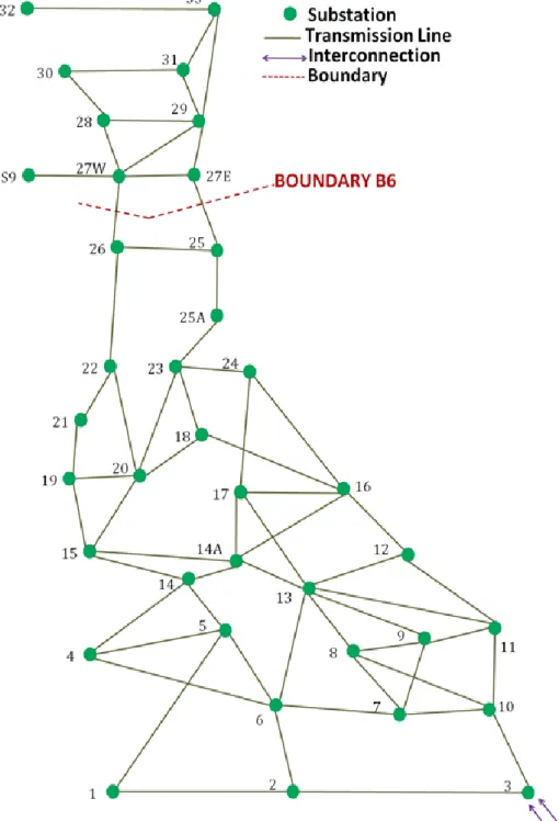
Figure 1.3 summarises the proposed locations of the TCSC and the new HVDC link, which is the prototype of the GB future electric power transmission network (vision 2020/2030) [4, 5].
In this system, the majority of generation is in the North with the largest demand centre being in the South East. Consequently, this will lead to a significant increase in the power transfer capability requirement across the Anglo-Scottish boundary (B6 boundary) and make this boundary the main area of concern in terms of stability of the
system [1, 2]. The existing inter-area mode between the generators in Scotland and those of England & Wales has been identified at around 0.5 Hz [1], [6]
In increasing volumes of renewable generation and providing more connectivity between England and Scotland, the ability to manage this boundary effectively will become ever more important [1].
1.2
Power System Stability
Power system stability has been known to be an important issue for secure systems operation since the 1920s [7], [8] . Many major blackouts owing to power system instability have proved the salience of this phenomenon [7], [9].
Power system stability refers to the capability of an electrical power system to maintain stable operation during normal conditions. Also, it is necessary to have the capability to return to a suitable stable operating point with an acceptable time after disturbances have happened [10] , [11]. A large sized power system has greater risk of being subjected to large disturbances than smaller ones. These can be faults, load changes, generator outages, line outages, voltage collapse or some combination of these and the system must be capable of responding to them without failure. Under such circumstances, the remaining power system equipment should resume stable operation quickly, which is achieved by the operation of protection devices to remove the faulty component from the network [10].
Power system stability issues can be generally classified as follows [10], [11] :
Rotor Angle Stability: the capability of the interconnected generators within the power system being at the same frequency in order to maintain synchronous operation;
Voltage Stability: the capability of keeping acceptable voltages at all system buses [10];
Frequency Stability: the capability of a power system to maintain steady frequency following a severe disturbance between generation and load.
It should be noted that rotor angle, voltage and frequency stability are not independent isolated events. For instance, a voltage collapse at a bus is going to lead to large trips in rotor angle and frequency. Likewise, a large frequency deviation is going to lead to large changes in voltage magnitude [11].
Each of these three stabilities can be further classified into large or small disturbances, i.e. short term or long term [11].
1.2.1 Power System Oscillations
Electro-mechanical oscillations between interconnected synchronous generators are phenomena characteristic to power systems. Generally, in a stable system, if the rotor of one machine deviates from its synchronous speed, the distribution of power generation will act to reduce this deviation [10], [12], which is associated with the remaining generators and the installed system controllers [10], [12]. In this circumstance, the retuning of the system to equilibrium is going to lead to mechanical oscillations. The effect of these can be seen as variations in the electrical output of the machine in terms of electrical power and voltage [10]. The stability of these oscillations is of fundamental concern and must be damped effectively so as to maintain secure and stable system operation.
The capability of synchronous machines of an interconnected power system to remain synchronised following small changes (small disturbances) is known as small signal stability (or small-disturbance). On the other hand, transient (or large disturbance) stability analysis is concerned with the response of the power system after large transient disturbances. The time scales can range from milliseconds (small disturbance) to a few seconds at most (large disturbance) [10], [11].
The work presented in this thesis is mainly focussed on large-disturbance stability analysis of power systems through investigating the time-varying performance of the network in the presence of HVDC links and controllers.
Electromechanical oscillations for power systems have varying reasons and these oscillatory modes can be classified as follows [10], [11].
Torsional Modes: the frequency for these modes is between 5 and 50 Hz. These are associated with oscillations, which are caused by the rotational components in the turbine-generator shaft system [10].
Control Modes: typically the frequency of these modes is less than 0.1 Hz. These are added to the system by installing the controllers within it.
Local Modes: the frequency for these modes is between 1 and 2.5 Hz. These are associated with the swinging of one generator against the rest of power system.
Inter-Area Modes: the frequency for these modes is between 0.1 and 1 Hz. These are generated when many machines within an area of the power system are oscillating against those in other areas of the network.
If any of these oscillatory modes mentioned above become unstable then this will lead to rising oscillations and finally, the disconnection of equipment or further cascading failures. Moreover, inter-area modes are traditionally harder to damp to compared with local ones [10] and hence, the former type in the power system provide the focus for this thesis.
1.2.2 Wide Area Measurement Systems
Wide Area Measurement Systems (WAMS) have the ability to collect data from various points. This ability provides greater observability of any inter-area oscillations within large interconnected system. In recent years, the development of WAMS has been very useful with regards to the design of complex controllers, which provide damping of critical inter-area modes [10]. With these measurement systems for collecting time-stamped data, the Phasor Measurement Units (PMUs) employed can significantly improve the damping of inter-area oscillations [10],[13],[14].
Phasor Measurement Units (PMU) are able to measure three phase voltages, magnitude and phase of currents as well as calculate time synchronised positive-sequence values. These calculations should be at rates equivalent to the power systems fundamental frequency, which is 50 Hz in the GB system. These accurate measurements make it possible to monitor the wide area snapshot of the power system in real-time and also, to track dynamic changes on the grid[1].
1.3
Overview of HVDC Development and Technologies
The classical application of an HVDC system is the transmission of bulk power with lower overall transmission cost and losses over long distances compared with the AC transmission lines. In fact, this system has emerged as the best power delivery solution in a number of situations [15], [16]. The main advantage of transferring the power with HVDC links is that the stability constraints associated with stability problems or control strategies, will not lead to limitations in the amounts of transmitted power on HVDC lines and the transmission and this constrains will be removed by interconnecting systems via HVDC lines [15], [16]. Another advantage of using HVDC links that
should be mentioned is that this system, compared with conventional AC transmission, provides a higher degree of controllability for the operation of power systems [15], [16]. Recently, installation of HVDC links in the power system has been increasing at a pace. The installed capacity of HVDC after 47 years had become 50 GW by 2001 (first commercial installation was in 1954), with just in nine years later, in 2010, it having doubled to 100 GW and it has been planned to double again by 2016 (200 GW) [10], [17].
1.3.1 HVDC Development
An HVDC link connected between two AC systems operates regardless of the voltage and frequency conditions of the two systems. Therefore, it provides an independent control for transmitting power between systems. The same applies for an HVDC link within one AC system. HVDC technology can resolve a large number of existing AC power system steady-state and dynamic instability issues and improve the security of the system. The two systems (AC and DC) can be linked together in three configurations:embedded HVDC link, HVDC grid and �DC segmentation [15].
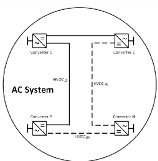
Embedded HVDC System in an AC Grid
In the first configuration, an embedded HVDC system in an AC grid, one or multiple point-to-point HVDC links are connected to the AC system buses in a single AC grid. In this configuration, the point-to-point HVDC links are used for the bulk transmission
of electrical power in a single AC grid [15]. The schematic diagram of an embedded HVDC link is shown in Figure 1.4.
Currently, The the Xiangjiaba–Shanghai is longest embedded HVDC link in the world is with 2,071 km (1,287 mi), ±800 kV, 6400 MW link connecting the Xiangjiaba Dam to Shanghai, in the People's Republic of China [15]. The longest embedded HVDC link will be the Rio Madeira link in Brazil connecting Porto Velho in the state of Rondônia to the São Paulo area. The length of this DC line will be 2,375 km (1,476 mi) [15], [17].
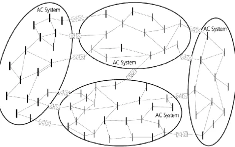
HVDC Grid
The next configuration, which will be presented in this section, is the HVDC grid. In this configuration several AC buses are interconnected within converter stations, which are the points for sharing a common DC transmission system [15], [16]. Another approach for the combination of HVDC transmission with an AC system is the meshed HVDC grid. This configuration includes multiple DC converters that are interconnected by a meshed DC transmission network. The advantage of using this approach is that if one HVDC line is lost, another will support the partially isolated node [15].
Figure 1.5 and Figure 1.6 show a schematic diagram of a meshed HVDC grid and one
of an MTDC grid, respectively. Both line-commutated current-sourced converter (LCC) and VSC technologies can be employed in an MTDC configuration, which makes it a special type of the HVDC grid [15], [16].
DC segmentation
In the third configuration, the AC grid is decomposed into sets of asynchronously operated AC segments connected through DC links [15], [18], [19] .
Figure 1.7, shows the concept of DC-segmentation. The DC links can be back-to-back (BTB) and/or PTP HVDC links [15], [19] , based on VSC and/or LCC technologies. The segments can have AC line connections as well, but these should not constitute major power corridors [15]. The size of each AC segment can be defined as a compromise between the converter cost, potential gain in reliability and power transfer capability improvement, geographical and political boundaries as well as the system operational characteristics and necessities[15] , [20].
1.3.2 HVDC Technology
There are two converter technologies available for use in HVDC transmission [10]: LCC-HVDC (Line Commutated Converter): LCC-HVDC was the first practical
HVDC conversion technology that was developed [10] and also it is the most commonly used HVDC scheme in commercial operation today [21]. This has been seen as a great technological development, mainly in terms of its switching
Figure 1.6 MTDC Technology =
components and control systems. The thyristors that are used in LCC-HVDC technology are in a Current Source Converter (CSC) topology and when the current through a thyristor is zero it will switch off. In LCC-HVDC the current always lags the voltage due to the delayed firing of the thyristors and consequently, the LCC HVDC link absorbs the reactive power. This technology is practicable for long distance transmission and large amounts of electric power at very high voltages [21], [22].
VSC-HVDC (Voltage Source Converter): Voltage Source Converters (VSC-HVDC) have been a known technology on an industrial basis for many years at a lower voltage scale. The VSC scheme uses Insulated Gate Bipolar Transistors (IGBT). At each power frequency cycle, IGBTs can be switched on and off several times by an external signal. For this technology, the reactive power is controlled autonomously and reactive compensation is not needed, which makes VSC-HVDC more controllable than LCC-HVDC. Also, this technology does not have inverter commutation failures and limited injection of low-order harmonic currents [21], [23]. Nevertheless, due to the numerous switching operations in VSC-HVDC, the losses in the converter are higher compared to LCC, which is a serious disadvantage in bulk power transmission and hence, makes it economically less interesting [21] . Another disadvantage of this technology is that VSC-HVDC cannot operate at the same power levels as the more mature LCC-HVDC [10].
1.4
Research Aim and Objectives
As aforementioned, to decarbonise UK electricity supply an unprecedented amount of change is required to the GB transmission system. Large volumes of various renewable generations that have been mentioned above are because of impact on the transmission network before 2020 [1]. To accommodate this, technologies currently unfamiliar to the GB system are being planned, including offshore embedded HVDC links and TCSC on the circuits of the prominent constraint boundary.
Majority of these changes will also be needed regarding the operational control procedures in order to secure such future transmission networks, especially in terms of stability and frequency constraints. All of these changes are becoming strongly dependent on increased information pertaining to the state of the power system [1]. This thesis aims to address many of the issues that have been identified within the current body of research. The main aim of this research are to undertake a thorough evaluation of the improvement in power system small-disturbance stability that HVDC based POD control can achieve, and to use probabilistic methods to produce a supplementary WAMS-based POD controller, which is more robust to the uncertainties inherent in modern power systems. In order to achieve this aim, the following research objectives have been defined:
1. To investigate thoroughly a suitable WAMS-based supplementary POD controller design for HVDC systems within meshed AC/DC power systems. Two control schemes have been proposed to achieve the main objective of this thesis aimed at improving the system stability by damping the oscillations.
2. To develop a methodology for probabilistically evaluating the robustness of WAMS-based supplementary POD controllers for HVDC systems with respect to uncertain power system conditions.
3. To develop appropriate measures that allow for the application of PEM for critical mode estimation within test system, which will result in fast and accurate calculation of system risk indices, such as the probability of instability.
1.5
Research Methodology
In order to achieve the aforementioned thesis objective, the following methodology is employed:
Power system modelling for two test systems,
Power system linearization for modal analysis using controllability, observability and participation factor for test system,
Stability analysis using probabilistic small disturbance stability assessment. Two methods are used, Monte Carlo Method and Point Estimated method.
Implementation of linearized state space model of the nonlinear system (using interfacing between DIgSILENT and MATLAB),
Design linear control schemes for the linearized system model (using the developed MATLAB platform) and design a control scheme based on the sensitivity of the system stability margin with respect to the parameter space, Perform time-domain simulation: DIgSILENT/PowerFactory environment is
used to evaluate the agreement between the corresponding dynamic responses of the automatically generated linearized model and the nonlinear model to small disturbances and validate the accuracy of the linearized model. The performance of the proposed control schemes (MLQG and MPC) and the dynamic behaviour of the system, including the proposed controllers, under various faults and disturbances are investigated through time domain simulations.
1.6
Main Contributions of this Research
The work in this thesis contributes to a number of areas of power systems research, specifically regarding the effects of HVDC systems on the small-disturbance stability of transmission networks. The main consequence of this research is the comprehensive probabilistic assessment of the improvement to power system small-disturbance stability that can be achieved through the use of supplementary damping control applied to HVDC systems. Assessment of the robustness of these controllers has shown the controller synthesis procedure, thus resulting in improved system performance in the presence of operational uncertainties.
To achieve the main objective of this thesis, this research work focuses on:
Developing a small-signal dynamic model. This model has been developed based on computer-assisted linearization of AC/DC systems for control design,
time-domain simulation and also the systematic performance has been evaluated for the control scheme (The developed model can be applied for various control designs and the application of this model is not limited to the controllers designed which have been used in this thesis).
Developing an HVDC supplementary control scheme, using a small signal dynamic model of the system. These supplementary controllers are developed to damp inter-area oscillations in an AC/DC system.
The development of a methodology to test probabilistically the robustness of HVDC based damping controllers, using classification techniques to identify possible mitigation options for power system operators.
The Point Estimated Method (PEM) and Monte Carlo (MC) have been developed for use in a power system to identify the statistical distributions of critical electromechanical modes in power systems in the presence of multiple operational uncertainties.
The use of a probabilistic system representation is proposed for improving POD controller performance, yielding more robust performance when considering the effects of system uncertainties. The use of the Monte Carlo Method to establish the probabilistic system demonstration results in a rapid and robust assessment of HVDC based damping controllers.
Developing a reduced model of the GB transmission system within a PSACD/EMTDC platform. The performance of the developed system was compared and confirmed with the DIgSILENT model, which was developed by the National Grid.
1.7
List of Publications
The work detailed in this thesis has resulted in number of refereed publications, as follows:
1.7.1 Journal Publications
1. Mohsen M. Alamuti, Ronak Rabbani, Shadi Khaleghi, Ahmen F. Zobaa and Gareth A. Taylor “Probabilistic Evaluation of Power System Stability Enhancement Using Supplementary Controller Schemes for an Embedded HVDC link “ Submitted to IEEE Transactions on Power System, 2015.
1.7.2 Conference Publications First Author
1. Rabbani, R.; Alamuti, M.M.; Taylor, G.A.”Investigating SVC impact at the inverter side of HVDC links for Stability Analysis of the Future Great Britain Transmission System” Power System Technology (POWERCON), 2014 International Conference, China.
2. Rabbani, R.; Mohammadi, M.; Kerahroudi, S.K.; Zobaa, A.F.; Taylor, G.A.” Modelling of reduced GB transmission system in PSCAD/EMTDC”, International Universities’ Power Engineering Conference, UPEC 2014, Cluj-Napoca, Romania.
3. Rabbani, R.; Taylor, G.A. and Zobaa, A.F., “Performance Comparison of SVC with POD and Synchronous Generator Excitation System to Investigate Oscillation Damping Control on the GB Transmission System” 48th International Universities’ Power Engineering Conference, UPEC 2013, 2-5 September 2013, DIT, Dublin, Ireland.
4. Rabbani, R., Taylor, G.A. and Zobaa, A.F., “Applications of Simplified Models to Investigate Oscillation Damping Control on the GB Transmission System ” The 10th International Conference on AC and DC Power Transmission (IET), ACDC 2012, 4-6 December 2012, Birmingham, UK.
5. Rabbani, R., Taylor, G.A. and Zobaa, A.F. “Critical Evaluation of Reduced Models for Stability Analysis on the GB Transmission System” 47th International Universities’ Power Engineering Conference, UPEC 2012, 4-7 September 2012, Brunel University, London, UK.
Co-Author
1- Alamuti, M.M.; Rabbani, R.; Kerahroudi, S.K.; Taylor, G.; Youbo Liu; Junyong Liu” A critical evaluation of the application of HVDC supplementary control for system stability improvement” Power System Technology (POWERCON), 2014 International Conference
2- Kerahroudi, S.K.; Li, F.; Bradley, M.E.; Ma, Z.; Alamuti.M.M.; Rabbani, R.; Abbod, M.; Taylor, G.A. “Critical evaluation of power system stability enhancement in the future GB transmission using an embedded HVDC link” AC
and DC Power Transmission (ACDC 2015), 11th IET International Conference on , vol., no., pp.1,6, 4-5 Feb. 2015
3- Kerahroudi, S.K.; Rabbani, R.; Fan Li; Taylor, G.; Alamuti, M.M.; Bradley, M. “Power system stability enhancement of the future GB transmission system using HVDC link”, UPEC 2014, Cluj-Napoca, Romania.
4- Alamuti, M.M.; Rabbani, R.; Kerahroudi, S.K.; Taylor, G.A. “System stability improvement through HVDC supplementary Model Predictive Control”, UPEC 2014, Cluj-Napoca, Romania.
1.8
Thesis Overview
Chapter2: Literature Review
This chapter provides past research on GB transmission system modelling of damping of power oscillations. Over the years, many studies have been carried out on stability analysis of power systems, controller designs and modelling of the GB system. These studies have been shown to be effective at damping power oscillations with various technologies, although very few have been implemented in real systems. Almost all studies are listed in this chapter.
Chapter 3: Power System Modelling and Analysis
This chapter briefly describes models of the main components of electrical power systems, which include synchronous generators, AVR and governors for generators’ transmission lines, transformers and system loads. Also In this chapter, a reduced GB system model is presented, which is based upon a future GB transmission system model and, hence, contains different types and mix of generation. This model is also based on the reduced DIgSILENT PowerFactory model developed by the National Grid and has been designed in PSCDA/EMTDC. However, the aim of this chapter is to compare PSCAD with the more widespread simulator, DIgSILENT PowerFactory.
Chapter 4: Probabilistic Small-Disturbance Stability Assessment
In this chapter, in order to analyse power system stability and design the controllers, linearization of a power system is described mathematically in a modal analysis section. This concept is described by defining parameters, including: eigenvalues, eigenvectors, participation factors, modal controllability observability and residues. Throughout this
thesis, all modelling has been designed using the DIgSILENT PowerFactory environment (version 15).
In addition this chapter presents the MC and PEM for probabilistic small-disturbance analysis. The latter significantly reduces the number of simulations needed to complete a probabilistic system assessment, whilst still accurately producing the statistical distributions of critical system modes has been saved. The method is established on a test network where it is presented to produce the statistical distributions of critical modes precisely. Following this, techniques for a reduction in the number of considered uncertainties based on eigenvalue sensitivity are proven.
Chapter 5: Damping Controller Design
The majority of power system simulation packages do not provide a model of the system in a mathematical format to the users. Since a model of the system has to be available for MPC and LQG controller design, in this chapter, the application of a system identification method to obtain an equivalent model of the system is examined. For the next step, in order to design the damping controllers, application of the POD controller designs that have been used in this thesis is provided. Also in this chapter, signal selection, system identification and order reduction are presented, which require investigation before designing the controller. The two controllers used in this thesis are modal linear quadratic Gaussian control (MLQG) and modal predictive control (MPC). Chapter 6: Application of Designed Controllers on a Test System
This chapter evaluates an approach for damping inter-area oscillations of power systems using HVDC supplementary control. The proposed supplementary controller is based on the model predictive control (MPC) scheme. To enhance the damping of inter-area oscillations in power systems, this research has designed and implemented an MPC scheme as an HVDC supplementary controller for improving AC system stability. The chapter also compares the performance of MPC with other HVDC supplementary controller strategies for improving AC system stability, such as modal linear quadratic Gaussian (MLQG) and state feedback (SF). These three approaches are tested on a two area four machine system incorporating parallel HVDC/AC transmission. The study results show the effective and superior performance of MPC for damping the oscillatory modes of the test system. Following this, a methodology for the robust probabilistic evaluation of damping controller performance is investigated. This method considers
the statistical uncertainty in system operating conditions based on the variability of loading and generation.
Chapter 7: Conclusion and Futures Work
In this final chapter a summary is provided on the work presented in this thesis outlining the specific contributions. In addition, proposals for future work are made.
Chapter 2
Literature Review
2.1
Introduction
Currently, the reliability of the electric power system in Great Britain is generally good. However, over the next few years the GB power system is going to experience a time of great change, which will result in the future GB transmission network being unique in many aspects. Large penetration of wind power with changing wind speed, direction and location will shift the concentration from one part of the system to another [24]. Consequently, this will cause of large variation in the power flow patterns in the network. In addition, the GB network will give rise to a power system with reasonably high concentration of FACTS devices, because of using several HVDC interconnections with external grids, internal HVDC transmission lines and offshore HVDC networks. These devices will bring various supplementary control features to improve the reliability and stability of the power system. However, they will bring new problems in the network [25]. Voltage stability is an important issue in an electrical power system. Consequently, several industrial grade power system simulator software packages have been developed in order to estimate the behaviour of the electric power system under certain conditions.
The inter area oscillation mode is used to define the perturbations associated with a group of generators in one area are swinging against a group of generators in another area. A large system usually involves several inter area oscillation modes. Most analyses of inter area oscillations are performed off line using system models that are
limited to individual power utilities, and do not consider the complete interconnected power system [26].
The need for improved inter-area mode damping has led to widespread research into the field of power oscillation damping. Over the years, many different controller designs have been shown to be effective at damping power oscillations with various technologies, though very few have been implemented in real systems. This chapter is going to review past research on the GB transmission system modelling and damping of power oscillations.
2.2
Past Research on GB Transmission System Modelling
System operators must address operational problems related to new generation and greater interconnection of systems. There is, however, a need to study the potential effect of new solutions carefully before committing to them and devoting important amounts of capital. These studies must be carried out via simulations using suitable models.
The GB network consists of an onshore transmission network, covering England, Wales and Scotland as well as an offshore one.
The installed capacity is predicted to increase up to 18-20 GW by 2020, compared to the current level of 12 GW, including 4.05 GW offshore [27], [28]. There will be key operational challenges for GB transmission networks, with increased wind penetration expected in Scotland. It is, therefore, planned to reinforce the GB electrical power transmission system between 2013 and 2022 [29], through the use of many more HVDC links operating in parallel with existing AC transmission routes, and also FACTS devices.
This will make the GB system operation unique and from an academic perspective an ideal choice to study power system operational challenges. However, obtaining a network model is not possible for academic research. There has been much research in this area using reduced model for the GB transmission system [30], [31], [32], [33]. Due to increasing levels of generation in Scotland, reinforcement of the Great Britain (GB) transmission network has been proposed in [30]. However, these could lead to sub-synchronous resonance (SSR). In addition in this study, the primary functions of bulk power transmission, a voltage source converter-based HVDC link has been used to provide damping against SSR, and this function has been modelled.
Belivanis and Bell in [31] are concerned with the coordinated operation of quadrature boosters (QB) installed on the high voltage electricity transmission network of Great Britain (GB). In this study, the simulation results have been conceded in MATLAB. Chondrogiannis in [32] used the average time-invariant models for the representation of Doubly-Fed Induction Generators (DFIG). This study compares the steady state and dynamic behaviour of such a model with a time variant model of the frequency converter of the DFIG, where the power electronic switches are represented. The commercial software PSCAD/EMTDC is used in this study.
[33] investigates the ability of the HVDC links to act as a firewall against perturbations. To this end, two reduced dynamic equivalent transmission systems resembling that of Great Britain are developed in DIgSILENT PowerFactory.
However, there has been little research focused on modelling a reduced model of the GB system:
Bell in [34] describes the need for new test system models to meet the needs of researchers, system planners and operators when addressing future power system requirements.
Also, in order to provide suitable environments, which are sufficient for testing new ideas and that allow for the study of phenomena without overwhelming the researcher with excessive data or obscuring what is relevant, a new model to represent the GB transmission system has been developed to facilitate this by Belivanis and Bell in [35].
It should be noted that all the explained models have been created in a DIgSILENT PowerFactory environment.
2.3
Past Research on Damping of Power Oscillations
Due to changing generation patterns and increase in demand, power system operators will need to operate transmission systems much closer to the stability limits than was done previously. Supplementary and wide-area control of flexible AC transmission system (FACTS) devices can be employed to ensure stable operation of a power system closer to its capacity limits. When implemented correctly, supplementary controllers can change the momentary flow of active or reactive power, or the local voltage, so as to improve system stability. Two general methods of improving power system stability are installing new devices and improving the control of existing ones. In particular, the
following methods for improving power system stability have been investigated in the literature.
2.3.1 Installing New Infrastructure:
This includes adding new transmission lines to the power system or installing new generation capacity [36].
2.3.2 Installing Flexible AC Transmission System (FACTS) Controllers
There has been wide-ranging research [13, 37-51] on the use of power oscillation damping (POD) controllers installed with FACTS devices. The basis of this research lies in the use of various techniques for designing controllers that cover a wide variety of device types. These FACTS devices could be rendered more effective by connecting series-connected devices [41, 49, 52]. In this area, the effect of a designed controller on power oscillation damping for Thyristor Controlled Switched Capacitors (TCSCs) has been investigated in [39, 42, 43, 47, 50, 51, 53-55]. In [53, 56, 57], unified power flow controllers (UPFCs) have been used. The study in [57] presents a platform system for the incorporation of FACTS devices that, due to its manageable size, permits detailed electromagnetic transient simulation. This system manifests some of the common problems that FACTS devices are used to resolve: management of congestion, improvement of stability, and voltage support. Further, the platform allows for reduced order model validation (e.g. small signal or transient stability models). Using this platform, the authors showcased the development and validation of a small signal-based model with an included UPFC and they further, successfully, used the validated model to design a feedback controller for enhanced damping. A controller has been designed for thyristor controlled phase shifting transformers in [53], thyristor controlled series capacitors (TCSCs) in [53-55], static VAR compensators (SVCs) in [58-60], static phase shifters (SPSs) in [60] , and static synchronous compensators (STATCOMs) in [61] . Noroozian and Angquist in [53] investigate the enhancement of power system dynamics and analyse models appropriate for integration in dynamic simulation programs to study voltage angle stability. Deriving a control strategy for damping electromechanical power oscillations with an energy function method, the authors show that the control laws thus achieved are effective for the damping of both large-signal and small-signal disturbances. Moreover, they are also robust in respect of the loading condition, fault location and network structure. The authors also establish that the
control inputs can be derived conveniently from locally measurable variables. The effectiveness of such controls have been demonstrated for model power systems.
Arabi and Rogers in [58] discuss about the DC link and SVC model formulation and their controllers for ensuring small-signal stability in detail. The authors present several cases to demonstrate the ability and application of small-signal DC link and SVC models, and to verify small-signal results through time-domain simulation results. They establish that modes obtained by spectral analysis of the time simulation results closely approximate those obtained by small-signal stability analysis.
Iravani and Dandeno in [60] evaluated additional functions for a static phase shifter (SPS) with respect to the performance of a power system in (a) steady-state conditions, (b) small-signal dynamics and (c) large-signal dynamics. They used eigenvalue analysis as well as AC-DC transient stability and power flow programs to study four test systems exhibiting the following operational issues that are endemic to power systems: torsional oscillations, inter-area oscillations, transient instability and mechanical torques as well as the loop-flow phenomenon. The results were promising and demonstrated that, under the right conditions, an SPS could effectively function as mitigator of small-signal oscillations or an enhancer of transient stability, in addition to its usual function of steady-state power flow regulation. The results further indicated that it was feasible to achieve the most dynamic characteristics of an SPS by adding a small static power converter to a conventional phase-angle regulator.
Further, Patil and Senthil in [61] present findings from a study on the application of the static compensator (STATCOM), a recently developed FACTS device, as a torsional oscillation dampener in series-compensated AC systems, considering the IEEE first benchmark model. In the study, a STATCOM with a PI controller (for regulation of bus voltage) and a generator speed-derived auxiliary signal was utilized at the generator terminal to dampen torsional oscillations. The analyses undertaken included eigenvalue (for small value analysis) and step response analysis (to generate optimal control system parameters). Once the STATCOM controlled was thus optimized, the authors also assessed the dynamic performance of the nonlinear system under a three-phase fault. The findings were promising and indicated that an optimized STATCOM could be technically feasible as a dampener for turbine-generator torsional oscillations in series-compensated AC systems. However, in many power systems, shunt-connected devices, such as SVCs, have been installed to provide voltage support. Power oscillation
damping applications for these devices have been studied in [13, 37, 44, 46, 58, 59], whereas the combination of series- and shunt-connected devices has been investigated in [38, 40, 45, 48].
In much of the previous work into FACTS-based POD control, WAMS-based global signals have been exploited to improve system observability and modal damping [13, 37, 39, 40, 42, 50, 51] . Research has also been conducted on the most suitable signals for POD in [62-64], taking into account not only the signal content, but also the reliability and robustness of the content. In [51], the authors describe the disadvantages involved in applying the LTR (Loop Transfer Recovery) technique for reserving the robustness of the LQG damping controller. They use nonlinear power system simulation to verify the robustness of the designed controller, thereby demonstrating its effectiveness for damping power system oscillations. However, many studies cite the need for robust decentralised control, utilising only those signals that are locally available at the FACTS installation [38, 41, 43-49, 52] . In [52], the principal study objective is the identification of optimal control laws and the locations of series-connected FACTS controllers (such as TCSC and SSSC) in a unified framework for damping power swings. For the study, a circuit analogy of the electro-mechanical system is employed to identify the control laws, proposes a location index, and also posits that the signals can be synthesized with locally available measurements. The validation of the technique was undertaken on detailed models of 3-machine and 10-machine systems. The authors found that it is possible to achieve good damping factors, although performance is rendered heavily dependent on installed device location and signal availability, both of which cannot be easily controlled in practical installations, particularly where devices are not primarily installed for POD purposes.
The literature outlines a variety of controller synthesis techniques, ranging from extensions of traditional linearisation-based residue techniques that incorporate global signals [13, 50] to the novel use of fuzzy control laws [41]. There are several well-established analysis and design techniques for linear time-invariant (LTI) systems. These linear design and analysis methods cannot always be applied directly without alteration, since the inherited nature of power systems yields nonlinear dynamics for large disturbances. Lyapunov’s direct method plays a pivotal role in the stability study of nonlinear control systems. This technique is based on the existence of a scalar function of the states. This function decreases monotonically along the trajectories to
![Figure 1.3 summarises the proposed locations of the TCSC and the new HVDC link, which is the prototype of the GB future electric power transmission network (vision 2020/2030) [4, 5]](https://thumb-us.123doks.com/thumbv2/123dok_us/10181433.2920574/22.892.242.733.511.1095/figure-summarises-proposed-locations-prototype-electric-transmission-network.webp)