Energy-Efficient Infrastructure Formation in MANETs
Ahmed Safwat and Hossam Hassanein
Hussein Mouftah
Telecommunications Research Laboratory
Department of Computer Science
Queen’s University
Kingston, ON, Canada K7L 3N6
{safwat, hossam}@cs.queensu.ca
Department of Electrical & Computer Engineering
Queen’s University
Kingston, ON, Canada K7L 3N6
[email protected]
Abstract
In this paper, we propose a novel protocol for wireless mobile ad hoc networks, which establishes a dynamic wireless mobile infrastructure. The proposed protocol, namely, the Power-Aware Virtual Base Stations (PA-VBS) protocol, mimics and maintains the operation of the conventional fixed infrastructure in cellular networks. In the PA-VBS protocol, a mobile node is elected from a set of nominees to act as a temporary base station within its zone based on its normalized power value. Likewise, we study the characteristics and performance of PA-VBS by means of simulation. It is shown that PA-VBS scales well to large networks of mobile stations, and that it outperforms other infrastructure-formation protocols in terms of load balancing.
1. Introduction
An ad hoc, or multi-hop, mobile wireless network, is a collection of wireless mobile stations forming a temporary network without the aid of any centralized administration. In such an environment, it may be necessary for one mobile host to use the others in forwarding a packet to its destination, due to the limited propagation range of each mobile host’s wireless transmissions. Therefore, some form of routing protocol is necessary, since two hosts that may wish to exchange packets might not be able to communicate directly. The routing problem in ad hoc networks is complicated since any, or all, of the hosts involved may move at any time.
Table-driven routing protocols [1-2] incur extensive bandwidth and computation overhead in the presence of mobility. Therefore, a number of on-demand routing protocols [3-5] have been proposed for wireless mobile ad hoc networks. On-demand routing has two major components: route discovery and route maintenance. The route discovery function requires a
source to use some form of flooding. The transit nodes, upon receiving a query, “learn” the path to the source and enter the route in their forwarding tables. The destination node responds using the path traversed by the query. A route can then be established between source and destination. Route maintenance is responsible for reacting to topological changes in the network, and its implementation differs from one algorithm to the other. On-demand routing algorithms include ad hoc on demand distance vector routing (AODV) [3] and dynamic source routing (DSR) [4]. However, in such protocols, route discovery and maintenance may become inefficient under heavy network load, where large queuing delays contribute to increasing the probability of node mobility, and hence lead to route breakages.
In view of the foregoing, developing an infrastructure for the infrastructure-less wireless mobile ad hoc networks is of utmost importance. Such an infrastructure reduces the problem of wireless mobile ad hoc communications, from a multi-hop problem, to a single-hop problem, as in conventional cellular communications. The previous apprehension originates from the intuitive realization of the problems of medium access and routing in wireless mobile ad hoc networks and their effects on QoS-guaranteed communications. Such a dynamic infrastructure will form the basis for developing MAC protocols and routing algorithms, which can utilize it to conform to the different QoS requirements. Infrastructure-based wireless mobile ad-hoc communications will help circumvent routing and medium access control issues. Therefore, in this paper, a wireless mobile infrastructure is developed for ad-hoc networks. We propose an infrastructure-creation protocol for wireless mobile ad-hoc networks, namely, the Power-Aware Virtual Base Stations (VBS)
protocol. Nevertheless, the developed infrastructure is, essentially, a mobile infrastructure. The proposed infrastructure-formation scheme demonstrates quick
response to topological changes in the ad hoc network. Additionally, the protocol is scalable to networks with large populations of mobile stations. It outperforms current infrastructure-creation schemes in stability and load balancing among the mobile stations forming the infrastructure.
This paper is organized as follows. The next section discusses existing infrastructure-creation protocols in wireless mobile ad hoc networks. In Section 3, the PA-VBS protocol is described in detail. A performance evaluation of the protocol is given in Section 4. Finally, Section 5 presents the conclusions drawn from the paper.
2. Previous Work
Recently, there has been interest in hierarchical architectures for ad hoc networks [6-9]. A mobile infrastructure is developed in [6] to replace the wired backbone infrastructure in conventional cellular networks. Moreover, an adaptive hierarchical routing protocol is devised. The routing protocol utilizes the mobile infrastructure in routing packets from a source mobile terminal (MT) to a destination MT. The algorithm divides the wireless mobile ad-hoc network into a set of clusters, each of which contains a number of MTs, which are at most two hops away. Clusters have no clusterheads, instead they are only a logical arrangement of the nodes of the mobile network. Instead, a cluster centre node is chosen. Cluster centres ensure that the distance between any two nodes in any cluster is at most two hops. The node with the highest connectivity is chosen to be the centre of the cluster. This, in fact, introduces a major drawback to the stability of the various clusters since with high-mobility, cluster re-formations frequently take place due to the continuous random movements of MTs.
In [7], the Random Backbone (RB) algorithm is developed using a Random Network Model (RNM) that was created to deal with the probabilistic nature of mobile systems. The method accounts for potential co-relations among mobile terminals. The concept of Virtual Cellular Architecture (VCA) is introduced. The algorithm requires that the clusterheads form a dominant independent set in the network graph. RB is used to derive a solution for the basic problem of connecting the clusterheads into a virtual backbone. Connections between nearby clusterheads are established, without the knowledge of the global network topology. The goal of this scheme is to come up with a virtual backbone (VB) that connects all
clusterheads via appropriate connections so that the backbone forms a connected graph.
A heuristic, called max-min, is proposed in [8] for solving the problem of forming a minimum d-hop dominating set of clusterheads. Each run of max-min uses 2d rounds of flooding to propagate node ID’s from any mobile station to its d-hop neighbors. At the end of the 2d rounds, each node either declares itself a clusterhead, or elects another MT as the clusterhead. Max-min provides an optimal solution only when the mobile stations with the largest node ID’s are spaced d hops apart; a condition which cannot be guaranteed in a dynamic environment such as that of an ad-hoc network.
The least cluster change algorithm (LCC) [9] elects MTs as clusterheads based on their ID numbers. The nodes with the lowest ID numbers win. Clusterhead changes take place when two clusterheads come within the wireless range of each other. When a node is disconnected from any other cluster it becomes a clusterhead as well.
In the virtual base stations (VBS) protocol proposed in [10], MTs are also elected as clusterheads based on their ID numbers. However, and unlike LCC, the VBS protocol puts more emphasis on a node becoming a clusterhead, or a VBS, rather than being supervised by one. Hence, if a node receives a merge request, it responds by sending an accept-merge message, even if it was being supervised by a VBS. Moreover, it is noteworthy that this neither degrades intra-cluster nor inter-cluster communications by any means. If the node that became a VBS was originally acting as a gateway for its previous VBS, it will still be a gateway, besides being a VBS. This becomes of great significance if the criterion upon which VBSs were elected was one that relies on the assets possessed by the MTs of the ad hoc network. Processing speed, main and secondary storage, and MAC contention experienced in the neighborhood of the MT can be amongst such assets. Consequently, if an MT chooses not to become a clusterhead, only because it is under the supervision of another MT, even though it possesses the required assets to become one, the node requesting to merge might experience demoted communications to other nodes in the ad hoc network because it does not have the proper resources, nor is it able to be associated with a VBS. Clusterhead gateway switch routing (CGSR) [9], as opposed to VBS, requires all the nodes in the ad hoc network to maintain routing information about each and every other node in the network, not to mention the other
pitfalls of this scheme; one example is the problem of pseudo links in CGSR.
3. The Power-Aware Virtual Base Stations
(PA-VBS) Protocol
An overview of the proposed PA-VBS scheme is presented in Section 3.1. Moreover, a detailed description of the protocol, including the pseudo code of the algorithms that are of special importance to the operation of PA-VBS, is provided in Section 3.2. This is also in addition to the finite state machine describing the protocol, and its accompanying state transition table.
3.1. Overview of The Scheme
In our scheme, some of the MTs, based on their current residual battery capacity, become in charge of all the MTs in their neighborhood, or a subset of them. This can be achieved by electing one to be a Power-Aware Virtual Base Station (PA-VBS). If a VBS moves or stops acknowledging its presence via its periodic beacons, also called hello messages, for a period of time, a new one is elected. Electing a single VBS from a set of nominees is done in an efficient way. Every MT has a sequence number that reflects the changes that occur to that MT. Sequence numbers are not only used for the sake of taking proper routing decisions, as in the case of the VBS protocol, but are also used to save battery power whenever possible. In addition to the sequence number, a myVBS variable is used to store the ID number of the VBS in charge of that MT. If an MT has a VBS, its myVBS variable will be set to the ID number of that VBS, else if the MT is itself a VBS, then the myVBS variable will be set to 0, otherwise it will be set to –1.
MaxPoweri (MPi) is defined as the battery capacity whose value is in one-to-one correspondence with the amount of time in seconds that MTiwhen used by a class-1 user, would last, starting from the time it had a fully charged battery, without having to be re-charged, provided that (1), (2), and (3), below are true.
(1) It remains a class-1 user during the whole MPi period
(2) It does not become a VBS during the whole MPi period
(3) It has inactive neighbors during the whole MPi period.
Likewise,MAX_POWER is a constant defined as the minimum required battery capacity for a class-1 user’s
MT to last, starting from the time it had a fully charged battery, for exactly one day without having to be re-charged, provided that the following are true:
(1) It remains a class-1 user during the whole one-day period
(2) It does not become a VBS during the whole one-day period
(3) It has inactive neighbors during the whole one-day period
Besides, NormalizedMaxPoweri (NMPi) is equal to MPi / MAX_POWER. Hence, NMPi can be equal to 1 only when MPi is equal to MAX_POWER. The current NormalizedPowerValue for MTi, NPVi, is equal to the instantaneous battery capacity of MTi, divided by MAX_POWER.
As will be explained in Section 4, PA-VBS facilitates load balancing between the wireless nodes. This is largely due to the fact that PA-VBS takes the nodal activity of the MTs a VBS is in charge of into account when calculating the amount of consumed power. An MT is chosen by one or more MTs, to act as their VBS based on a couple of thresholds. MTs announce their NPVs in their periodic hello messages. An MT sends a merge-request message to another MT if the latter has an NPV greater than or equal to the former’s, and a predetermined threshold. The receiver of the merge-request responds with anaccept-merge
message only if its NPV is above the first threshold, namely THRESHOLD_1, at the time it receives the merge request message, in which case it increments its sequence number by 1 to reflect the change, and sets its myVBS variable to 0. When the MT receives the accept-merge, it increments its sequence number by 1 and sets its myVBS variable to the ID number of its new VBS. If an MT hears from another MT whose NPV is larger than that of its VBS, it does not send a merge-request message to it as long as its VBS’s NPV is above THRESHOLD_1. A dis-joinmessage is sent by an MT to its VBS only if the transmissions of the VBS have not been heard by the MT for some timeout period. If the VBS receives the dis-join message, it removes the sender from its list of MTs, which it is in charge of, and it increments its sequence number by one.
3.2. Detailed Description of the Protocol
In addition, this section contains the pseudo code for the algorithms that are of special importance to the operation of PA-VBS. MTs broadcast their current NPVs as part of their hello messages. Hello messages contain other useful pieces of information, such as, the
sequence number and theiAmNoLongerYourVBSflag. The iAmNoLongerYourVBS flag is used by a node acting as a VBS (see Figure 1) to convey to the MTs it is currently in charge of whether it can support them for another hello period or not. When this flag is set to false, the MTs receiving the hello message know that they will still be served by their VBS for another hello period, and therefore do not need to look for a new one for at least one more hello period. However, if that flag was set by the VBS to true, then the MTs will return to their initial state (see Figure 2). This actually takes place when the NPV of the VBS drops below the second power threshold, namelyTHRESHOLD_2. 1. if (myVBS == 0) 2. if (iAmBelowThreshold_2()) 3. N = 0; 4. cancelAllMyMTsTimers(); 5. iAmNoLongerYourVBS = true; 6. mySequenceNumber++; 7. myVBS = -1; 8. else 9. iAmNoLongerYourVBSFlag = false; 1. if ((myVBS>0) && (theSenderOfTheHelloIsMyVBS())) 2. if (iAmNoLongerYourVBS == true) 3. cancelMyVBSTimer(); 4. mySequenceNumber++; 5. myVBS = -1; 6. else 7. restartMyVBSTimer(); 8. lastPowerValueReportedByMyVBS = myVBS.normalizedPowerValue;
Upon receiving a hello message, the MT sends a merge request message to the sender, if and only if one of the following two cases is satisfied:
1. The MT is neither a VBS nor being supported by one, and the following hold:
a. Its NPV is less than the NPV of the sender of the hello message.
b. The NPV of the sender is above THRESHOLD_1.
2. The MT is currently supported by a VBS, and the following hold:
a. The last reported NPV by the current VBS is below THRESHOLD_1.
b. The NPV of the MT is less than the NPV of the sender of the hello message.
c. The NPV of the sender is above THRESHOLD_1.
The pseudo code of the algorithm executed by the MT to determine whether to send a merge request to its neighbor, upon receiving a hello message from it, is shown in Figure 3. The pseudo code shows that the MT does not send a dis-join to its current VBS. This can be explained as follows. Even though the MT sent the merge request based on the conditions listed above, this does not necessarily mean that the node receiving the merge request will accept the merge at the time the request is actually received. If the merge request was sent at time t0 when the VBS was capable of supporting the MT, it might have been received at time t1 when its NPV was below THRSESHOLD_1. 1. if (((received NPV>=THRESHOLD_1)
&& (received NPV> my NPV) && (myVBS == -1))
Figure 1: Using the iAmNoLongerYourVBS flag by a
VBS for service denial || ((myVBS>0)
&&
(lastPowerValueReportedByMyVBS< TH_1))) 2. sendMergeRequestMessageTo(senderOfHello);
Figure 3: The merge decision process
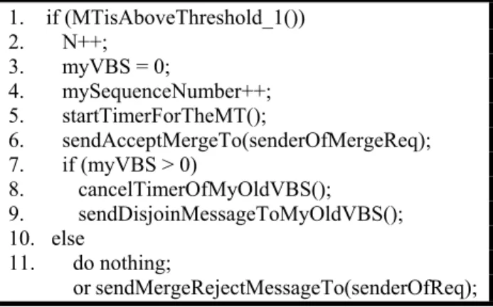
The pseudo code of the routine executed by an MT when it receives a merge request from one of its neighbors is shown in Figure 4. As stated in line 1, if and only if the receiving MT’s NPV is currently above THRESHOLD_1 will it then proceed to accept the merge request. If the condition in line 1 is satisfied, the receiver increments the number of MTs it is in charge of by 1, sets its myVBS variable to 0 to reflect that it is currently a VBS, and increments its own sequence number by 1 (see lines 2-4). In line 5, the VBS starts a timer to trigger the initiation of a timeout period. The timer is reset every time the VBS receives a hello message from the MT. If the timer expires, the VBS will no longer be in charge of the MT. This can happen if the VBS, or, equivalently, the MT, moves out of the wireless transmission range of the MT. If it happens that they become within the wireless transmission range of each other after the expiration of the timer, then the MT must send a new merge request to the VBS. The VBS may then accept or reject the merge request based on its NPV at the time of the reception of the merge request. If the receiver of the merge request was not responsible for any other node
Figure 2: Using the iAmNoLongerYourVBS flag by an MT to detect service denial
at the time the merge request was received, and was being supported by another node acting as its VBS, then it cancels the timer corresponding to its VBS, and sends a dis-join message to it (lines 7-9). In the case where a node is incapable of serving a neighbor, PA-VBS supports two means of notifying an MT of a rejected merge request. The first is an implicit merge reject method where the MT assumes that its merge request was rejected if it does not receive anything back from the VBS. The other method relies on sending a merge reject message back to the MT informing it that its request cannot be supported (line 11). The implicit merge reject method can be utilized in highly congested zones, while merge reject messages can be used otherwise.
1. if (MTisAboveThreshold_1()) 2. N++; 3. myVBS = 0; 4. mySequenceNumber++; 5. startTimerForTheMT(); 6. sendAcceptMergeTo(senderOfMergeReq); 7. if (myVBS > 0) 8. cancelTimerOfMyOldVBS(); 9. sendDisjoinMessageToMyOldVBS(); 10. else 11. do nothing; or sendMergeRejectMessageTo(senderOfReq);
When an MT receives an accept-merge message it performs the algorithm in Figure 5. The receiver sends a disjoin message back to the issuer of the accept-merge message, as in line 2, if it is either a VBS or an MT supported by one. Otherwise, the receiver of the accept-merge message executes lines 3-6. It first sets its myVBS variable to the ID number of the node from which it received the accept-merge message (line 4). It also stores the NPV sent by its VBS, for future merge-related decisions, and starts a timer corresponding to its VBS. If the timer expires, the MT will no longer be associated with its VBS. The MT can then be associated with another VBS, regardless of the last NPV reported by its previous VBS. Hence, even if the last reported power value was above THRESHOLD_1, the MT can still issue new merge request messages.
1. if (myVBS >= 0)
2. sendDisjoinMessageTo(senderOfAcceptMerge); 3. else if (myVBS == -1)
4. myVBS = ID of the sender of the accept-merge;
5. storeLastPowerValueReportedByMyVBS(); 6. startTimerForMyVBS();
Figure 5: The acceptMergeReceipt() algorithm
The pseudo code shown in Figure 6 is used by an MT whenever a dis-join message is received. If the MT is a VBS, it increments its sequence number by one, decrements the number of nodes it is in charge of by one, and cancels the timer corresponding to the sender of the dis-join message, since it is not being held responsible for it (lines 2-4). Otherwise, the received dis-join message is discarded because the receiver is not a VBS (see lines 7-8).
1. if (myVBS == 0) 2. mySequenceNumber++; 3. N--; 4. cancelMTTimer(senderOFDisjoinMessage); 5. if (N == 0) 6. myVBS = -1; 7. else
8. discard the received dis-join message;
Figure 6: The disjoinReceipt() algorithm
4. Performance Evaluation
In this section, the performance of the PA-VBS infrastructure-creation scheme is studied. Section 4.1 describes our energy consumption model. Besides, a description of the performance metrics that were taken into consideration in evaluating the performance of PA-VBS, is given in the Section 4.2. Section 4.3 includes the results of the conducted simulation experiments. The simulation results show that PA-VBS surpasses PA-VBS [10] in its overall performance.
Figure 4: The mergeRequestReceipt() algorithm
4.1. Energy Consumption Model
For the sake of simplifying our analysis, both MPi, for all i, and MAX_POWER, were assigned the corresponding unique duration in seconds. In addition, NPVi was made equal to the unique value in seconds, corresponding to the current battery capacity value of MTi, divided by MAX_POWER.
Depending on the user’s activity, every user can be in 1 of 10 classes at any time. A user who frequently toggles between the ON and OFF modes of operation can be possibly classified as a class-1 user. On the contrary, a user who uses his MT for palm-computing playing games, or listening to music, will be of a class other than 1, depending on the level of processing involved. The larger the number assigned to a user’s class, the more processing done to accommodate the
needs of the user, and, hence, the more power consumed.
The consumed energy during a period of time 't is directly proportional to't. Therefore, and for the sake of finding out the amount of consumed energy, the operation period, calledUpPeriodi (UPi), from the last time the consumed energy by MTi was calculated until the present, is considered in the energy consumption calculations. The average nodal activity, D, is a measure that reflects the percentage of time a cluster’s medium is used to carry packets originating from the node, or packets delivered to the node by its VBS.D1/
CONSTANT1 is the amount of normalized energy drained from the battery of any MT in one day as a result of being a neighbor to only one node whose average nodal activity during the one-day period isD1. In addition, D2 / CONSTANT2 is, by definition, the amount of normalized energy drained from the battery of any VBS in one day due to serving only one MT, provided an average nodal activity equal toD2. This is regardless of the user class of the VBS and its MP.D2 can be any value between 1 and 10 depending on how active the mobile node is. An D2value of 1 means that the MT does not lie on any routing path, and that it only broadcasts its periodic hello messages to its neighbors. In other words, a value of 1 will account for the minimum possible consumed/dissipated power by a VBS; the consumed power due to supporting a single mobile unit. Even though an MT can be inactive routing-wise, there is still some minimum processing required by the VBS to support the wireless node. The clusterhead not only processes the periodic hellos of its nodes to be able to provide routing support for them, but also regulates medium access in its cluster, and carries out packet scheduling. The power of an MT is drained due to two factors. The first factor is user-driven. On the contrary, the other factor is neighbor-driven. User-driven power consumption was explained earlier. However, neighbor-driven power consumption exists if and only if the MT has one or more neighbors. If not, then the contribution of the neighbor-driven power consumption function to the total consumed power by the MT is 0. The user-driven consumed energy for MTi is equal to: UserClassi * (UPi / MAX_POWER). Besides, the neighbor-driven share of the consumed energy is equal to: [D1 * (ni / CONSTANT1) + D2 * (Ni / CONSTANT2)] * (UPi / MAX_POWER), where Ni is the number of MTs the VBS is currently supporting. In the case of a non-VBS node, MTi, ni translates to the number of wireless units which are neighbors to MTi, whereas it is interpreted as the number of neighboring wireless nodes of MTi which are not
being supported by MTi, otherwise. In addition, an MT can limit the number of mobile units it can support by setting its N_MAXi variable to a value greater than or equal to N_MAX. Consequently, and to guarantee fair clustering, and achieve load balancing, an MT must be willing to support at least N_MAX mobile units. However, in our simulations, all the MTs had an N_MAXi equal to N_MAX, and N_MAX was set to f. N_MAXi can be used whenever the user experiences some unacceptable performance, in relation to the stand-alone applications running on the wireless unit, while it is a VBS. It is noteworthy that the exact value of MAX_POWER for class-1 applications can be found using field-testing. Whenever a value is obtained, it can be substituted for the value in the formulas above. However, this should not affect the performance of PA-VBS. In addition, different MT units can have different MAX_POWER values. This also does not affect the correctness of our formulas. The only difference is that MAX_POWERi will now be used instead of MAX_POWER. The same can be also done for CONSTANT1 and CONSTANT2. Experimental values can be obtained and substituted for CONSTANT1 and CONSTANT2 into our power consumption formulas. Again, different MT units can have different values.
4.2. Simulation Model and Performance Metrics
A packet-level discrete-event simulator was developed in order to monitor, observe and measure the performance of the PA-VBS protocol. The simulator was written using the Java programming language. Initially, each mobile station was assigned a unique node ID, a random position in the x-y plane, and a random instantaneous battery capacity between the node’s maximum possible battery capacity and THRESHOLD_2. The conducted simulation experiments were set up for wireless mobile ad hoc networks covering a 200 x 200 unit grid. The wireless transmission range of the MTs was varied in the first and third set of experiments, and was set to 20 units otherwise. Hello messages were broadcasted every 1 second. The velocity of the mobile nodes was uniformly distributed between 0 and 10 units/second, and they were allowed to move randomly in any direction. Each simulation1 was run for 8 simulated hours, and the ad-hoc network was sampled every 1 1
95% confidence intervals were obtained. Since such intervals were very small, they are not explicitly shown in the performance figures.
second.D1 was neglected and set to 0. Likewise,D2 is randomly chosen between 1 and 10, and CONSTANT2was set to 10. For all three experiments, THRESHOLD_1 was set to 0.75, and THRESHOLD_2 was set to 0.25. However, in the second experiment, THRESHOLD_1 was once set to 0.75 and then to 0.90. The simulation experiments were conducted for ad hoc networks with 25, 50, 75, and 100 mobile nodes.
An explanation of the three noteworthy statistical performance metrics measured by the simulators, follow:
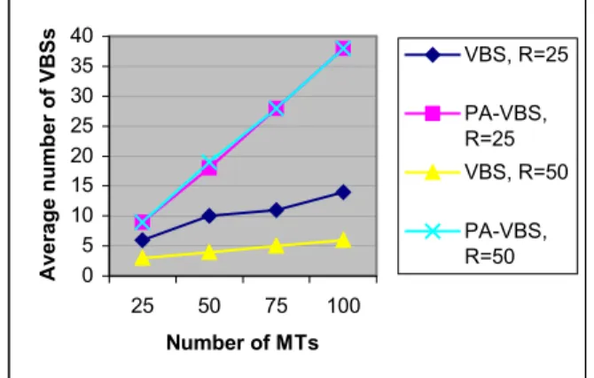
1. Average Number of VBSs - The smaller this number, the more the number of mobile nodes that have to be served by each VBS, and vice versa.
2. Average VBS Duration - The average time duration (in seconds) for which a mobile node remains a VBS. This is a very important performance measure since it is a measure of system stability. This is due to the fact that the larger the duration, the more stable the scheme. Therefore, the sought value for this measure is actually infinity, as in conventional cellular networks where a base station serves as a base station during its lifetime, or the whole lifetime of the cellular network.
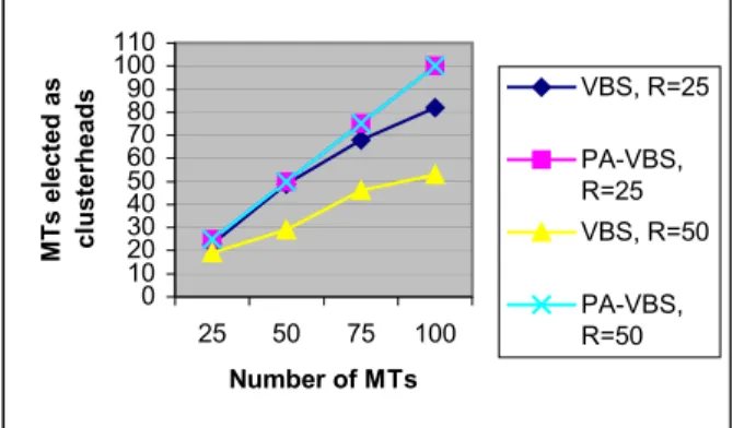
3. Total Number of Mobile Nodes Elected as VBS - The total number of mobile nodes elected as VBSs during the whole simulation run-time. A small value of this statistic reflects the system's tendency to elect the same set of VBSs. This implies that a small fraction of the mobile nodes is elected as VBSs in the case of small values. The results of the corresponding experiments were compared against the VBS infrastructure-formation scheme that was shown in [10] to overcome the drawbacks of the previously proposed infrastructure-creation protocols. VBS was also shown in [10], by means of simulation, to surpass max-min [8] in its overall performance.
4.3. Simulation Results
Observing the simulation results of Figure 7 shows that PA-VBS produces a larger number of clusterheads than VBS. This is actually because PA-VBS distributes the work load amongst a number of nodes that satisfy the power requirements, unlike VBS which tends to elect the same set of nodes with the smallest IDs again and again. The growth in the number of clusterheads is linear with the number of MTs in the case of PA-VBS. Moreover, the number of
clusterheads remains constant when the wireless range is varied. On the other hand, the number of clusterheads in the case of VBS decreases when the wireless transmission range, R, increases. With networks with much larger populations, especially those that have CBR-traffic sources, this will cause considerable MAC delays due to the large number of MTs that are simultaneously contending for medium access at a constant rate.
The average VBS duration, as explained before, is an important measure of the stability of any clusterhead-formation protocol. Figure 8 clearly shows, regardless of the value of THRESHOLD_1 for the MTs running PA-VBS, that since VBS elects nodes based on their ID numbers, they remain as clusterheads for longer periods than in the case of PA-VBS. However, in practice, this cannot be achievable since clusterheads consume more power than other MTs, and their battery power drains quicker. Hence, VBS is more prone to undergo disorder. The results show that the clusterhead duration, on average, is between 1.9 and 3 times more in the case of VBS. This implies that using VBS will drain all the battery power of the clusterheads until they can no longer operate.
0 5 10 15 20 25 30 35 40 25 50 75 100 Number of MTs Averag e n u mb er o f VBSs VBS, R=25 PA-VBS, R=25 VBS, R=50 PA-VBS, R=50
Figure 7: Impact of network density on number of VBSs
Figure 9 shows that PA-VBS achieves load balancing amongst the nodes in the wireless ad hoc network. Every node is elected as a clusterhead at least once during the simulation run-time, regardless of the wireless transmission range. On the contrary, VBS elects a smaller fraction of the total number of mobile nodes as clusterheads during the entire simulation run-time. In addition, the total number of nodes elected as clusterheads decreases as the wireless range increases. This implies that VBS does not guarantee fairness amongst the wireless nodes as with PA-VBS. As a result of increasing the wireless range, there was a
40% drop in the total number of VBSs in the case of 50 nodes, and around 29% with 75 and 100 MTs. This result proves that PA-VBS attains fair clustering.
0 500 1000 1500 2000 2500 3000 3500 4000 25 50 75 100 Number of MTs A ver age VB S dur ation (seconds) VBS PA-VBS, TH1=0.75 PA-VBS, TH1=0.90 0 10 20 30 40 50 60 70 80 90 100 110 25 50 75 100 Number of MTs MT s elected as cl u s terh ead s VBS, R=25 PA-VBS, R=25 VBS, R=50 PA-VBS, R=50
5. Conclusions
In this paper, we introduced a novel infrastructure-creation protocol for wireless mobile ad hoc networks, namely PA-VBS. Likewise, the paper provided an in-depth explanation of the operation of our proposed PA-VBS infrastructure-creation protocol. Also, packet-level simulation experiments of wireless mobile ad-hoc networks, with variable node densities, were conducted, and the results were examined. PA-VBS surpasses PA-VBS [10] in balancing the load amongst the nodes of the wireless mobile ad hoc network. Unlike other clustering protocols, PA-VBS allows the mobile nodes to use their valuable battery power gracefully. On the contrary to VBS, PA-VBS does not drain all the battery power of the clusterheads since it introduces the concept of service denial. Besides, PA-VBS always elects 100% of the wireless
nodes as clusterheads. Hence, it attains fair clustering. All the nodes will serve as a clusterhead, at least once, during their operation.
PA-VBS can be utilized, in future research, as a basis for routing in wireless mobile ad hoc networks. PA-VBS can be used to further guarantee the selection of routes that penetrate low-contention zones, and avoid high-contention ones.
References
[1] S-J. Lee, M. Gerla and C-K. Toh, “A simulation study of table-driven and on-demand routing protocols for mobile ad hoc networks,” IEEE Network, Vol. 13, No. 4, July/August. 1999, pp. 48-54.
[2] Tsu-Wei Chen and Mario Gerla, “Global State Routing: a new routing scheme for ad hoc wireless networks,”
Proceedings of IEEE ICC, 1998.
Figure 8: Impact of network density on clusterhead duration
[3] C. E. Perkins and E. M. Royer, “Ad-hoc on demand distance vector routing,” Proceedings of the 2nd IEEE
Workshop on Mobile Computing Systems and Applications,
Feb 1999, pp. 90-100.
[4] David B. Johnson and David A. Maltz, “Dynamic source routing in ad hoc wireless networks,” Mobile Computing, Kluwer Academic Publishers, 1996, pp. 153-181.
[5] S. R. Das, C. E. Perkins and E. M. Royer, “Performance comparison of two on-demand routing protocols for ad-hoc networks,”IEEE INFOCOM, March 2000.
[6] C. R. Lin and M. Gerla, “A Distributed Architecture for Multimedia in Dynamic Wireless Networks,” Proceedings of IEEE GLOBECOM, New York 1995, pp. 1468-1472. [7] I. Chalmtac and A. Farago, “A new approach to the design and analysis of peer-to-peer mobile networks,” ACM-Baltzer J. Wireless Networks, pp. 149-156, 1999.
Figure 9: Impact of network density on number of mobile nodes elected as clusterheads during the
entire simulation run-time [8] A. D. Amis, R. Prakash, T.H.P. Vuong and D.T. Huynh,
“Max-min d-cluster formation in wireless ad-hoc networks,”
IEEE INFOCOM, March 2000.
[9] C-C Chiang, H-K Wu, W. Liu, and M. Gerla, “Routing in clustered multihop, mobile wireless networks with fading channel,”, Sicon 1997.
[10] H. Hassanein and A. Safwat, “Virtual base stations for wireless mobile ad hoc communications: an infrastructure for the infrastructure-less,” To appear, “The International Journal of Communication Systems”, July 2001.