PAPER • OPEN ACCESS
Pumping wells super flexible closed-loop control technology research
and testing applications
To cite this article: Zhang Shengli et al 2020 J. Phys.: Conf. Ser. 1654 012012
View the article online for updates and enhancements.
Pumping wells super flexible closed-loop control technology
research and testing applications
Zhang Shengli1 Wang Fang1 Yang Song1 Chang Penggang1 Wei Siqi1 Liang
Xinkun2 Song Chen3 Luo Ruichang4
1Engineering Technology Research Institute of Huabei Oilfield Company; 2Department of Engineering Technology, China southern petroleum exploration &
development corporation; 3Bayan Exploration and Development Branch of Huabei
Oilfield Company;4.No.1 Oil Production Plant of Huabei Oilfield Company;
Abstract: In the late period of oilfield development, beam pumping is the most common artificial lifting method. With many problems such as high energy consumption, low efficiency and poor working condition, conventional drive control and production management mode can hardly meet the need of development. In this paper, a method of super flexible closed-loop control for beam pumps is proposed. With coupling analysis of loads, power and position of crank in a pump cycle and calculating, motor speed and corresponding frequency output curve can be obtained. Thus, variable motor speed with very little change on power mode is achieved. Through the driving frequency output and the drive power change, the variation of loads, torque and power of the whole beam pumping system can be reduced. In this way, working condition and efficiency of the pump can be improved and the abrasion of rod string and energy consumption can be reduced, meanwhile, service life of the whole system can be prolonged. After field test, the result of energy saving and efficiency improving can be seen.
1. Overview
The main lifting way of oil production is beam pumper in China. According to the statistics, there are more than 130000 rod pumped wells in Petro china co., LTD, which account for 85% of the total number of production Wells1. For the operating characteristic of beam pumping unit always make
electric motor and reducer casing under periodical alternating load, the amplitude of motor input power curve fluctuation are dragged largely, and there are even overload and reverse power generation; A shortage of well fluid produce phenomenon of the gear of reducer: “back shock”; Imbalance between vibration and inertia load bear from rod string cause the impact on the rod string; Uniform speed operation of the crank is not only unsuitable for ideal speed requirements of plunger in well and cause a big peak acceleration, but also makes conditions of the whole pumping system relatively worse: rod string eccentric wear,decrease of pump efficiency, decrease of security life of the whole pumping system23.
In order to improve the operation condition of lifting system of beam pumping units, we introduce a variety of energy-saving control cabinets, high slip motors and gap pumping equipment in recent years. Although we have achieved some results, such as low installed power of pumping unit, improved pump efficiency and improved system efficiency, increasing frequent fluctuations production of stripped wells in recent years, the existing control technology is difficult to adjust
2
parameter timely and achieve dynamic control. The condition of rod pumped well is difficult to adapt to changing bottom hole flowing, which puts forward a new topic for intelligent dynamic control of rod-pumped well.
Based on the characteristics of beam pumping unit load cyclical changes, we put forward technical approaches of optimization control of pumping unit super flexible operation process——original equipment combination of pumping unit lifting system should be kept, then motor is drag with variable speed and output torque converter, which can improve the ground driving system and force condition of the rod string. According to the down hole feed flow to pump, it can change movement time of up and down stroke and the rate of plunger that increase the effective stroke and improve the pump efficiency. Thus, on the premise of keeping production,
it can reduce system losses and running energy consumption and improve the efficiency life of pumping well system4.
2. The structure and working principle of system
Optimization control technology core of pumping unit super flexible operation process is come true by rod string stress analysis in real time and dynamic frequency conversion control mode that can adjust the motor speed and speed distribution of plunger pumping. It can optimize the operation time of up and down stroke and avoid mechanical impact load of reversal point, which can reduce ground transmission and alternating poles fatigue for automatic parameter adjustment according to feed flow and variable speed operation. Thus the purpose of improving pump efficiency, reducing the
mechanical loss and prolonging pump inspection period can be brought about.
Pumping well super flexible closed-loop control system is composed of single well control cabinet and control strategy. The single well control cabinet includes inverter, RTU, load sensor, electric parameter sensor, crank angle position sensor, wellhead liquid quantity sensor. Acquisition parameters are composed of stroke, times of stroke, the ground indicator diagram, current, voltage, active power, reactive power, current peak balance, power peak balance, motor frequency, etc.
Control strategy is a set of algorithm that includes analysis of load and power of rotary rod pumped well and suspension center speed and acceleration, and the optimization calculation. Control strategy is not only composed of kinematics model and dynamics model of pumping unit motion with variable velocity, but also three dimensional coupling mathematical model of pumping rod, oil tube and fluid. The target is minimum energy consumption, at the same time, constraints are that roof bolt stress and static torque remain stationary. We will draw the best velocity curve of crank axle, and confirm optimization method of electrical machinery variable speed curve. Finally control strategy of pumping wells flexible operation will be achieved.
2.1 Basic principle and control method of super flexible operation 2.1.1 Initiative super flexible operation control method
According to relationship between suspension center movement velocity at different location and suspension center load, initiative super flexible operation control can make an operation plan of suspension center load and the change of electric motor rotation speed. The technology is showed by initiative variable speed drive. When suspension center load
decline, electric motor driving velocity will increase and keep certain driving force export, that can make mechanical system store energy; When suspension center load increase, electric motor driving force export is repressed initiatively by driving force released by mechanical system in process of deceleration and need by kinetic energy compensatory system. Based on the control of measurement and rate of driving force, kinetic energy stored of mechanical system can be used sufficiently. We can export continuous smooth torque with no jump. Finally torque balance converter of reducer casing take-off spool achieve crest reduced and trough increased.
2.1.2 Control method adjust by itself of super flexible operation
The main factor of keeping the product stable is stabilizing producing pressure drop of rod pumped well. By means of closed-loop control parameter set, system makes times of stroke adjust by itself at certain circumscription, which can adapt to fluctuation of feed flow under the shaft. Gear shift adjustment at single cycle get pump max coefficient of admission, that gains desired flow rate at the lowest times of stroke. Through advisable submergence depth set for closed-loop control parameter, the time ratio of up and down stroke revises between 0.5 and 2 by itself which is not only suitable for middle and high capacity well, but also for deficient feed flow well, that can improve suffusion level and avoid fluid heating.
Fig.1 Auto adapted closed-loop control flow chart 2.1.3 Follower power driven method
Follower power driven method is achieved by re distribution of pumping unit load power technology and rated power driven by dynamic change technology:
When the speed is rated at 50Hz, the output voltage of the converter is rated voltage. If the output frequency increases to 40Hz, the maximum output voltage of the converter is kept constant, and the rated output power is constant, which is what we call constant power regulation. At this point, the torque decrease with the increase of the speed, and the size of the motor load need to be adjusted to prevent insufficient motor output torque5. Therefore, by measuring motor's working ability at the
maximum voltage (UCP) and the maximum frequency (FCP) to modify the voltage / frequency curve, you can achieve super flexible control. Through the motor output shaft speed, acceleration, active super flexible operation control technology can change the output power of the motor. Enhance the load at original super low load rate period and reduce the load at original overload period, that is the principle of re distribution of the speed. That is why the motor maintains a certain range of load rate in the whole cycle.
4
3. Basic algorithm of super flexible control
3.1 The principle of super flexible operation control
Through the establishment of kinematics and dynamics model of pumping unit at variable speed and machine – bar coupled model, we consider that inertial load affect on dynamic characteristic of pumping unit and variation of vibration and inertial load in suspension point load, and optimal rate curves of suspension point can be obtained. Optimal speed curve calculated of crank is optimized in order to establish super flexible optimization operation control strategy to achieve super flexible control.
3.2 Dynamics model coupled of motor-rod-pump system driven by super flexible operation with variable speed
We make the target motor-rod-pump system which swab gas-oil mixture with variable speed. According to the effect of inertial load of every moving part driven by driving gear, rod-liquid- pipe characteristics coupled, and piston pumps pumping the mixture of oil and gas, we establish fluid solid coupled dynamics model that is between two-phase flow and pumping pump valve motion, through the kinematics model of pumping unit and rod - liquid - tube coupled dynamic model, and determine boundary condition6s.
3.2.1 The kinematics and dynamics model of the super flexible operation of the beam pumping unit The kinematic and dynamic models of the beam pumping unit with constant speed are analyzed, and the mathematical model of the four link mechanism is established by the complex variable vector method. Considering the influence of the inertia load, the torque balance equation of the crank shaft is established. The angular velocity of the crank is known, and the velocity curve is processed by three spline interpolation and micro business law。The variable angular acceleration of the crank shaft is obtained. Inertia torque with variable speed is solved.
The kinematics and dynamics model of beam pumping unit variable speed operation: 𝜌𝑟𝐴𝑟 𝜕𝑣𝑟 𝜕𝑡 = 𝜕𝑓𝑟 𝜕𝑥 − 𝜌𝑟𝐴𝑟 𝑑2𝑢 𝑑𝑡2− 𝜌𝑟𝐴𝑟𝑣𝑟𝑟( 𝑑𝑢 𝑑𝑡+ 𝑣𝑟) + 𝜌𝑟𝐴𝑟𝑣𝑟𝑓𝑣𝑓 (1) 𝜕𝑓𝑟 𝜕𝑡 = 𝐸𝑟𝐴𝑟 𝜕𝑣𝑟 𝜕𝑥 (2) 𝜕𝑣𝑓 𝜕𝑡 + 𝑣𝑓 𝜕𝑣𝑓 𝜕𝑥 + 1 𝜌𝑓 𝜕𝑃𝑓 𝜕𝑥 = 𝑔 − 𝜌𝑟𝐴𝑟𝑣𝑟𝑓+𝜌𝑡𝐴𝑡𝑣𝑡𝑓 𝜌𝑓(𝐴𝑡𝑖−𝐴𝑟) 𝑣𝑓+ 𝜌𝑟𝐴𝑟𝑣𝑟𝑟 𝜌𝑓(𝐴𝑡𝑖−𝐴𝑟)( 𝑑𝑢 𝑑𝑡+ 𝑣𝑟) (3) 𝜕𝜌𝑓 𝜕𝑡 + 𝜌𝑓 𝜕𝜌𝑓 𝜕𝑃𝑓 𝜕𝑣𝑓 𝜕𝑥 + 𝑣𝑓 𝜕𝑝𝑓 𝜕𝑥 = 0 (4)
3.2.2 Simultaneous solution of kinematic and dynamic behavior coupled of machine and rod
Rod liquid pipe three-dimensional coupled wave equations are established. upper boundary is variable suspension speed operation curve, and lower boundary is pump dynamometer card. 3D wave equation of rod - liquid- pipe is solved used by implicit difference scheme when the initial condition is the dead operating parameters. Through strong relationship coupled of light bar and rod-liquid-pipe-pump, dynamic and kinematic characteristic of transmission mechanism and rod liquid pipe pump system can be mutual boundary. All characteristics of super flexible pumping oil system can be obtain by simultaneous solution.
Kinematic and dynamic model coupled of machine and rod: { 𝑑ℎ𝑠 𝑑𝑡 = 1 𝑓𝑣𝑠[−𝐴𝑝 𝑑𝑢𝑝 𝑑𝑡 − 𝜇𝐿𝑥𝑠ℎ𝑠√ 2𝑚𝑠𝑔 𝜌𝑓𝑣𝑠] ℎ𝑠|𝑡 = 𝑡𝑜𝑠= 0 (5) 6
{ 𝑑ℎ𝑑 𝑑𝑡 = 1 𝑓𝑣𝑑(𝐴𝑝 𝑑𝑢𝑝 𝑑𝑡 – 𝜇𝐿𝑥𝑑ℎ𝑑√ 2𝑚𝑑𝑔 𝜌𝑓𝑣𝑑) ℎ𝑑|𝑡=𝑡𝑜𝑡= 0 (6)
3.2.3 Variable speed operation optimization method and saving energy principle of machine rod pump system
1) Super flexible control operation can reduce start and running current and power of motor;
2) Sudden load mutation of motor and gearbox is removed, and the damage of the back shock is decreased. Large suspension point load during the down stroke and fast downward speed of rod leading to generating electricity by passive motor dragged can be avoided by super flexible drive.
3) Super flexible variable speed operation can make continuous and smooth torque output driven by motor, and reduced peak torque greatly, that play the role of "clipping peak and filling valley". 4. Field application effect analysis
4.1 Pumping wells super flexible closed-loop control conditions
Super flexible closed-loop control strategy is suitable for walking beam pumping unit lifting system(asynchronous motor, permanent magnet synchronous motor, high slip motor).When the motor operating characteristics is hard characteristic, application effect is more significant. The technique is very applicable to conventional thin oil wells and can achieve variable speed control of walking beam pumping unit lifting system. It has no special requirement for feed flow. Driving mode does not apply for thick oil wells, because down resistance is too large to cause system shutdown. There is no experiment for tower type pumping unit(vertical type) driven by linear motor in advance.
4.2 Saving energy effect of super flexible optimization operation control 4.2.1 Saving energy effect comparison
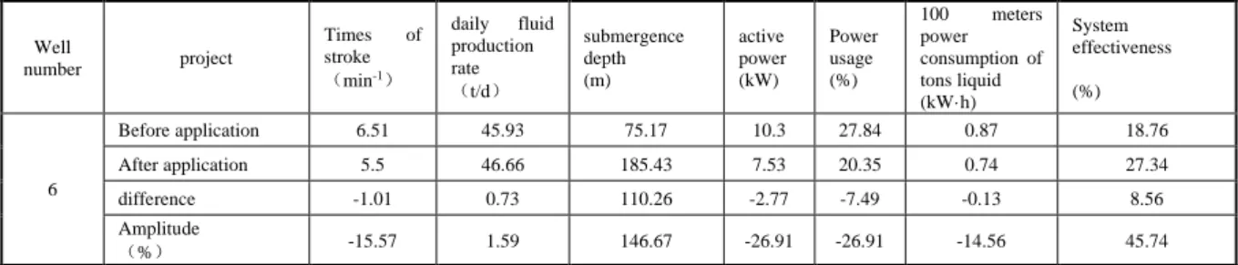
Super flexible operation control is applied on 6 wells of oil production plant 1 in certain Oilfield. Comparison results show that application of the technology make liquid producing capacity stable at times of stroke of 1.01min-1(15.57% declined) and sunk degree rise by 110.26 meters. At the same
time, active power fall by 2.77kW(active brownout--26.91%). The equivalent power decreases 3.28kw (comprehensive energy saving rate--28.82%). 100 meters power consumption of tons liquid fall by 0.13 kWh(decrease extent--14.58%t). System efficiency increase 8.58% (increase amplitude of 45.74%). specific data can be saw in table 1.
Table 1 Before and after application contrast of six wells
Well number project Times of stroke (min-1) daily fluid production rate (t/d) submergence depth (m) active power (kW) Power usage (%) 100 meters power consumption of tons liquid (kW·h) System effectiveness (%) 6 Before application 6.51 45.93 75.17 10.3 27.84 0.87 18.76 After application 5.5 46.66 185.43 7.53 20.35 0.74 27.34 difference -1.01 0.73 110.26 -2.77 -7.49 -0.13 8.56 Amplitude (%) -15.57 1.59 146.67 -26.91 -26.91 -14.56 45.74
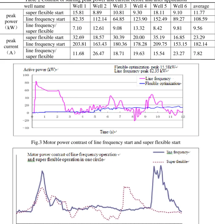
4.2.2 Contrast and analysis of starting power and current
In order to further compare starting capability of super flexible technology, the starting current and starting power of 6 wells were compared. The results showed that both the starting power and the starting current decreased obviously(saw in table 2). From the comparison of the test data, peakedness ratio of starting power of 6 wells is 9.6:1, and the peakedness ratio of starting current is 7.8:1.
6
Table 2 Contrast of starting peak power and current before and after application
well name Well 1 Well 2 Well 3 Well 4 Well 5 Well 6 average
peak power (kW)
super flexible start 15.81 8.89 10.81 9.30 18.11 9.10 11.77 line frequency start 82.35 112.14 64.85 123.90 152.49 89.27 108.59 line frequency/
super flexible 7.10 12.61 9.08 13.32 8.42 9.81 9.56
peak current (A)
super flexible start 32.69 18.57 30.39 20.00 35.19 16.85 23.29 line frequency start 203.81 163.43 180.36 178.28 209.75 153.15 182.14 line frequency/
super flexible 11.68 26.47 18.71 19.63 15.54 23.27 7.82
Fig.3 Motor power contrast of line frequency start and super flexible start
Fig.4 Motor power contrast of line frequency operation and super flexible operation 4.2.3 Contrast and analysis of indicator diagram
Comparative data of line frequency and super flexible operation show that times of stroke rush down and liquid production keep stable after the use of super flexible drag device. At the same time, submergence depth rise to alleviate the lack of fluid effectively. In order to further illustrate this problem, some wells of indicator diagrams were compared. Indicator diagram contrast with XX well as an example is shown in Figure 5.
Fig.5 Indicator diagram contrast of line frequency operation and super flexible operation 5. Conclusions and recommendations
1) The technique is able to track the load changes, and timely adjust motor revolution and power in the operation process, which play the role of "clipping peak and filling valley" . The peak power decreases 2.26 times compared with power frequency operation. The peak current decreases 2.95 times and curve is smooth.
2) The technique is applied on six wells. When times of stroke falls by 1.01min-1(15.57% dropped),
liquid production increases 0.73t/d (1.59% increased); submergence depth increases significantly. Active power falls by 2.77kW (active power saving-- 26.91%).The conversion of the equivalent power decreases 3.28 kW (comprehensive energy saving rate -- 28.82%). Tons liquid power consumption between 100 meters falls by 0.13 kWh(decreased width--14.58%).The efficiency of the system increases 8.58 %( increased width--45.74%).
3) Due to the technical method implementation of frequency adjustment with the load, up and down stroke work time reverse compared with power frequency operation. Accelerated motion at the initial stage of stroke improve fully charged and reduce the traveling valve leakage.
References
[1] Zhang Zhixue. Application of SRD to Energy Saving Long Stroke Pumping Unit [J]. Petroleum field Equipment, 2009, 38 (8): 75-78.
[2] Luan Qingde, Yan Yukui, Zhao Jifeng, et al. Power Consumption Analysis and Measures for Power Saving Pumping Unit [J]. Petroleum field Equipment, 2008, 37 (10): 11-14.
[3] Xiao Yuan, Zha Hong Min, Chen Yingang, etc. Pumping unit energy-saving controller based on the technology of frequency conversion model[J]. Petroleum machinery, 2005, 33 (8): 42-44. [4] Li Hongcai, Qin Defu, fish Gang, et al. Study of Energy-saving Type Ultra-low Frequency Stroke
Pumping Unit [J]. Petroleum field Equipment, 2010, 39 (5): 49-51.
[5] Ke Wei, Li Cailiang, Wang Qiyan, et al. Concept of Coaxial Secondary Counterbalanced Beam Pumping Unit and Energy-Saving Analysis [J]. Oil field Equipment, 2009, 38 (4): 7-10. [6] Zhou Feng, Cao Hui. Study on Motor Selection for New Linear-submersible Oil Pumping[J].
Petroleum field Equipment, 2008, 37 (3): 14-19.
[7] Hu Songhua, white Cunan. Research and Application of Flexible Drag Control for Pumping Unit[J]. Petroleum Geology and Oilfield Development in Daqing, 2006, 25: 73-74.
8
Conversion of Pumping Unit and Result Interpretation of Production Increasing and Energy Saving[J]. Petroleum Geology and Oilfield Development in Daqing, 2005, 24: 61-63