6
I
January 2018
Modeling and Operation of a Micro Grid using
Fuzzy based Incremental Conductance for a PV
System
Dr.V.S.Vakula1, Mrs V.V. VijethaInti2, Ms. T. Geethanjali3 1
Assistant Professor & HOD, Department of EEE, UCEV, JNTUK, Vizianagaram, Andhra Pradesh, India, Research Scholar, Department of EEE, JNTU Kakinada, Andhra Pradesh, India
3
PG Student, Department of EEE, UCEV, JNTUK, Vizianagaram, Andhra Pradesh, India
Abstract: This article presents the application of renewable energy sources like wind and solar energy for modeling and operation of a micro grid. A current-source-interface multiple-input dc-dc converter is used to combine the wind and solar energy to the main dc bus. In this article, PMSG is used with a variable speed control method whose approach is to capture the maximum wind energy below the rated wind speed. This analysis provides the variations in load power with the change in solar irradiance wind energy. Fuzzy-based incremental conductance has been implemented for solar PV system. As a case study a 30-KW wind/solar hybrid power system model is examined. The observed dynamics demonstrates that the anticipated power system is a possible option for a sustainable micro grid application.
Keywords: Photovoltaic system, MI Cuk converter, MPPT, Incremental conductance, Fuzzy logic controller
I. INTRODUCTION
The importance of renewable energy sources is increasing now a days as its exhaustive nature also the demand for electricity is high and cost of fossil fuel is raised [1]. Solar energy is a inexhaustible renewable source of energy which is available in free of cost. It is also used in various applications [2].Alone, wind energy is capable of supplying large amounts of power but it is not continuously available for conversion into electricity. By utilizing solar energy, the power generation depends on the amount of sunlight. Solar energy varies all through the day and throughout the seasons and is embellished by dust, fog, cloud cover, etc. These energy sources are most significant because these are environmental-friendly.
The intermittent properties of wind and photovoltaic systems make the power system unreliable. Using a single common current source interface multi-input dc-dc converter [3] with dc bus system is used because it provides the interchangeable inputs and combined the advantages of various renewable energy sources. The anticipated micro grid is prepared with energy storage devices such as batteries [4]. Fuzzy-based incremental conductance MPPT is proposed in this article. An MPPT tracks the maximum power point (MPP) based on the I-V characteristic curve of the PV module with maximum output power. Maximum power varies with solar irradiation and solar cell temperature [5]. To make the most excellent use of PV panels, it is necessary to operate always at the MPP. The function of the MPPT technique is to control the PV system and operate as close to its optimal peak power point.
II. MODELING OF SYSTEM
A. Solar System
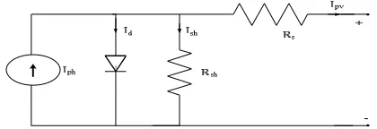
[image:2.612.200.410.647.719.2]A photovoltaic (PV) structure directly converts sunlight into electricity. PV cell is the basic device of a PV structure. A Cell may be grounded to form panels. The output terminals of a PV structure ie., solar cell output current and voltage a can be directly coupled to small dc loads such as fans, water pumping, and DC motors. The PV module output characteristics depend on the cell temperature, solar irradiation. The figure1 shows the equivalent circuit of a PV array.
Aphotovoltaic cell is modeled by a photocurrent source, parallel diode, shunt resistance (Rsh) and series resistance (Rs) [6].A single solar PV cell can produce a small amount of power. Solar cells are connected in series or parallel to increase the output power of the system,
= ℎ- −1 (1)
Where
I0 is the PV array output current
v is the PV output voltage
Iph is the cell photocurrent
Irs is the reverse saturation current
k0 is a constant,
ns number of PV cells connected in series,
np number of strings connected in parallel.
The cell photocurrent is calculated from
ℎ=[ + ( − )] (2) where
Iscr cell short-circuit current
kishort-circuit current
Trcell reference temperature
S solar irradiation in mw/cm2
Moreover, the reverse saturation current of a PV cell is computed from
= exp − (3)
where Trcell reference temperature
Irrreverse saturation at Tr
EG band-gap energy of the semiconductor
B. Wind Turbine Modeling
The wind turbine (WT) converts wind energy to mechanical energy by applying torque to a drive train. WT is necessary to estimate the torque and power production and the effect of wind speed [7]. The torque and power produced by the WT is within the
interval[Vmin,Vmax],where
Vmin is minimum wind speed
Vmaxis maximum wind speed
= ( , ) (4)
Where
CP is known as the power coefficient which characterizes the ability of the WT to extract energy fromwind
Cq is the torque coefficient
= (5)
= ∗ (6)
= (7)
Where
Cp=Coefficient of performance,
Pm=Mechanical output power (watt),
=blade pitch angle =Air density (kg/m3),
Vwind=wind speed (m/s)
A=Turbine swept area ,
=Tip speed ratio
T=Torque of wind turbine,
=Angular frequency of rotational turbine (rad/sec).
The performance coefficient Cp ( , ), depends on tip speed ratio and blade pitch angle , determines the kinetic energy of
wind that can be captured by the wind turbine system. A nonlinear model describes Cp ( , ) as
( , )= − + + (8)
C. MI Cuk DC-DC
A multiple-input (MI) converter permits the combination of different renewable energy sources in a single converter[8]. These energy sources have the capability of diversifying different energy sources and increasing the reliability of the system. These MI converters supply continuous input current through the inductors, and therefore no discontinuous mode is possible and also provides flexible operation. An MI Cuk converter uses capacitor as a storage device. The MI cuk converter has an output voltage which is either greater than or less than the input voltage. In steady state, the current through the inductors remains constant. For satisfying the steady state requirements the average voltage value of the inductor over a commutation period have to be zero .
. Fig 2. MI Cuk converter
Switching state 1 (0<t<d1Ts): At t=0,in this mode switches Q1 and Q2 are turned ON and inductor L1 and L2 are charged with
voltages across Vin1 and Vin2, respectively.
Switching state 2 (d1 Ts<t< d2Ts): At t-d1T, in this mode switch Q1 is turned OFF while switch Q2 is still ON (according to the
assumption d1<d2). Therefore, inductor L1 is discharged with a voltage across Vin1 – V0 into the output load and the capacitor
through the diode D1, while inductor L2 is being charged by a voltage across V2.
Switching state 3 (d2Ts<t<Ts): At t=d2T, In this mode only the diode D conducts and all the switches are turned off .
III. PROPOSED ALGORITHM
Maximum power point tracking technique is used to develop the effectiveness of the solar panel [9]. There are many algorithms that are able to track MPPs. The I-V curve of the solar PV can be varied considerably with atmospheric conditions such as irradiance and temperature [10].The MPPT algorithm used in this paper is Fuzzy-based Incremental conductance (INC) method. MPPT devices are normally included into an electric power converter system which affords voltage and current conversion. The best possible performance of the PV system mainly depends on the power converter.
The proposed tracker combines two algorithms: INC algorithm and Fuzzy Logic (FL) controller.
The aim of the proposed method is to decrease the fluctuations occurring around MPP. Another attainment of the proposed hybrid controller can be able to improve the steady-state performance as well.
A. Incremental Conductance
Incremental conductance (INC) is one of several MPPT methods which employ both PV voltage and current. This MPPT method has an improved performance especially under variable climatic conditions [11]. INC offers more advantages than perturb and observe method (P&O) [12].
This algorithm uses the direct conductance of the PV unit is I/V and the incremental conductance is dI/dV and compares them in order to obtain the MPP.
∆
∆ = at the MPP (9)
∆
∆ >− Left of MPP (10)
∆
This algorithm is based on the slope of the P-V curve is equal to zero at MPP dP/dV=0 since,
= + (12)
= + (13)
+ = 0 (14)
Fig. 3. Flowchart of an incremental conductance method
However, condition in (14) is difficult to obtain and therefore, there is a small permitted error. Equation (14) can be rewritten as
+ = (15)
B. Fuzzy Logic Controller
A Fuzzy logic controller is a mathematical tool for dealing with uncertainty. Fuzzy Logic Controller (FLC) is one branch of the intelligent control in which the concept of FLC is achieved by mimicking and adopting the behavior of human being [13]. FLC comprises fuzzification process, inference system, rule, and defuzzification.
1) Fuzzification: It converts crisp inputs into fuzzy inputs. The values of membership function are allocated to the linguistic variables using three fuzzy subsets called upper negative (UN), upper zero (uz), upper positive (up). The input variable of fuzzy logic (FL) control includes (E), change of error (CE) and double change in error (DE).These variables are processed through inference system and through some rules. These conditions are done to generate the output of FL.
2) Inference engine: Fuzzy inference systems mainly associated with fuzzy rule base and fuzzy implication. The fuzzified inputs are fed to the deduction engine and the rule base is then applied. By fuzzy implication method output fuzzy sets are identified. The commonly used fuzzy implication method is Min-Max. The consequent fuzzy region is restricted to the minimum (min) of the predicate truth while selecting output fuzzy set. The fuzzy output region is updated by taking the maximum (max) of these minimized. Fuzzy sets during shaping of output fuzzy space.
3) Defuzzification: Defuzzification is a method where fuzzy sets values are altered into crisp values. Here, the output of fuzzy is a change in duty cycle (dD). The method chosen here is a center of gravity as it is simple and fast for calculation. The formula for center of gravity method is given in equation.
=∑ ( )
∑ ( ) (16)
F Fig. 4. Proposed Algorithm
C. Proposed Algorithm
The proposed hybrid algorithm between INC algorithm [14] and fuzzy logic control algorithm [15] is described in fig.4. As already stated the output of INC algorithm is (E) applied to fuzzy logic control (FLC). The error, coming from Incremental algorithm is processed to obtain change error (CE), and double change in error (DE) which can be obtained as follows
= + (17)
= ( )− ( −1) (18) = ( )− ( −1) (19)
Here error (E) is taken such that describes incremental conductance condition to zero where MPP is reached in equation (17). E (k)
and E (k-1) is the present and the past error values respectively, whose difference gives us the change of error in equation (18).
IV. RESULTS AND DISCUSSION
[image:6.612.201.415.430.557.2]The proposed method employs the INC and the FL based INC controller to adjust a duty cycle of Cuk converter to achieve MPP condition. Once the MPP is reached, the MIC controller controls the output voltage of by adjusting the MIC’s duty ratios. The complete flow chart of INC control method is as shown in fig.3,where a tolerance which equals zero is used for this condition in the simulation because this tolerance value allows PV modules to remain at their MPP, thus producing steady state error at the operating points of the PV system.
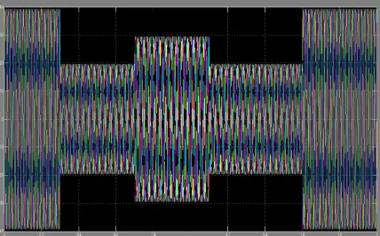
Fig. 5. Output voltage waveforms of the inverter
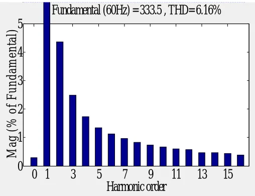
[image:6.612.201.415.589.722.2]Fig. 7. THD analysis of the output voltage of grid-connected hybrid system
Fig. 8. THD analysis of output voltage of grid-connected hybrid system using fuzzy-based incremental conductance
A simulation model is created using Matlab/Simulink to authenticate the performance of the anticipated method for MPPT in a photovoltaic system under variable climate condition. The output waveforms of grid-connected wind/PV system simulation results are shown in fig.5 and fig.6. Total harmonic distortion of the output voltage of the grid-connected hybrid system is given in fig.7 from the FFT analysis it is clear that the THD is 6.16%.
Fuzzy-based Incremental controlled MPPT approach is used for PV output voltage which can be used to track maximum power
point of PV array smoothly. Grid-connected PV/wind systems are modeled and simulated. Using the fuzzy-based Incremental control strategy the PV system generates a sinusoidal voltage which has the THD value of 0.40%. In order to evaluate the proposed system, the results are can be evaluated using conventional INC. It is clearly described that the conventional INC alone is not able to decrease fluctuation occurring around MPP.
V. CONCLUSION
In this paper, a hybrid of incremental conductance algorithm and fuzzy logic controller is employed to achieve MPPT of photovoltaic systems. The anticipated MPPT method is simulated in Matlab/Simulink. Based on comparison of the THD values between conventional incremental method and Propossed algorithm, the performance of the proposed system has improved results. In addition, there is more stability around MPP when the hybrid algorithm is incorporated with a dc-dc converter.
REFERENCES
[1] Litos Strategic Communication, “TheSmart grid: An introduction 2008, pp.1-43, prepared for the U.S. Department of Energy
[2] C.Yaow-Ming, L. Yuan-Chung-sheng, “Multi-input inverter for grid-connected hybrid PV/Wind power system,” IEEE Trans. Power Electron., vol. 22, no. 3, pp. 1070-1077, May 2007.
0 0.2 0.4 0.6 0.8 1 1.2 1.4 1.6 1.8 2
-200 0 200
Time (s)
0 1
3
5
7
9
11
13
15
0
1
2
3
4
5
Harmonic order
Fundamental (60Hz) = 333.5 , THD= 6.16%
M
a
g
(
%
o
f
F
u
n
d
a
m
e
n
ta
l)
0 0.2 0.4 0.6 0.8 1 1.2 1.4 1.6 1.8
-200 0 200
Selected signal: 120 cycles. FFT window (in red): 1 cycles
Time (s)
0 1 3 5 7 9 11 13 15
0 1 2 3 4 5 Harmonic order
Fundamental (60Hz) = 339.3 , THD= 0.40%
[3] B. G. Dobbs and P. L. Chapman, “ A multiple-input DC-DC converter topology,” IEEE Power Electron., Lett., vol. 1, no. 1, pp. 6-9, Mar.2003. [4] E. Muljadi and J. T. Bialasiewicz, “Hybrid power system with controlled energy storage,” in Proc. IEEE 29th IECON, 2003, vol. 2, pp. 1296-1301
[5] K.H. Hussein, I. Muta, T. Hoshino, and M. Osakada, “Maximum Photovoltaic power tracking: an algorithm for rapidly changing atmospheric conditions,” Proc. IEE Generation, Transmission,Distribution, vol. 1442, no.1, pp. 59-64, Jan. 1995.
[6] M. G. Villalva, J.R. Gazoli, and E. R. Filho, “Comprehensive approach to modeling and simulation of photovoltaic arrays,” IEEE Trans. Power Electron., vol. 24, no.5, pp. 1198-1208, May 2009
[7] A. Murdoch, J.R Winkelman, S.H. Javid, and R.S. Barton, “Control design and performance analysis of a 6 MW wind turbine-generator,” IEEE Trans. Power Appl. Syst., vol. PAS-102, no. 5, pp. 1340-1347, May 1983.
[8] S. Bae and A. Kwasinski, “Maximum power point tracker for a multiple-input Cuk dc-dc converter,” Proc. IEEE 31st INTELEC, vol. 20, no. 2, pp. 398-405,
Jun. 2005.
[9] R. Faranda, S. Leva, and V. Maugeri, MPPT Techniques for PV systems: Energetic and Cost Comparison. Milano, Italy: Elect. Eng. Dept. Politecnicodi Milano, 2008, pp.1-6.
[10] D. Sera, T. Kerekes, R. Teodorescu, and F. Blabjerg, improved MPPT algorithms for Rapidly Changing Environment Conditions, Aalborg, Denmark: Aalborg Univ. /Inst. Energy Techol., 2006
[11] B. Liu, S. Duan, F. Liu, and P. Xu, -Analysis and improvement of maximum power point tracking algorithm based on incremental conductance method for a photovoltaic array, in Proc., IEEE PEDS, 2007, pp. 637-641
[12] T. Esram and P. L. Chapman, “Comparison of photovoltaic array maximum power point tracking techniques,” IEEE Trans. Energy Convers., vol.22, no. 2, pp. 439-449, Jun 2007.
[13] Yan S., Yuan J., Leixu: Fuzzy logic control of MPPT for a Photovoltaic power system. In: 9th International Conference on Fuzzy systems and knowledge
discovery (FSKD 2012).
[14] : Research and Applications; November 2003. p. 47-62.