6
I
January 2018
Fuzzy ANFIS Based Optimal Maximum Power
Point Tracking with Estimation of Climatic
Parameter
C Hari Prasad1, B Rajasekhar Reddy2, MCV Suresh3 1, 2
Department of EEE, S V University, Tirupati 3
Department of EEE, SV college of Engineering, Tirupati
Abstract: In recent years, grid connected photovoltic system has emerged with its simplicity, and reliability. A grid connected photovoltaic (PV) system with an efficient Maximum Power Point Tracking Algorithm (MPPT) technique named Adaptive Neuro Fuzzy Inference System (ANFIS) is presented. It computes the instantaneous conductance that is done using the array current and voltage. The second one is junction array conductance, which is estimated using ANFIS cell model. A proposed ANFIS control as an analytical model with a denoising based wavelet algorithm to estimate climatic parameters. The main aim of proposed system is to reach the Grid Voltage demand, manage the power flow, inject the excess power into the grid, and charge the battery from the grid when required. The MPPT method aides will trim down the hardware arrangement increases the efficiency of array power and MPPT response time. The simulation results are provided to validate the proposed ANFIS - PV based MPPT scheme capabilities and to justify the MPPT algorithm operation and estimation capabilities of climatic parameters. Simulation results obtained using MATLAB/Simulink shows the performance of PV system with ANFIS under various modes of operation for power flow management.
Keywords: ANFIS, PV System, Grid, MPPT
I. INTRODUCTION
It's certainly clear that fossil fuels are damaging the climate and that the status quo is unsustainable. There is now a broad scientific consensus that the world needs to reduce greenhouse gas emissions more than 25 percent by 2020 and more than 80 percent by 2050. The idea of harnessing the sun’s power has been around for ages. The basic process is simple. Solar collectors concentrate the sunlight that falls on them and convert it to energy. Solar power is a feasible way to supplement power in cities. In rural areas, where the cost of running power lines increases. Solar power, a clean renewable resource with zero emission, has got tremendous potential of energy which can be harnessed using a variety of devices. With recent developments, solar energy systems are easily available for industrial and domestic use with the added advantage of minimum maintenance. Solar energy could be made financially viable with government tax incentives and rebates. An exclusive solar generation system of capacity 250KWh per month would cost around Rs. 20 lakhs, according to pricing and taxes in 2013. A state-wise analysis reveals that the installed capacities in case of wind and biomass respond strongly to the power tariff for industries while the relationship with the benchmark tariffs is weak though positive. Most of the developed countries are switching over to solar energy as one of the prime renewable energy source. Many methods to track Maximum Power Point (MPP) for PV arrays have been discussed by Trishan Esram and Patrick L. Chapman [1]. It comprises of all the techniques implied in this field. It was shown that at least 19 distinct methods have been already introduced.
Development of a microcontroller based, photovoltaic maximum power point tracking control system was proposed by E. Koutroulis and K. Kalaitzakis [2] in which Maximum power point tracking (MPPT) is used in photovoltaic (PV) systems to maximize the photovoltaic array output power, irrespective of the temperature and irradiation conditions and of the load electrical characteristics. A new MPPT system has been developed, consisting of a Buck-type dc/dc converter, which is controlled by a microcontroller-based unit. The proposed system has high-efficiency, lower-cost and can be easily modified to handle more energy sources.
Adaptive Fuzzy and Neuro-Fuzzy Inference Controller based MPPT for PV systems was explained by M. Balaji Naik, Dr. P. Sujatha[4] to optimize the performance of photovoltaic techniques. This methodology comprises of a hybrid system of fuzzy logic and neural networks. The performance of advanced technique had been presented in this paper. Modeling of solar PV module and maximum power point tracking using ANFIS was proposed by Ravinder Kumar Kharba, S.L. Shimi [5]an adaptive neuro-fuzzy inference system based maximum power point tracking controller has been proposed for a solar PV module. The operation of ANFIS based MPPT controller is investigated under varying weather conditions. After a proper training of presented ANFIS model, the ANFIS based MPPT controller has successfully tracked the maximum available power at different weather conditions.
A.M. Zaki, S.I. Amer explains about Maximum Power Point Tracking for PV system using advanced neural networks technique[6].The cost of electricity from the solar array system is more expensive than the electricity from the utility grid. So, it is necessary to operate the PV system at maximum efficiency by tracking maximum power point at any environmental condition. A three phase inverter for a standalone distributed generation system: adaptive voltage control design and stability analysis has been proposed by Jin-Woo Jung, Nga Thi-Thuy Vu[7].This paper proposes a robust adaptive voltage control of three phase voltage source inverter for a distributed generation system in a standalone operation, which guarantees excellent voltage regulation performance.
Quoc-Nam Trinch, Hong-Hee Lee explains about an Enhanced Grid Current Compensator for Grid-Connected Distributed Generation Under Nonlinear Loads and Grid Voltage Distortions[8], which introduces an advanced current control strategy for grid connected operations of distributed generation, which supports the DG to transfer a sinusoidal current into the utility grid. The performance analysis of photovoltaic modules in non-ideal conditions and the topologies to minimize the degradation of performance caused by these conditions was introduced by Weidong Xiao[9]. It was found that the peak power point of a module was significantly decreased due to only the slightest shading of the module, and that this effect was propagated through other non-shaded modules connected in series with the non-shaded one. Based on this result, two topologies for parallel module connections have been outlined.
A system with an alternative source of energy supply from photovoltaic energy system which operates in case of utility power failure has been discussed by C. Thulasiyammal [10]. The proposed PV system is composed of conventional novel single axis tracking system and PV system with DC-DC boost converter and PWM voltage source inverter. The PV panel voltage is taken as input parameter to maximize the output power.
A unified control strategy for three phase inverter in distributed generation was presented by Zeng Liu[11] in which the inverter is regulated as a current source and the voltage controller if automatically activated to regulate the load voltage. Yun-Pam Lee focused on a DC to AC Inverter; power switching system; ability to generate the drive voltage and switching the power supply between the city electrical system and the solar power system [12]. The main aim is to construct a stabled, completed and low cost of solar energy conversion systems. The latest development of inverters for photovoltaic AC-modules [13] is focused by Soeren Bae, khoej Kjaer . The past technology was based on Centralized Inverters, present on String Inverters and future on Modules and AC-Cells.
The control strategies in photovoltaic charge control including Maximum Power Point Trackers were presented by V. Salas [14]. It has been integrated on a Photovoltaic stand-alone system and has been simulated. A single stage, three-phase three-level neutral point clamped inverter was designed by S. Ozdemir [15]. The proposed voltage source was operated in current controlled mode and a PI current controller was used for the production of switching pattern. Phase Locked Loop method was used to operate proposed inverter parallel with grid.
II. MODELING AND MPPT ALGORITHMS OF PV
The schematic diagram of the three phase grid connected PV system is shown by Fig 1.The system is equipped with a DC link capacitor C, a three phase inverter, an inductor filter L, a PV array that is connected to the grid with line voltages. The working of this block is to make the input current in phase with grid voltage which is done by controlling the voltage Vdc across the capacitor C.
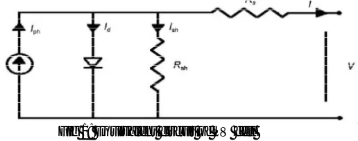
Equivalent circuit model of PV module is an important tool to understand the operation of device and the dynamic interactions between parameters. PV module is described using various mathematical equations and user friendly Matlab/Simulink environment is used to simulate the PV module. The ideal equivalent circuit of solar cell is a current source in parallel with a single diode. For the purpose of the electrical characteristics of a solar cell, it can be described by an electric circuit with only four components. The ideal solar cell consists of a single diode connected in parallel with a light generated current source, Iph. Rs and Rsh represent the
series and shunt resistance of solar cell. Usually the value of Rsh is very large and that of Rs is very small, hence they may be
So in order to increase the capability of the overall PV system, the solar cells are connected in series and parallel configurations to form solar modules and arrays [8].
Fig 1: Equivalent circuit of PV cell
From the theory of semiconductors and photovoltaic, following are the basic equations that mathematically describe the current– voltage relationship of the PV module.
According to equation (1) diode current ION can be given as:
= ( + ) −1 (1)
Where, Is is the saturation current, α=q/AKTCin which K is the Boltzmann’s constant (1.38 * 10-23 JK1), Tc is the cell temperature, q
is electron charge (1.6 * 10-19 C), A is the ideality factor, VPV and IPV are voltage and current generated by PV cells.
The output current (IPV) of PV cell is given as;
= − ( + ) −1 −
ℎ (2)
IL is light generated current depends linearly on solar irradiance is mentioned in below equation:
= + − (3)
Where, Iscis cell short circuit current, Ki is temperature coefficient of Isc, Tref is cell reference temperature, and G is the solar
radiation.
The cell saturation current Is varies with cell temperature is shown as:
= − (4)
Where, IRS is the cell reverse saturation current, Eg is the band gap for semiconductor used in cell.
[image:4.612.173.437.494.615.2]The PV system capability can be increased by forming a PV module. This can be done by arranging number of PV cells together in series and parallel configuration which is shown in Fig.2 and encapsulated transparent materials to protect from harsh environment.
Fig 2: Equivalent circuit of PV array
Below equation shows the output current of PV module:
= − − −1 −
ℎ − (5)
Where, Ns and Np are the number of cells connected in series and parallel.
III.PROPOSED MPPT TECHNIQUE
characteristics of PV modules. These techniques provide fast and powerful computational solution to the problem of MPPT. In recent years, much research has been done on the use of adaptive neuro fuzzy inference systems (ANFIS) to track the maximum power point (MPP) of PV power generators. ANFIS systems are actually fuzzy inference systems tuned by neural networks. Thus, they combine the computation power of neural networks with the reasoning capability of fuzzy inference systems. In addition, they can automate the generation of fuzzy rules. Fig.3 depicts the block diagram of the proposed MPPT Controller. The objective of the controller is to determine the duty cycle, D, of the converter, by which the converter delivers the maximum attainable power to the load at any given temperature and irradiance. Controller generates PWM signal for the converter. The first part of the controller, Adaptive Neuro-Fuzzy Inference System (ANFIS), works as a reference model of the PV array and finds the suitable maximum voltage under a given temperature and irradiance while the FL controller produces the change of D by comparing the maximum voltage of reference model and the output voltage of the PV array.
Fig 3: Proposed MPPT Controller
A. Fuzzy Inference System (FIS)
Every FIS model is composed of three stages. In fuzzification stage, FIS maps the input variables to linguistic variables by determining the membership function (MF). After that, the IF-THEN rules are p provided to set a relationship among the inputs and the output, which is called rule evaluation. Then, in defuzzification the linguistic variables are converted to a crisp value of output. The parameters are tuned according to the input-output data of model.
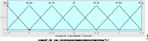
In general, the fuzzy logic controller (FLC) is a FIS. The first part is fuzzification, which is a procedure of converting numerical inputs into linguistic variables according to the degree of membership function. The linguistic variables are defined as Negative Large (NL) ,Negative Medium (NM), Negative Small (NS), Zero (Z), Positive Small (PS), Positive Medium (PM) and Positive Large (PL). Each of them shows the fuzzy Large (PL). Each of them shows the fuzz data, as can be seen in Fig.4.
Fig 4:Membership function for FLC
The membership functions can be an arbitrary curve whose shape can be defined as a function that suits designers in approaching of simplicity, convenience, speed, and efficiency. Membership function for ANFIS and FLC are chosen Gaussian and triangular function respectively. The Gaussian membership function has the advantage of being smooth and nonzero at all points while the triangular membership function is used because of its simplicity.
It is a general view that if the number of membership function between the defined ranges is larger, then the possible rules increases and the response will be worthy. It is desirable to increase the rules for a proper response but after increasing the rules to a certain limit (49 rules in this case) there is no need to go beyond since the response does not change appreciably.
There are two common inputs for FLC, error ‘E’ and change in error ‘ΔE’, as follows,
E = V - V (6)
[image:5.612.153.465.489.577.2]The output of FLC generally isΔD, change in duty ratio, of the power converter. Table 1 shows the second stage of FLC known as the rule based table lookup. The rules explain the relationship among E, ΔE and ΔD represented by IF- THEN sentences. For example, if error is negative small (NS) and change of error is positive small (PS) then change of duty cycle will be zero (Z). The third level of FLC is defuzzification in which numerical variables and result will be produced to provide the analog signal that controls MPP.
Table 1: Fuzzy Rules
E\ΔE NL NM NS Z PS PM PL
NL NL NL NL NL NM NS Z
NM NL NL NL NM NS Z PS
NS NL NL NM NS Z PS PM
Z NL NM NS Z PS PM PL
PS NM NS Z PS PM PL PL
PM NS Z PS PM PL PB PL
PL Z PS PM PL PL PL PL
B. Adaptive Neuro-Fuzzy Inference System (ANFIS)
The neuro-fuzzy inference is a combination of ANN and FL. The ANN identifies the patterns and conforms to them to deal with altering environments. On the other hand, the fuzzy inference systems (FIS) combine the human knowledge and carry out the inference and process of decision making. Two common fuzzy models, the Mamdani and Takagi Sugeno-Kang (TSK), are defined for FIS[14]. The ANFIS is only able to use the TSK fuzzy model due to its high calculative efficiency, adaptive techniques and built in optimum. The controller provides smoothness in convergence because of the fuzzy TSK inference and adaptability as a result of ANN back propagation algorithms.
C. ANFIS with PV System
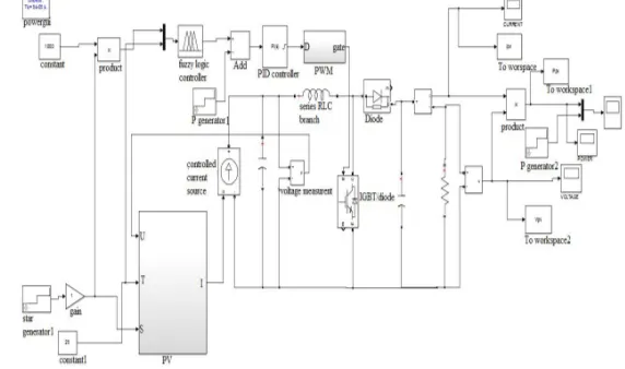
[image:6.612.153.439.538.707.2]In this paper a new MPPT method, Adaptive Neuro Fuzzy Inference system (ANFIS) is used for tracking MPP, which is described in this section. The proposed Matlab/Simulink model of ANFIS based maximum power point tracking controller is depicted in Fig.5. Irradiance level and operating temperature of PV module are taken as the input training data set for the ANFIS. The ANFIS reference model gives out the crisp value of maximum available power from the PV module at a specific temperature and irradiance level. At the same temperature and irradiance level, the actual output power from the PV module, is calculated using the multiplication algorithm of sensed operating voltage and current. Two powers are compared and the error is given to a proportional integral (PI) controller, to generate control signals. The control signal generated by the PI controller is given to the PWM generator. The PWM signal is generated using high frequency of carrier signal as compared to the control or modulating signal. The frequency of carrier signal used is 50 kHz. The generated PWM signals control the duty cycle of DC–DC converter, in order to adjust the operating point of the PV module.
D. Tuning of ANFIS
Using the Matlab/Simulink model of PV module, the operating temperature is varied from 15o C to 65o C in a step of 5o C and the solar irradiance level is varied from 100 W/m2 to 1000 W/m2 in a step of 50 W/m2, to get the training data sets for ANFIS. Maximum available power for each pair of training data is recorded. In total 209 training data sets and 1000 epochs are used to train the ANFIS. By using given input/output data set, the ANFIS constructs a fuzzy inference system (FIS) whose membership function parameters are tuned using the hybrid optimization method of training the FIS. The hybrid optimization method is a combination of the least squares type of method and the back propagation algorithm. It depicts that the ANFIS output closely matches to the actual output of module even at 6% of training error. The structure of ANFIS, generated by the Matlab code is a five layer network. It has two inputs (irradiance level and operating temperature), one output and three membership functions for each input.Nine fuzzy rules are derived from six input membership functions. These rules are derived according to the input and output mapping, so as to produce maximum output power for each value of input temperature and irradiance level.
Parameters used in ANFIS
Reference value of irradiance (Gref): 1000W/m2
Step variations of irradiance (Gstep):50W/m2
Reference value of temperature (Tref):65oC
Step variations of temperature (Tstep):5oC
IV. RESULTS
[image:7.612.151.460.353.509.2]An effective Grid connected PV system through MPPT method named Adaptive Neuro-Fuzzy Inference System(ANFIS) with reduced components has been considered initially and then wavelet transforms are introduced. It can be seen that the model with wavelet transforms and ANFIS provide better results compared to without wavelet.
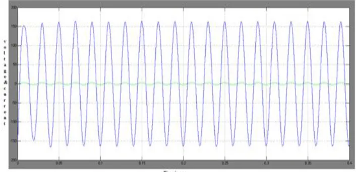
Fig 6: Three phase waveform of the proposed i.e., Grid voltage, Currents & Output Voltage, Currents of the Inverter
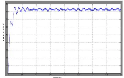
[image:7.612.128.481.546.717.2]Fig 8:Dc link Voltage of the proposed ANFIS PV model
[image:8.612.170.442.247.390.2]Fig 9:Power from ANFIS based PV array with and without Wavelet
Table 2: THD Data for Grid Current
S.NO Grid Connected at different considerations Before LC Filter Igabc(%)
After LC Filter Igabc(%)
1. Constant DC source [7] 2.14 0.41
2. ANFIS based PV array without Wavelet 2.63 0.83
3. ANFIS based PV array with Wavelet 1.99 0.68
To simulate the performance of the grid connected PV system with advanced MPPT technique ANFIS. The obtained output voltage of the PV array is 30V to 40V and output current is 1.2A to 6A.Other values are considered as follows: DC link capacitor as 400µF, line resistance as 0.1 and inductance is 10mH.The grid voltage is 440V with 50Hz frequency. From Fig.6 the three phase grid
voltages and currents that are transformed into the control inputs and are again modified by using LC filter according to grid requirements. All the simulations are done in the widely using Matlab/Simulink. When the system is simulated at different atmospheric condition where the value of solar irradiation is considered as 0.25 kW/m2, 0.5 kW/m2, 0.75 kW/m2, 1kW/m2 and the temperature as 30 degrees some fluctuation occur due to the nonlinearity of PV systems.
filtering at different sources in all the three considerations. The data given in Table 2 shows that high quality grid current with limited THD (%) was produced by ANFIS based grid connected PV system with wavelet.
V. CONCLUSIONS
In this paper, a new MPPT technique with wavelet transforms was presented and Matlab/Simulink models for grid connected PV system with proposed MPPT technique ANFIS has been introduced. The objectives of controller were reached and the performance of the models ANFIS based grid connected PV systems with and without using wavelet transforms has been compared. The results of proposed method after comparison between both with and without wavelet and it is seen that Grid connected PV system with ANFIS and wavelet provides better results, as it gives the better %THD reduction i.e. 18.07% over the Traditional Grid Connected PV Systems. By observing both analysis and simulation, it has been proven that the obtained controller meets all the grid code requirements.
REFERENCES
[1] TrishanEsram and Patrick L.Chapman, “Comparison of Photovoltaic Array Maximum Power Point Tracking Techniques,”IEEE Transactions on Energy Conversion, Vol. 22, No. 2, June 2007.
[2] E. Koutroulis, K. Kalaitzakis, and N. C. Voulgaris, “Development of a microcontroller-based, photovoltaic maximum power point tracking control system,” IEEE Trans. Power Electron., vol. 16, no. 1, pp. 46–54, Jan. 2001.
[3] T. Esram and P. L. Chapman,“Comparison of photovoltaic array maximum power point tracking techniques,” IEEE Trans. Energy Conversion., vol. 22, no. 2, pp. 439–449, Jun. 2007
[4] M.BalajiNaik, Dr.P.Sujatha,”Adaptive Fuzzy and Neuro-Fuzzy Inference Controller Based MPPT for PV sytems”,IRJET,vol 2,issue 8,pp.693-701,Nov-2015. [5] Ravinderkumarkharb,S.L.Shimi,S.Chatterji,Md.Fahim Ansari, “Modeling of solar PV module and maximum power point tracking using ANFIS,” Renewable
and Sustainable Energy Review 33(2014) 602-612.
[6] A.M.Zaki, S.I.Amer, M.Mostafa,”Maximum Power Point Tracking for PV System Using Advanced Neural Networks Technique”, IJETAE,vol 2,issue 12,pp.58-63,Dec-2012
[7] Jin-Woo Jung,NgaThi-ThuyVu,DongQuangDang,TonDucDo,”A Three-Phase Inverter for a Standalone Distributed Generation System:Adaptive Voltage Control Design and Stability Analysis”,IEEETrans.Energy Conversion,vol.29,no.1,pp.46-56,March.2014.
[8] Quoc-Nam Trinch,Hong-HeeLee,”An Enhanced Grid Current Compensator for Grid-Connected Distributed Generation Under Nonlinear Loads and Grid Voltage Distortions”,IEEEtrans,Industrial Electronics,vol.61,no.12,pp.6528-6537,Dec 2014.
[9] Weidong Xiao, Nathan Ozog and William G. Dunford, “Topology Study of Photovoltaic Interface for Maximum Power Point Tracking,”IEEE Transactions on Industrial Electronics, Vol. 54, No. 3, June 2007.
[10] ZhengShicheng, Liu Wei, “Research and implementation of photovoltaic charging system with maximum power point tracking,” IEEE, 2008.
[11] ZengLiu,JinjunLiu,YalinZhao,”A Unified Control Strategy for Three Phase Inverter in Distributed Generation”,IEEEtrans,Power Electronics,vol.29,No.3, pp.1176-1191,March 2014.
[12] Yun-Pam Lee, En-Chi Liu, and Huang-Yao Huang, “A Small Scale Solar Power Generation, Distribution, Storage, MPPT and Completed System Design Method,” IEEE, 2010.
[13] SoerenBae ,khoejKjaer, John K. Pedersen, et al., “Power Inverter Topologies for Photovoltaic Modules – A Review,” IEEE, 2002. [14] V. Salas, M. J. Manzanas, et al., “The Control Strategies for Photovoltaic Regulators Applied to Stand-alone Systems,” IEEE, 2002.
[15] S. Ozdemir, N. Altin and I. Sefa, “Single Stage Three-Level MPPT Inverter for Solar Supplied Systems,” International Symposium on Power Electronics, Electrical Drives, Automation and Motion, 2012.