Technology (IJRASET)
©IJRASET: All Rights are Reserved
344
Design of Computer Vision Intelligent System for
Lane Detection
Sanket J.Mankar1, Manoj Demde2, Dr. Prashant Sharma3
1
M.tech , 2Prof. , Electronics and telecommunication
Priyadrshini College of engineering 3
MIET, Gondia
Abstract: The Intelligent vehicle is an interesting area of research now a day which can be used for the intelligent transport system. It can help to maintain lane and changing lanes travelling lane information necessary to provide smart vehicle to achieve a smooth, safe driving. The system is developed to detect the lanes on the road along with the departure system. The concept in such systems works towards development of the lane departure warning system based on video image processing techniques for Night light, Rainy weather , broken lane and normal road conditions. Due to the growing traffic and improper driving one may suffer from an accident. The proposed system will be helpful to determine the lane in which the car/bus etc should be driven. It is a tedious job to obtain the proper lane in the night light, in broken edges of the lane also in the rainy season. The main objective of the system is to avoid this problem .To deal with this difficulty an (intelligent system) i.e. neural network/fuzzy logic is used in the proposed system which is not included in the existing system .
Keywords: Intelligent system, lane detection, departure warning, video image processing
I. INTRODUCTION
A present challenge of the automotive industry is to design an economical advanced driver assistance systems. ADAS will be able to increase traffic safety and driving comfort. Vision is the most used human sense for driving; some ADAS features rely on visual sensors. Specifically, lane departure Warning system can be obtained by detecting the lane markings on the road by the use of a forward- facing camera and computer vision techniques. This method focus on this problem, which is the first addressed in the field of Advance driver assistance system. It is a difficult and not yet completely solved problem due to rainy conditions tremendous contrast variations, vehicles occluding the marks, broken markings, vehicle ego-motion, foggy conditions etc.
The lane image capturing is one of the most crucial aspects in the edge detection and lane recognition, which can provide the necessary information when the vehicle is in motion. We take advantage of the information to complete automatic drive reliably and safely. The application background is the highway or the standard high-grade highways or the city roads. According to the lane of the particular road, the research on the algorithm of lane snatch will be launched in this project. So it will offer some effective technologies for the stray warning system of automated driving. Lane detection is the process to determine the lane markers on the road and then present these locations to an intelligent system. In this system, intelligent vehicles cooperate with smart infrastructure to achieve the system in favor of environment and better traffic conditions. The applications of a lane detecting system could be as simple as showing out lane locations to the driver on an external display, to more complex tasks such as predicting a lane change in the instant future so that it can avoid collisions with other vehicles. Some of the interfaces used to detect lanes include cameras, high definition images or laser range images.
II. LITERATURE SURVEY
Technology (IJRASET)
©IJRASET: All Rights are Reserved
345
III. METHODOLOGY
The methodology implemented can be explained by using the fig given below.
Fig.(a) Methodology
A. Image Captured By Camera
Basically captured image is selected from the video which is captured by the camera mounted on the vehicle. The captured image is called as the RGB image or original image. Each image from the video is sequentially processed in the following steps.
B.RGB To Gray Conversion
As it is not possible to process on the RGB image, it is required to convert the RGB image into the gray scaled image .The main advantage of the gray scaled image is , it requires less time to process.
C. Filtering
Noise in the given image may result in the reduction of the quality of the image, which may cause impairments in extracting the information from the given image. To avoid this we use filters like median, 2D FIR etc
D. Resizing
Resizing (or retrospective sizing), is specially a conservation treatment, a special instance of surface sizing. The purpose behind the resizing is to impart the strength to the sheet and to provide the dimensional stability.
E. Region Of Interest
The term region of interest is generally abbreviated as ROI. This term makes clear that the region which is of no use should be eliminated from the original image so that the speed of the operation will get increased. In proposed system the region of interest is only the road showing the lanes.
F. Histogram Equalization
This is an image processing technique used for the contrast adjustment. This process helps to acquire a large contrast to the less contrast part and vice versa. More the contrast value is closer, more will be the process helpful. .eg.
Fig.(b) Normal and equalized histograms
G. Thresholding
Technology (IJRASET)
©IJRASET: All Rights are Reserved
346
the road image.
H. Edge Detection
Sharp contrast between the road surface and the painted lines (lane markings) determines the edges in the images .Therefore it is necessary to have an edge detector in order to determine the location of the lane boundaries. It may reduce the amount of learning data [2].
I. Hough Transforms
Hough transform is use to detect the lines. In fact the standard Hough transforms searches for the lines in the given image [2].
IV. RESULTS
This section of the paper will depict the outputs of the system. However our prime aim is to detect the lanes on the road, it is shown how we have reached to the outputs.and hence the output is shown stepwise. Outputs for night light condition and the Rainy condition are shown below.
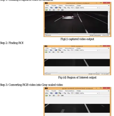
A. Outputs for Night Light Condition
Step 1: Loading a captured video in Simulink
Fig(c) captured video output Step 2: Finding ROI
Fig (d) Region of Interest output
Step 3: Converting RGB video into Gray scaled video
[image:4.612.42.432.290.688.2] [image:4.612.145.418.291.560.2]Technology (IJRASET)
©IJRASET: All Rights are Reserved
347
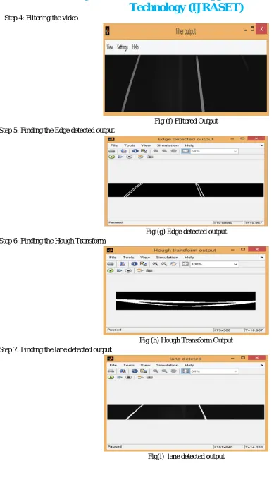
Step 4: Filtering the video
Fig (f) Filtered Output Step 5: Finding the Edge detected output
Fig (g) Edge detected output Step 6: Finding the Hough Transform
Fig (h) Hough Transform Output Step 7: Finding the lane detected output
[image:5.612.42.431.57.737.2]Technology (IJRASET)
©IJRASET: All Rights are Reserved
348
B. Outputs for Rainy Condition
Step 1: Loading a captured video in Simulink
Fig (j) Captured video Step 2 : Finding ROI
Fig(k) Region of Interest output
Step 3: Converting RGB video into Gray scaled video
Fig (l) Gray scale converted output Step 4: Filtering the video
[image:6.612.97.422.110.370.2] [image:6.612.41.428.127.584.2] [image:6.612.176.419.404.698.2]Technology (IJRASET)
©IJRASET: All Rights are Reserved
349
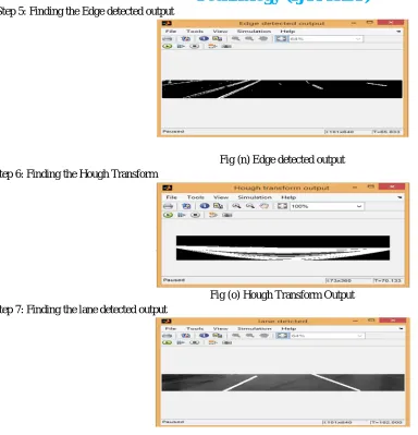
Step 5: Finding the Edge detected output
Fig (n) Edge detected output Step 6: Finding the Hough Transform
Fig (o) Hough Transform Output Step 7: Finding the lane detected output
Fig (p) Lane detected output (Rainy Condition)
V. CONCLUSION
A real time lane detection algorithm based on video sequences taken from a vehicle driving on highway was proposed. As mentioned above the system uses a series of images. Since the lanes are normally long and smooth curves, we consider them as straight lines within a reasonable range for vehicle safety. The lanes were detected using Hough transformation with restricted search area. Along with the Hough Transform, Hough lines plays an important role in detecting the roads. The proposed lane detection algorithm can be applied in both night light condition and rainy day condition. lane. Some changes in the weather conditions may reduce the system reliability.
VI. ACKNOWLEDGEMENT
I would like to take this opportunity to express my gratitude to all those who extended their support and have guided me to complete this paper. First and foremost, I would like to thank Prof. M. K. Demde for his kind support and encouragement. Also I am thankful, Department of Department of Electronics &Telecommunication Engineering, for their motivation, inspiration and co-operation towards completion of this paper. Finally, I sincerely thank to my parents, family and associates who provide me advice and financial support. The product of this paper would not have been possible without all of them.
REFERENCES
[image:7.612.47.431.72.471.2]Technology (IJRASET)
©IJRASET: All Rights are Reserved
350
[3] Xin Liu, Bin Dai, Jinze Song, Hangen He Bo Zhang,” Real-time Long-range Lane Detection and Tracking for Intelligent Vehicle” Sixth International Conference on Image and Graphics 2011
[4] Jegan R. Mani, N. D. Gangadhar, Viswanath K.” A real-time video processing based driver assist system” Volume 9, Issue 1, April 2010
[5] Guoliang Liu, Florentin W¨org¨otter and Irene Markeli, “Combining Statistical Hough Transform and Particle Filter for RobustLane Detection and Tracking” [6] B. M, Broggi, “GOLD: A parallel real-time stereo Vision system for generic obstacle and lane detection”, IEEE Transactions on Image Processing, 1998,pp.
4-6.
[7] C. Kreucher, S. K. Lakshmanan, “A Driver warning System based on the LOIS Lane detection Algorithm”, Proceeding of IEEE International Conference On Intelligent Vehicles. Stuttgart, Germany, 1998, pp. 17 -22.
[8] Pomerleau D. and Jochem,”Rapidly Adapting Machine Vision for Automated Vehicle Steering”, IEEE, 1996.