A Bidirectional Converter Using Fuzzy Controller
Sasikumar S1, Krishnamoorthi K2, Sivakumar R3 1
Research Scholar, Department of Electrical Engineering, Sona college of Technology, Salem, India
2
Associate Professor, Department of Electrical Engineering, Sona college of Technology, Salem, India
3
Assistant Professor, Department of Communication Engineering, AVS college of Engineering, Salem, India
Abstract: This paper presents the fuzzy controller design of a bidirectional converter based on intelligent fuzzy model. The topology circuit of this bidirectional is a combination of a buck converter and a boost converter. The intelligent fuzzy model of the bidirectional converter operated on buck mode and boost mode are derived respectively. The state-feedback gains are obtained by using Lyapunov stability theorem. Simulation results demonstrate with the intelligent fuzzy approach is better than the perturbation and observation method.
Keywords: bidirectional converter; fuzzy; perturbation and observation
I. INTRODUCTION
The development of bidirectional dc-dc converters has recently become increasingly important for clean-energy vehicle applications because battery-based energy storage systems are required for cold starting and battery recharging. Bidirectional converters transfer power between two dc sources in both directions. However, back-up power from the battery is supplied using a bidirectional converter, which is employed in many uninterrupted power supplies (UPS), the front-end stage for clean-energy sources, and dc motor drivers circuits. The dc back-up energy system typically consists of numerous low-voltage-type batteries. Although series strings of storage batteries can provide a high voltage, slight mismatches or temperature differences cause charge imbalance when the series string is charged as a unit . Charge equalization cycles must be employed to correct this imbalance; however, conventional approaches to this process stress batteries, shorten their life, and are limited to a low capacity power. The current extensive operation of batteries in parallel strings is based on the desire of enhancing the redundancy of the power supplied by a battery, and the problems caused by series strings of storage batteries can be alleviated . However, output voltage remains low in this parallel connection configuration. Therefore, a highly efficient bidirectional dc-dc converter with high voltage diversity is a key component for batteries connected in parallel. Bidirectional dc-dc converters with transformer-based structures are the most common topologies and soft switching techniques are generally applied to reduce corresponding switching losses. These mechanisms with isolated transformers have high conduction losses because four to nine power switches are required. Many applications call for high step-up converters that do not require isolation , such as the front-end converter with dual inputs. Accordingly, practical implementation is complex and costly. Switched-capacitor dc-dc converters have attracted much attention as an alternative method for providing bidirectional power flow control. However, increased switching loss and current stress are the critical drawbacks, and the primary challenge is to design a circuit that has few switch devices and capacitors. Generally, the bidirectional converter in the UPS must generally boost 48V to 400V, which is appropriate for eightfold step-up voltage gain. Zhao and Lee developed a family of highly efficient, high step-up dc-dc converters by adding only one additional diode and a small capacitor. This capacitor can recycle leaked energy and eliminate the reverse-recovery problem. In this approach, the magnetic core can be regarded as a fly back transformer and most energy is stored in the magnetic inductor. Inaba et al. introduced a two-quadrant pulse-width modulation (PWM) chopper-type dc-dc converter that uses a coupled inductor. In this technique, only three switches were needed to achieve bidirectional power flow. Although an additional snubber capacitor was utilized successfully to clamp spike voltage, a 250V voltage-rated switch was employed in a low-voltage (36V) side circuit, resulting in considerable conduction loss because a switch with a high was used. Coupled inductors with a low-voltage-rated (80V) switch and a passive regenerative snubber circuit was adopted to achieve high-voltage gain with a 400V output high-voltage; this gain is superior to that in Unfortunately, the non-isolation topologies in only control unidirectional power flow. Moreover, bidirectional dc-dc converters with transformer-based structures are not suitable for use in power sources with wide voltage variations because magnetizing currents are difficult to manage, large copper losses occur on the low-voltage side (LVS), and all energy is transferred from the large core. Therefore, the number of devices must be minimized and good transformer performance ensures the high-efficiency of a bidirectional converter.
and step-down functionalities. This circuit include soft switching, synchronous rectification, and voltage clamping to reduce switching and conduction losses caused by utilizing a low-voltage-rated device with a small RDS (on). The windings in the coupled
inductor function as a bidirectional magnetic switch controlling energy release or storage. Since the slew rate of current change in the proposed coupled inductor is restricted by the leakage inductor, the current transition time to both sides easily facilitates soft switching. The problems of saturation and imbalance of the magnetizing current for a variable voltage source are therefore eliminated. Moreover, a full copper film and few primary winding turns reduce the size, cost, and copper loss of the coupled inductor; the corresponding voltage gain, which is related to the turns ratio and duty cycle, is higher than that in previous work. This paper presents the design and implementation of a non-isolated bidirectional DC/DC converter with high speed of response, low error for DC power system applications. The topology of this circuit is a combination of a buck converter and a boost converter. In the circuit, a DSP chip realizes almost all of the functions, such as circuit protection, generation of pulse-width modulation (PWM) signals and A/D conversion, etc. If the load voltage drops below the set point, the converter operates in buck mode to regulate the load voltage. If the load power is higher than the desired value and the voltage at the battery side is low, the converter operates in boost mode. If the load voltage and the battery voltage are regulated within the desired ranges, the converter operates in idle mode. Finally, we design and implementation of a 100W bidirectional converter. Intelligent fuzzy control is applied to the bidirectional DC/DC converter to verify the feasibility and characteristic of the circuit.
[image:3.612.173.443.294.450.2]II. BIDIRECTIONAL CONVERTER
Fig. 1. Circuit of the bidirectional converter
In this study, general configuration of battery charging system is shown in Fig. 1. This system includes PV arrays as the source, boost converters combination as the main converter, bidirectional converter with inductor coupled, and battery [5]. Photovoltaic system that used on this study is used Neural Network Multi Model (NNMM) Maximum Power Point Tracking (MPPT) [4, 6]. This study uses two level converters for PV system which correlated with battery. They are boost converter as MPPT, and bidirectional converter with coupled inductor as inductor to manage the battery charge and discharge current. Bidirectional converter system with coupled inductor is more efficient than common bidirectional converter.
System has the following four parts circuit: an LVS, a clamped circuit, a middle circuit; and, a high-voltage side (HVS). The symbols used are as follows: VL and VH are the voltages at the LVS and HVS, respectively; LP and LS represent individual inductors
on the primary and secondary sides of the coupled inductor (Tr), respectively, where the primary side is connected to a battery
module; S1 and S2 are the low-voltage switch; and, S3 and S4 are the high-voltage switch. When power flows from the HVS to the LVS, the circuit works in buck mode to recharge the battery from the HVS or by absorbing regenerated energy. In the other power flow direction, the circuit works in boost mode to keep the HVS voltage at a desired level. The following assumptions simplify converter analyses. 1) All MOSFETs, including their body diodes, are assumed ideal switching elements. 2) The conductive voltage drops of the switch and diode are neglected. The converter design and analytical procedures in buck and boost modes are described in the following subsections.
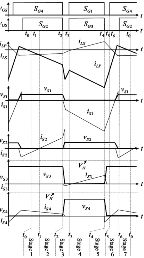
A. Buck Mode
directions. The coupled inductor (Tr) can be modelled as an ideal transformer that has magnetizing inductors ( Lm1 and Lm2 ) and
leakage inductors ( Lk1 and Lk2 ). The turn’s ratio (N) and coupling coefficients (k) of this ideal transformer are defined as
Where N1 and N2 are the winding turns on the primary and secondary sides of the coupled inductor (Tr), respectively. Because
voltage gain is insensitive to the coupling coefficient and a clamped capacitor C1 is appropriately selected to completely absorb inductor energy leakage [10], [11], the coupling coefficient is simply set at 1 to obtain. Lm1 =LP, Lm2 =LS and N= via Eqs.
[image:4.612.192.422.241.653.2](1) and (2).
Fig. 2. Characteristic waveforms of bidirectional converter in buck mode.
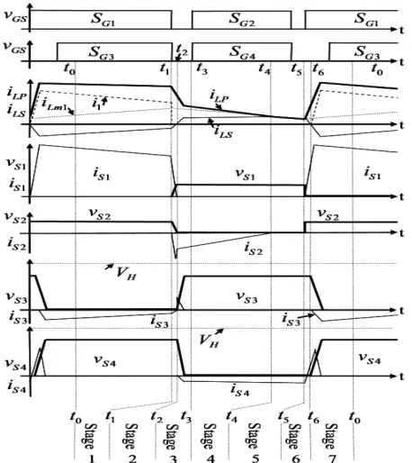
B. Boost Mode
Fig. 3. Characteristic waveforms of bidirectional converter in boost mode.
III. FUZZY CONTROLLER FOR DC TO DC BUCK CONVERTER
Fuzzy controllers fulfil the same tasks like a classic P.I.D. controller. Fuzzy controller differs from the classic one in that it manages the control complex space in a heuristic manner. However, the fuzzy controller can approximate, with any precision level, linear and non- linear control functions. In many situations is easier to obtain a fuzzy controller with high performance than a classic P.I.D. controller with same performances [11]. Implementation of a fuzzy controller implies control function codification in fuzzy rules set which operates on fuzzy sets resulted in the fuzzification of the input and output domains. Usually, a P.I. fuzzy controller has two input s and one output. Fuzzy controller in this application consists in two fuzzy sub- controllers (with one input and one output), one for the proportional component and one the second for the integral component. One chooses this option due to simplified definition of the inference rules and an easier tuning process. Alongside these advantages, this configuration needs a shorter calculus time. First fuzzy controller is P type with one input (output voltage error) and one output (duty cycle variation). There are 4 membership functions both for input and the output. These membership functions are presented in figures 3.a and 3.b . Linguistic terms for input (output voltage error) were considered NAe, NMe , PMe and PAe and for output (duty cycle variation) YNG, YNMS, YPMS, YPG. Inference rules were defined as: IF error is NAe THAN output is YNG; IF error is NMe THAN output is YNMS; IF error is PMe THAN output is YPMS; IF error is PAe THAN output is YPG. By this way results control function in figure 3.c.Fuzzy controller for the integrative component considered also 4 membership functions for input and for output. Membership functions were considered trapezoidal, like in figures 3.d and 3.e. Linguistic terms for the input (output voltage integral) were considered NAie, NMie , PMie and PAie and for output (duty cycle variation) YNG, YNMS, YPMS, YPG. Inference rules were defined as: IF error is NAie THAN output is YNG; IF error is NMie THAN output is YNMS; IF error is PMie THAN output is YPMS; IF error is PAie THAN output is YPG. By this way results control function in figure 3.f. closed loop converter system was implemented in SIMULINK in figure 4. This kind of fuzzy controller was proposed by authors in [7]. In the definition of membership functions and inference rules one aimed to obtain a higher slope for the control surface near origin, both for proportional and integrative component. This fact can be observed for the control surfaces in figures 3.c and 3.f. In the operation of APF, APF should correctly trace the reference so that the source current will be free from harmonic. This APF will draw small power from the source to compensate the switching loss and capacitor losses, so the DC voltage of each converter should be balanced.
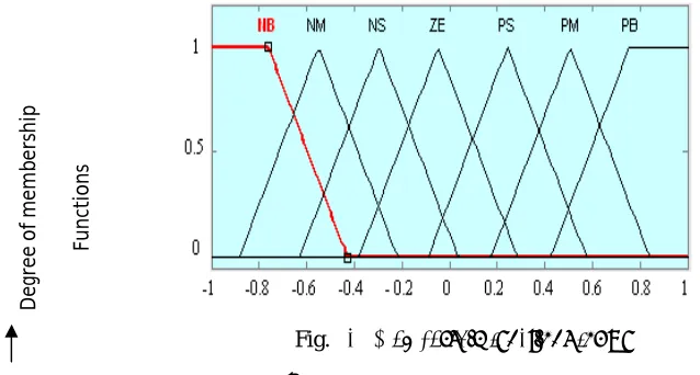
[image:5.612.192.421.84.341.2]Seven fuzzy sets (NB, NM, NS, ZE, PS, PM, PB) for each input and output variables. Triangular membership function is used because of its simplicity
Implication using Mamdani-type min-operator. Defuzzification using the centroid method.
The conversion of fuzzy values is shown by the membership functions.
Fig. 4a Membership functions for e
Fig. 4b Membership functions for Δe
Voltage Error (e)
D
eg
re
e
o
f
m
em
b
er
shi
p
D
eg
re
e
o
f
m
em
b
er
shi
p
Fig. 4c Membership functions for Δu
[image:7.612.113.432.107.278.2]The Rule base stores the linguistic (fuzzy) control rules required by the rule evaluator (decision making logic), the 49-rules used are presented in Table 1.
Table 1 Rule base of fuzzy controller
∆e/e NB NM NS ZE PS PM PB
NB NB NB NB NM NM NS ZE NM NB NB NM NS NS ZE PS NS NB NM NS NS ZE PS PM ZE NM NS NS ZE PS PS PM PS NM NS ZE PS PS PM PB PM NS ZE PS PS PM PB PB PB ZE PS PM PM PB PB PB
This estimated magnitude of peak-current multiplied with an output of unit sine vector determines the reference currents. The reference currents are compared with actual source currents to generate VSI-switching pulses using PWM-current controller. This controller handles nonlinearity and it is more robust. It facilitates reduction of ripples in dc-link capacitor of the PWM-inverter.
A. Hysteresis Controller
For the PWM-voltage source inverter; hysteresis current controllers are configured for each phase. Each current controller directly generates the switching signal of the three (a, b, c) phases. If the input current is positive and error current e(t) is between the desired reference current iref(t), the load current iload(t) exceeds the upper hysteresis band limit (+h) and hence the upper switch of the
inverter arm is in OFF state and the lower switch is in ON state. Thus the current starts decreasing. Similarly, if the error current e
(t) crosses the lower limit of the hysteresis band (-h), the lower switch in the inverter arm turns OFF and the upper switch switches ON. Now, the current gets back into the hysteresis band and the cycle goes on repeating.
IV. BATTERY REQUIREMENT FOR AUTOMOTIVE APPLICATION
Mainly Nickel-Metal hydride (NiMH) and Lithium-ion batteries are used in vehicular application due to their characteristics in terms of high energy density, compact size and reliability. The battery is being recharged by the regenerative capabilities of the electric motors which are providing resistance during braking helping to slow down the vehicle. The lithium-ion battery has been proven to have excellent performance in portable electronics and medical devices .The lithium-ion battery has high energy density,
high specific power of 300 W/kg, high specific energy of 100 Wh/kg, and long battery life of 1000 cycles. These excellent characteristics give the lithium-ion battery a high possibility of replacing NiMH as next-generation batteries for vehicles.
V. SIMULATION RESULT AND ANALYSIS
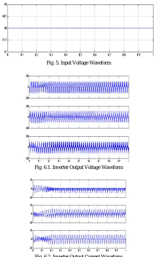
The test consists of a three phase AC source of voltage 4500 v (peak) and 50 Hz frequency to a nonlinear diode rectifier load through a source and line combined reactance of 15mH/Phase. The R-L Load on the DC side of diode rectifier is about 20 ohm and 0.1 mH. The simulation results of the proposed multilevel inverter based SAPF compensation.
[image:8.612.148.458.190.707.2]Fig. 6 shows the single phase voltage and current waveforms of system with SAF.
Fig. 5. Input Voltage Waveform
Fig. 6.1. Inverter Output Voltage Waveform
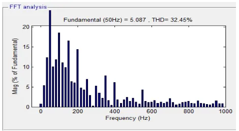
The THD in source current is about 2.28 % as shown in Fig.7.
Fig. 7. Harmonic Spectrum of Source Current of SAF
Thus, the multilevel inverter based SAPF successfully injected the power from hybrid system into the grid along with harmonic compensation.
VI. CONCLUSIONS
This paper presents modelling and analysis of a DC to DC buck converter (with a gain lesser one) by numerical simulation. Closed loop model was implemented in MATLAB/SIMULINK toolbox SIMPOWERSYS, and the controller is fuzzy type. This kind of controller was proposed by authors in [7] for a DC-to- DC boost converter. Good behaviour of the Buck converter studied in this paper proves the robustness of the fuzzy controllers. Fuzzy controller shows good stabilization qualities while it doesn’t needs to know the mathematical model of the Buck converter in the controller design process. Simplified version with two more simple controllers in parallel, one for the proportional component and one for the integrative component allows simplifying the inference rules definition and the controller tuning. Moreover, the calculus time for this configuration is shorter than the calculus time for a controller with two inputs and one output, due to a smaller calculus volume.
REFERENCES
[1] Amalin Rishma, A., Raja Rajeswari, P. and Sasikumar, M. (2012), “High Efficiency Modified Pulse Width Modulation Bidirectional Converters for Medium Power Drives,”IJAIEM, vol. 1, no. 2, pp. 94–100.
[2] Amin Mirzaei, Awang jusoh and Zainal Salam, (2012), “Design and Implementation of High Efficiency Non Isolated Bidirectional Zero Voltage Transition Pulse With modulated DC-DC converters,” Elsevier,Energy 47, pp. 358–369.
[3] Baburaja.C and Jayakumar, J., (2013) “Transformer less soft switching bi-directional DC-DC Chopper”,International journal of Engineering and Advanced Technology, vol. 2, pp.391-395.
[4] Chuan-Kuei Huang, Hsiau-Hsian Nien,Koan-Yuh Chang and Wen-Jer Chang, (2010) “An Optimal Designed RCD Snubber for DC-DC Converters,”Journal of Marine Science and Technology, Vol. 18, No. 6, pp. 901-906.
[5] Lee, D.Y., Kee, M. K., Hyun, D.-S. and Choy, I., (2003) “New zero-current-transition PWM DC/DC converters without Current Stress,” IEEE Trans. Power Electron., vol. 18, no. 1, pp. 95–104.
[6] Doo-Yong Jung, Sun-Hee Hwang, Young-Hyok Ji, Jung-Hyo Lee, Yong-Chae Jung and Chung-Yuen Won, (2013) “Soft-Switching Bidirectional dc-dc Converter with a LC Series Resonant Circuit,” IEEE Trans.Power Electron ,vol. 28, no. 4, pp. 1680– 1690.
[7] Hua, G., Leu, C., Jiang, Y. and Lee, F. C. ,(1994), “Novel zero-voltage transition PWM converters,” IEEE Trans.Power Electron., vol. 9, no. 2, pp. 213– 219. [8] Ho-Sung Kim, Myung-Hyo Ryu,Ju-Won Back and Jee-Hoon Jung, (2013) “High-Efficiency Isolated Bidirectional AC-DC Converter for a dc Distribution
System,” IEEE Trans.Power Electron., vol. 28, no. 4, pp.1642–1654.
[9] Hua Han, Yonglu Liu, Yao Sun,Hui Wang and Mei Su, (2014), “A Single Phase Current Source Bidirectional Converter for V2G Applications” Journal of Power Electronics, vol. 14, no. 3, pp. 458-467.
[10] Huiqing Wen and BinSu, (2015), “Reactive Power and Soft-Switching Capability Analysis of Dual -Active –Bridge DC-DC Converters with Dual-Phase-Shift Control” Journal of Power Electronics, vol. 15, no. 1, pp.18–30.
[11] Hyung-Min Ryu , (2014) “High Efficient High-Volatge MOSFET Converter with Bidirectional Power Flow Legs” ,Journal of Power Electronics, Vol. 14, No. 2, pp. 265-270.