Automatic Segmentation and Positioning of
Morphometric Points Intended for Cervical
Vertebrae.
N B Sambre1 V R Udupi 2 1,
Associate Professor , Department of E&TC,KIT, s College of Engineering, Kolhapur,Maharashtra,India 2
Principal, Maratha Mandal College of Engineering, Belgavi ,Karnataka, India2
Abstract: X rays are the most prevalent imaging examination that helps a doctor diagnose,monitor, and treat many medical
illnesses.In the detection of degenerative spinal disease, the knowledge of the vertebrae position, curve and alignment is
necessary. Active Appearance Model (AAM) as proposed by Cootes et al. is deformable model widely used for segmentation of grey scale images. The model is based on priory information learning of the shape and texture variation of a training set. A compact object class descriptor is formed, which can be used to search images for new object instances. In this paper, a brief description of the implementation of AAM along with positioning of the morphometric points on cervical vertebrae is given. Keywords: X ray, Cervical vertebrae, Segmentation, Morphometry, Active appearance model.
I. INTRODUCTION
The segmentation of vertebrae’s in x-ray images is very cr ucial in the identifying of abnormalities of the spine. X-ray images are affected by poor contrast of the subject, making it difficult to distinguish the subject from the background. An appropriate technique for object extraction is one of the most important investigation topics in the field of image processing. Radiologists use 6 point or a 9-point model to indicate points of importance along the vertebra boundary. Automatically detecting these landmarks on the vertebral boundary are significant in the pathology responsive shape-based recovery procedure. In our work of detecting and positioning the morphometry points, a 6 point model is used shown in fig 1.
Model-based approaches analyze different variations of an object using several samples of the object in a training set and finally compute a model based on the object variations. Active Shape Model and Active Appearance Model are such models. ASMs [4] are statistical models that are generated by examining a training set.ASM utilizes a search algorithm considering the grey level profile to adjust shape related with mean texture of the manually placed training points .The model parameters are adjusted based on correlation between ideal and current profile. To construct an AAM model, a training set of images is prepared in which landmark points have been marked on every image. A statistical model of the shape variation is formed by using these landmarks and Principle Component Analysis (PCA).A appearance model based on the texture (variation of the gray scale values) of image using mean shape, Delaunay triangles is computed. A combined model of the correlations between shape and texture, are computed. This model is placed near the object to initiate training .With adequate training examples this search model should be able to generate any image of normal anatomy. By finding the parameters which optimize the match between a synthesized model image and a target image all the structures represented by the model can be located. Obtaining a model by AAM is described the next section.
II. ACTIVE APPEARANCE MODEL : IMPLEMENTATION
The steps for implementation of AAM are briefed below
A. Shape Model
1) Align each shape of the sample on the first one;
2) Repeat until convergence:
3) Compute the mean shape,
4) Adjust the mean shape:
a) Related to size, an orientation and an origin by default,
b) To the first shape
c) Align each shape on the mean shape.
The alignedshape variations are modelled as an eigenvector matrix and a few parameters. After alignment we will get the result of shape model as shown in fig 3.
III. TEXTURE MODEL
To form the model the pixel information is captured using image warping and modelling pixel variation, using principle component analysis. The piecewise affine warp based on the Delaunay triangulation of the mean shape is used for the image warping. To obtain the texture information, from the training set, each shape is warped to a reference shape and sampled. Then the information of some pixel intensities is obtained by the interpolation and hereafter the analysis is same as that of the shapes. The result after applying the Texture model on training images is as shown in fig4
A. Joint shape-texture statistical model
The shape and texture models are combined together to build an improved model. The correlation between the shape and the texture model parameters is removed and the model representation is made more compact by a third principle component analysis which is performed on the concatenated shape and the texture model parameters of the training set to obtain the combined model parameters. The result of the combined model is as shown in the fig.5.
B. Applying aam
Obtained AAMmodel is used to find the modelled vertebras in a new image.
The mean shape computed in is now used in this step of searching the shape of vertebrae. The initial estimate is then positioned according to this information. After four iterations, fig.6, we get result of the segmentation. Segmented shape of the vertebrae obtained is shown in fig.7.The morphological points of interest i.e. anterior points, posterior points and the middle points of each cervical vertebra are identified by algorithm described in the next point.
C. Automatic 6-point localization
1) The method described by Samir Antani et al [1] first finds the four corners defining the vertebral boundary. These corners are defined as the most significant angles after eliminating all points along the vertebral boundary. These four points are tentatively labelled as 1, 3, 6 and 4.
2) Locations of points 2 and 5 are computed as the median points along the superior and inferior edges between points 3and 1 and 6 and 4 respectively.
3) The next step in the algorithm is to finalize labelling of points 3, 6, 4 and 1.
4) Point 3 is assigned as the point that makes an angle closest to 90 degrees between mid of inferior vertebra height and point 2.
5) Similar step is adopted for labelling points 6 along the inferior boundary.
6) Point 1is assigned as the point on the posterior side that makes an angle closest to 90 degrees between mid of posterior vertebra height and point 2.
Fig 1 shows a 6-point labelling used by radiologist. We describe the steps in the automatic 6-point localization method:
IV. RESULTS AND DISCUSSION
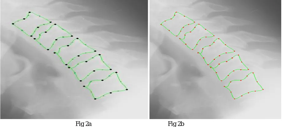
[image:4.612.95.558.288.496.2] [image:4.612.143.514.528.705.2]The results of the AAM implementation and placement of the anterior, middle and posterior morphometric points are illustrated in this section.
Fig 2a Fig 2b
Fig 2a, 2b: Black dots indicate the morphometric points and red dots are the landmark points.
-500 0 500
-300 -200 -100 0 100 200 300 400 PCA MODEL1
-200 0 200
-250 -200 -150 -100 -50 0 50 100 150 200 250 PCA MODEL2
-200 0 200
-300 -200 -100 0 100 200 300 PCA MODEL3
[image:5.612.116.551.95.210.2] [image:5.612.173.472.241.363.2]
Fig. 4a Fig.4b Fig.4c Fig.4d Fig 4a ,b,c,d show the Mean grey value ,first eigenv, second eigenv, third eigenv resp.
Fig.5 a Fig.5b Fig. 5c
[image:5.612.115.537.392.502.2]Fig.5a Original texture Fig.5b Texture of shape and texture model Fig. 5c Difference of a and b
[image:5.612.149.500.535.701.2]Fig. 6a Fig.6b Fig.6c Fig d Fig.6 a, Initial positioning of AAM model. Fig.6 b, c, d result of image scaling.
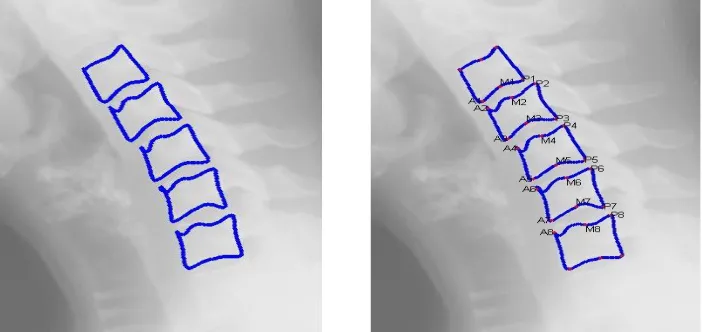
Fig.7 AAM Segmented vertebrae Fig.8 Automatic Positioning of anterior,middle and posterior points
V. CONCLUSION
The results of AAM implementation suggest that segmentation with the help of AAM is more fitting to X ray images as texture modelling is also considered in formation of AAM model. Computer assisted method show promising result for automatically locating of morphometric information related to location of vertebrae, vertebral boundary, shape of the vertebrae acquiring the variations in grey scale information & probing for the actual shape of the new vertebrae . In the future work, the placement of morphometric points can be utilised to find the distance between adjacent vertebrae which can help in the identification of disc space narrowing. We can extend 6 point morphometry to 9 point morphometry to identify anterior osteophytes, and subluxation.
REFERENCES
[1] Sameer Antani, L. Rodney Long, George R. Thoma “ Applying Vertebral Boundary Semantics to CBIR of Digitized Spine X-ray Images “Proc SPIE lectronic Imaging Science and Technology, Conference on Storage and Retrieval Methods and Applications for Multimedia. 2005;5682:98-107
[2] Sidi Ahmed Mahmoudi, Fabian Lecron, Pierre Manneback, Mohammed Benjellou Mahmoudi“GPUSegmentation of Images” Cluster Computing Workshops and Posters (CLUSTER WORKSHOPS), 2010 IEEE International Conference\Cheng- “SegmentationX RayImage and an Internet-Based Tool For Medical Validation”Thesis submitted to the Graduate School of the University of Maryland, College Park, forthe degree of Master of Science 2006
M.G.Cootes, J.E. Adams, “Automatic segmentation of on digitized radiographs using linked active appearance models”citeseerx.ist.psu.ed
[3] G Thoma,SAntani, “Content-Based Image Retrieval (CBIR) of Biomedical Images, A report to the Board of ScientificCounselors”,September 26-27, 2002 G Zamora-Camarena , “Automatic segmentation of vertebrae from digitized x-ray images”,PhD thesis, Texas Tech University,2002.
[4] Sari-Sarraf, S. Mitra, and R. Long, “Estimation of Orientation and Position of Cervical Vertebrae for T. F. Cootes and C. J. Taylor. “Statistical models of appearance for computer vision”, Tech. Rep., Manchester, UK, University of Manchester, 2004