City, University of London Institutional Repository
Citation
:
Read, M. G., Smith, I. K. and Stosic, N. (2017). Internally geared screw machines with ported end plates. IOP Conference Series: Materials Science and Engineering, 232(01205), doi: 10.1088/1757-899X/232/1/012058This is the accepted version of the paper.
This version of the publication may differ from the final published
version.
Permanent repository link:
http://openaccess.city.ac.uk/18609/Link to published version
:
http://dx.doi.org/10.1088/1757-899X/232/1/012058Copyright and reuse:
City Research Online aims to make research
outputs of City, University of London available to a wider audience.
Copyright and Moral Rights remain with the author(s) and/or copyright
holders. URLs from City Research Online may be freely distributed and
linked to.
Internally geared screw machines with ported end
plates
M G Read, I K Smith, N Stosic
Centre for Compressor Technology, City, University of London, Northampton Square, EC1V 0HB
E-mail: [email protected]
Abstract. It is possible to design cylindrical helical gearing profiles such that an externally lobed inner gear rotates inside an internally lobed outer gear while maintaining continuous lines of contact between the gears. The continuous contact between the inner and outer rotors (analogous to the main and gate rotors in a conventional screw machine) creates a series of separate working chambers. In this type of machine the rotors have parallel axes of rotation, and if both rotors are free to rotate about their own axes, these axes can be fixed in space.
The use of ported end plates is proposed to control the period during which fluid is allowed to enter or leave the working chambers of the internally geared screw machine. As with conventional screw machines, these internally geared rotors can then be used to achieve compression or expansion of a trapped mass of fluid, and the machine geometry can be designed in order to optimise performance for particular applications.
This paper describes the geometrical analysis of some simple rotor profiles and explores the effect on rotor torques for particular applications of this novel screw configuration.
1. Introduction
Figure 1: Illustration of a conventional Gerotor type internally geared pump [4]
the working fluid to, or discharging the working fluid from, the screw machine. The end plate(s) and port(s) are arranged to achieve compression or expansion of the working fluid upon relative rotation of the rotors, and an example of this configuration is shown in Figures 2 and 3.
(a) Rotor profiles and locii of contact points
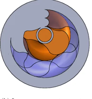
[image:3.595.343.493.382.550.2](b) Internal screw machine model
Figure 2: Rotor profiles and CAD model of internally geared screw machine with Ni = 2,
ρe/E = 0.5, L/2ρo,max = 1.55 and φo,w = 300◦. The internal rotor is shown in orange, the
external rotor is transparent, and the stationary end plates are illustrated
This helical internally geared rotor configuration has a number of potential advantages compared to a conventional screw machine:
• Elimination of rotor-to-casing tip clearances present in conventional screw machines, as the outer rotor encloses the working chamber. The two rotors of the internally geared machine effectively share the same tip leakage areas.
• Elimination of the blow hole area characteristic of conventional machines, and a resulting reduction of the interlobe sealing line length.
(a) High pressure port geometry (b) Low pressure port geometry
Figure 3: Details of the port shapes for the high and low pressure end plates designed to achieve v = 4.5 for the rotors shown in Figure 2
• Reduced viscous drag due to the much lower relative speed at the contact lines between rotors, as compared to the rotor-casing leakage lines in a conventional machine.
• Reduced distortion due to thermal expansion, as the rotation of both rotors will lead to a uniform circumferential temperature in each during operation, with temperature variation limited to the axial direction.
2. Geometry of simple rotor profiles for internally geared machines
Internally geared positive displacement machines require continuous contact points between inner and outer rotors during rotation about parallel axes. This allows the formation of enclosed working chambers whose volume varies with the angular position of the rotors. A wide range of rotor profiles can be generated that meet this requirement. In this paper, simple geometries consisting of epicycloids and hypocycloids are used to illustrate this requirement of continuous contact between rotors and to investigate machine performance. This requires that the inner rotor has one fewer lobe than the outer rotor. The equations defining coordinates of epicycloid and hypocycloid profiles are shown in Equations 1 and 2. While cycloids are used in this paper to illustrate the analysis of internally geared machines, it should be noted that there is considerable scope for optimisation using other methods of rotor profile generation.
xe(θ)
ye(θ)
=
(ρb+ρe)cos(θ)−ρecos(θ(ρb/ρe+ 1))
(ρb+ρe)sin(θ)−ρesin(θ(ρb/ρe+ 1))
(1)
xh(θ)
yh(θ)
=
(ρb−ρh)cos(θ) +ρhcos(θ(ρb/ρh−1))
(ρb−ρh)sin(θ)−ρhsin(θ(ρb/ρh−1))
(2)
Continuous contact between rotors can be achieved using composite profiles which can be created by combining sections of epicycloid and hypocycloid profiles. The profiles are defined by the radius of the base circle,ρb, the number of lobes required on the rotor,N, and the radius of the
epicycloid generating circle,ρe, where 0≤ρe≤ρb/N. By considering the circumferences of the
epicycloid and hypocycloid generating circles, it can be seen that the radius of the hypocycloid generating circle is:
The maximum and minimum radii of the rotor are as follows:
ρmax =ρb+ 2ρe, ρmin =ρb−2ρh =ρb(1−2/N)−2ρe (4)
It is clear that whenρe= 0 orρh = 0, the rotor is a pure hypocycloid or epicycloid respectively.
In order to achieve the required meshing condition between the inner and outer rotors the following conditions are required:
ρb,o/No=ρb,i/Ni, ρe,o=ρe,i, No=Ni+ 1 (5)
The offset distance between the axes, E, can then be defined as follows:
E =ρmax,i−ρmin,o=ρb,i+ 2ρe,i−ρb,o(1−2/No)−2ρe,o (6)
Rearranging Equation 6 and substituting for the relationships in Equation 5 results in the following expression:
ρe,o/E =ρe,o/(ρe,o+ρh,o) (7)
It is clear from Equation 7 that the possible values of the ratio ρe,o/E range between zero
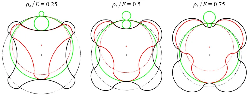
and one, corresponding to the cases when the rotors are pure hypocycloids and epicycloids respectively. In all the examples presented in this paper, the geometric parameters for the outer rotor have been chosen in order to achieve a maximum profile radius of 0.5 m, and the profile is therefore bounded by a circle of diameter 1 m. Hence the results can be scaled to find the geometric characteristics of any specified rotor size. As seen in Figure 4, the inner rotor must be scaled such that ρo,min = (ρi,min+E) in order to allow the rotors to mesh and achieve the
required continuous contact. The meshing condition requires that the normal to both rotor profiles must pass through the pitch point of the rotors, and is used to identify the location of the contact points for a given angular position of the rotors. The locii of these contact points during rotation can therefore be found. These are shown in Figure 4, along with the pitch circles of the rotors which are shown to be the same as the base circles used to generate the epicycloid and hypocycloid curves. Note that all profiles are shown with the angular position of the outer rotor,φo= 0, which has been chosen as the position where rotor contact occurs at the minimum
radius of both rotors.
[image:5.595.92.505.541.699.2]E = 0.25 E = 0.5 E = 0.75
Figure 4: Inner (red) and outer (black) rotor profiles for values of ρe,o/E = 0.25,0.5 and 0.75,
3. Geometric properties
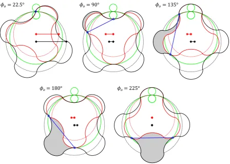
When considering the 2-dimensional rotor profiles generated in Section 2, it is possible to identify the angular position of the rotors at which two contact points coincide. Rotation relative to this point creates an area between the two contact points, bounded by sections of the inner and outer rotor profiles. This is illustrated for various rotor positions in Figure 5. For a given rotor position, the area of working chamber is shown in grey, while the leading and trailing contact points are shown as circular blue markers. The line connecting these represents the projected area per unit rotor length over which the pressure acts on the rotors. The perpendicular distance between the line of action of the net force and the axes of rotation are shown on the x-axis relative to each rotor centre. The calculated working chamber area is shown in Figure 6 as a function of the outer rotor position for the three rotor profiles shown in Figure 4.
= 22.5° = 90° = 135°
[image:6.595.74.523.266.587.2]= 180° =225°
Figure 5: Geometry of rotors with Ni = 3 and ρe/E = 0.5, showing working chamber area,
contact points, projected area for pressure force and perpendicular distance between the line of action and the rotor centres
The sliding velocity is defined as the velocity of the outer rotor relative to the inner rotor at the contact point, and is also a function of the rotor geometry. For the particular geometry shown in Figure 5, the sliding velocity of the leading and trailing contact points of the highlighted working chamber are given in Figure 7a. The maximum sliding velocity is also shown in Figure 7b for profiles with Ni = 3 and 0≤ρe/E≤1.
0 90 180 270 360 450 0
0.05 0.10 0.15
Angular position of outer rotor (deg)
Area of working chamber (m
2 )
[image:7.595.197.399.112.260.2]0.25 0.5 0.75 E
Figure 6: Cross sectional area of working chamber as a function of the angular position of the outer rotor, φo, for the profiles shown in Figure 4
(m) L ea ding con ta
ct p o int Tra ilin g c
onta ct p
oint
0.3
0.2
0.1
0
0 90 180 270 360 450
Angular position of outer rotor (deg)
Sliding veloci
ty
per unit
(a) Normalised sliding velocity as a function of the angular position of the outer rotor for the profile shown in Figure 5
0.2 0.4 0.6 0.8 1
0 0.25 0.24 0.23 0.22 E Normalised epicycloid generating radius,
Max slidi
ng vel. per unit (m)
[image:7.595.79.286.309.466.2](b) Maximum normalised sliding velocity as a function of the normalised epicycloid generating radius,ρe/E, whenNi= 3
Figure 7: Sliding velocity of rotor contact points normalised by angular velocity of the outer rotor, ωo
given rotor position. As for conventional screw machines, this requires the wrap angle of the rotors to be defined along with the length [6]. Using the values specified in Table 1 and the profiles shown in Figure 4, the volume of the working chambers has been calculated as shown in Figure 8a. This allows the swept volume per revolution of the machine to be calculated for a range of profiles and rotor lobe numbers, as shown in Figure 8b.
Table 1: Characteristics of internal screw geometry.
Parameter Value
Outer rotor length-diameter ratio,L/2ρo,max 1.55
Outer rotor wrap angle,φo,w 300◦
[image:7.595.314.511.312.463.2]0 180 360 540 720 0
0.02 0.04 0.06 0.08
0.10 0.12
Angular position of outer rotor (deg)
V
olume of working chamber (m
3 )
0.25 0.5 0.75 E
(a) Volume of a single working chamber as a function of the angular position of the outer rotor for the profiles shown in Figure 4
E Normalised epicycloid generating radius,
V
olume per rev of inner rotor (
m
3 /rev)
0 0.2 0.4 0.6 0.8 1
0.24 0.26 0.28 0.30 0.32
Ni = 5 Ni = 4 Ni = 3 Ni = 2
(b) Swept volume per revolution of inner rotor as a function of ρe/E for rotors with Ni = 2,3,4
[image:8.595.306.519.111.274.2]and 5. Circular markers indicate the three cases illustrated in Figures 4
Figure 8: Volume of working chamber and machine
v, defined as the ratio of the maximum-to-minimum volumes of the working chamber that occur
while it is closed off from both ports. The angular position of the rotors at which the ports open and close can therefore be defined once the working chamber volume is characterised. A 3D model of an internally geared screw machine with stationary end plates to allow compression or expansion of the working fluid is shown in Figure 2. The rotor position shown is such that a working chamber is slightly open to the high pressure port; in a compressor this corresponds to the early stages of discharge of high pressure gas, or the final stages of suction for an expander. The shape of the ports in the high and low pressure end plates is shown in more detail in Figure 3. The shape of the ports is defined by the shape of the rotor profiles and the locii of the contact points. Defining the ports as shown in Figure 3 eliminates any open paths between an enclosed working chamber and the high and low pressure ports until required for suction or discharge. In reality the necessary clearance gap between the stationary end plates and the rotors will results in end face leakage, as in a conventional screw machine.
4. Operational characteristics
An important factor to consider in selecting rotor profiles is the torque generated on both rotors by the pressure variation in the working chamber during a compression or expansion process. In order to minimise the contact forces that occur between the rotors, the net torque exerted on the non-driven rotor by the working fluid should be minimised. This ensures that power is transferred directly from the driven rotor to the working fluid, with minimal power transferred between the rotors. From the 2D analysis described in Section 3 we can consider a thin slice of the rotor and find the projected area and direction of the pressure force created by the working fluid on the two rotors. The direction of the force allows the torque exerted on the two rotors to be calculated. By integrating these forces and torques along the axial length of the working chamber, the instantaneous torque, axial force and radial force can be calculated for a given rotor position [6]. The net torques and forces generated during a complete cycle can then be found, and the net effect of all working chambers can be considered.
4.1. Analysis of rotor torque for compressor application
[image:8.595.72.279.120.277.2]• Working fluid is an ideal gas (γ = 1.4)
• Isentropic compression/expansion process
• Discharge pressure equal to working chamber pressure after compression/expansion
• No pressure drop occurs during filling and discharge of working chamber
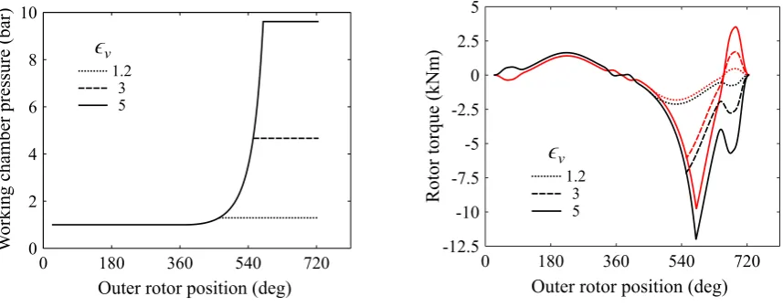
• No leakage between inner and outer rotors or between end plates and rotor end faces An example of the results from this initial analysis of the internally geared screw machine are presented below. The pressure variation in a single working chamber and the resulting rotor torque variation with rotor position are shown in Figure 9, while the net effect of all working chambers on the rotor torque is shown in Figure 10.
0 180 360 540 720
0 2 4 6 8 10
Outer rotor position (deg)
W
orking chamber pr
essure (bar) 3
1.2
5
ϵ
v(a) Working chamber pressure
0 180 360 540 720
-12.5 -10 -7.5 -5 -2.5 0 2.5 5
Outer rotor position (deg)
Rotor torque (kN
m)
3 1.2
5
ϵ
v [image:9.595.85.514.263.431.2](b) Rotor torques for single working chamber
Figure 9: Working chamber pressure and corresponding rotor torques as a function of rotor position for internally geared screw compressor with ρe/E = 0.5 andpsuc= 1 bar, for the three
cases whenv = 1.2, 3 and 5 (note that in (b) red and black lines correspond to inner and outer
rotor respectively)
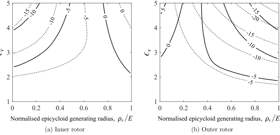
The maximum and minimum net torque exerted on each rotor during operation can therefore be found as a function of v and the rotor profiles. This has been calculated for a range of
conditions with 1 ≤v ≤5 and 0 ≤ρe/E ≤1, and the resulting maximum and minimum net
torque for each rotor are shown as contour plots in Figure 11. These contour plots allow a rotor profile to be selected in order to minimise the net torque on the undriven rotor, and thereby limit the force occurring at the contact points during operation. This is illustrated in Figure 12, which shows the rotor torques that occur when using the limiting values of ρe/E that achieve
an instantaneous net torque of zero on the undriven rotor at some point during operation.
5. Conclusions
The main conclusions from the current study are as follows:
• Constant profile and pitch internally geared screw machines can achieve compression or expansion via the use of stationary ported end plates.
• Helical rotors with simple composite epicycloid-hypocycloid profiles can achieve the required continuous meshing condition.
0 60 120 180 240 300 360 -3
-2 -1 0 1 2
Outer rotor position (deg)
Net rotor torque (kNm
)
(a) Net torque whenv= 1.2
0 60 120 180 240 300 360
-20 -15 -10 -5 0 5
Outer rotor position (deg)
Net rotor torque (kNm
)
[image:10.595.79.517.110.300.2](b) Net torque whenv= 5
Figure 10: Torque from all working chambers (dashed lines) and resulting net torque on inner and outer rotors (solid lines) as a function of outer rotor position for internally geared screw compressor withρe/E = 0.5,psuc= 1 bar and the specified values ofv
0 0.2 0.4 0.6 0.8 1
1 2 3 4 5
-10 -5 0
-15
-10
-5 0
E Normalised epicycloid generating radius,
v
(a) Inner rotor
0 0.2 0.4 0.6 0.8 1
1 2 3 4 5
E Normalised epicycloid generating radius,
-15
-10
-5 0
5
-20
-15
-10
-5
v
(b) Outer rotor
Figure 11: Maximum (solid lines) and minimum (dashed lines) net torque (kNm) on inner and outer rotors as a function of ρe/E and v for the compressor (note: Ni = 3, psuc = 1 bar and
pdis=pwc,max as shown in Figure 9)
• The rotor profile and choice of driven rotor can be selected to minimise torque on the undriven rotor.
• For the simple composite cycloid profiles with Ni = 3 and for the operating conditions
considered, the ratio of undriven-to-driven rotor torques is minimised when ρe/E is in the
range 0.76−0.9, in which case the outer rotor should be driven.
• If the inner rotor is driven the maximum undriven-to-driven torque ratio is significantly higher, leading to higher contact forces between the rotors.
[image:10.595.76.524.360.576.2]0 60 120 180 240 300 360 Outer rotor position (deg)
-20 -15 -10 -5 0 5 10
Net rotor torque (kNm
)
(a)ρe/E= 0−0.19
0 60 120 180 240 300 360
Outer rotor position (deg) -30
-20 -10 0 10
Net rotor torque (kNm
)
[image:11.595.88.513.110.290.2](b)ρe/E= 0.76−0.90
Figure 12: Range of values of ρe/E that achieve a net torque of zero on a) the outer rotor and
b) the inner rotor during a compression cycle when Ni = 3,psuc= 1 bar and v = 5
geared configuration with conventional screw machines. This will be achieved via:
• Calculation of axial and radial bearing loads.
• Characterisation of sealing line lengths and leakage flows.
• Characterisation of port areas as a function of working chamber volume.
• Investigation of other internally geared rotor profiles that achieve the required condition of continuous contact.
Nomenclature
E Distance between rotor axes (m) ρ Radius (m)
L Rotor length (m) θ Cycloid generating angle (rad)
N Number of lobes on rotor φw Wrap angle of rotor (deg)
p Pressure (bar) v Built-in volume ratio
φ Rotor angular position (deg)
References
[1] Colbourne, J.R., 1974. The geometry of trochoid envelopes and their application in rotary pumps. Mechanism and Machine Theory, 9(3-4), pp.421-435.
[2] Beard, J.E., 1985. Kinematic analysis of gerotor type pumps, engines, and compressors, PhD thesis.
[3] Beard, J.E., Yannitell, D.W. and Pennock, G.R., 1992. The effects of the generating pin size and placement on the curvature and displacement of epitrochoidal gerotors. Mechanism and Machine Theory, 27(4), pp.373-389.
[4] Vecchiato, D., Demenego, A., Argyris, J. and Litvin, F.L., 2001. Geometry of a cycloidal pump. Computer methods in applied mechanics and engineering, 190(18), pp.2309-2330.
[5] Litvin, F.L. and Fuentes, A., 2004. Gear geometry and applied theory. Cambridge University Press.
![Figure 1: Illustration of a conventional Gerotor type internally geared pump [4]](https://thumb-us.123doks.com/thumbv2/123dok_us/1427331.95378/3.595.209.384.107.271/figure-illustration-conventional-gerotor-type-internally-geared-pump.webp)