Analytical Study on Behavior of Structures with
and without Infill Panel using ANSYS
Bhagya Raj Jowdula1, K.Niveditha2, P. Dilip Kumar Rao3, J. John Samuel4, B.Akhila5
1
PG Student(Structural Engg.) Siddhartha Institute of Technology and Sciences, Narapally Hyderabad,
2
Assistant Professor(HOD) SITS ,
3
Assistant Professor SITS,
4
Assistant Engineer (Environmental) PH&ME A.P,
5
Assistant Professor VSIT
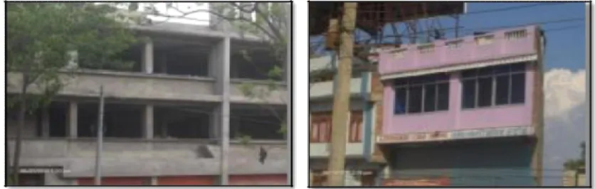
Abstract: In Reinforced concrete frames, a common practice is to provide masonry infill walls. Infill panels are widely used as partition walls as well as external walls of the building to fill the gap between RC frames. Masonry infill typically consists of bricks or concrete blocks constructed between beams and columns of a reinforced concrete frame. Infill walls are considered as non-structural member who provide considerable stiffness to the building and hence may improve the performance of the RC building during ground motions. In most of the cases, the ignorance of this property of masonry, in designing of the RC frames to resist lateral loads results in unsafe design. The IS code does not provide guidelines for the analysis and design of RC frames with infill wall. So it is essential to consider the effect of masonry infill for the seismic evaluation of moment resisting reinforced concrete frame. The infill’s play significant role in enhancing the lateral stiffness of complete structure. The behaviour of RC frame building subjected to different load-cases has been carried out by considering with and without the infill wall. The purpose of this analysis is to study the behaviour of RC structure especially when it is subjected to seismic loads.
A 3-bay and 3-storey frame is used for analysis in software package ANSYS. ANSYS is a general purpose finite element modelling package for numerically solving a wide variety of problems which include static/dynamic structural analysis (both linear and nonlinear), heat transfer and fluid problems, as well as acoustic and electro-magnetic problems. Static non-linear analysis is used to analyze the model. For modelling the structure certain pre-investigation properties are required which are to be found out by laboratory testing. The output requirements such as Deflection diagrams and cracking diagrams (Failure modes) are obtained when RC frame is subjected to different load-cases. The results obtained are compared for RC frame with infill and RC frame without infill. In the present study, the deflections are highest in structure without infill. It is also seen that Cracks start forming at a load of 15KN-20KN for frame without infill whereas for frame with infill it is 20KN-25KN. Further, it is observed that the structure with infill can take 25% to 40% more loads as compared to structure without infill.
Keywords: Masonry infill, lateral stiffness, cracks, deflection, loads, ansys
I. INTRODUCTION
In the past, the buildings were designed only for occurrence of calamities are on rise resulting in recent times, huge losses caused to both property and life, the governmental agencies have been revising the structural design codes frequently to withstand all kinds of calamities.
To counter the effect of lateral forces, the shear walls are provided in building structures. The specifications for shear walls have already been developed in the design codes. But the large sized shear walls provided in buildings always become an obstacle for vehicle movement in the parking lots. This apart, the other functional utilities of the building are also partly affected due to the presence of shear walls emanating from basement floor to the topmost floor. In this backdrop, the infill contribution to resist lateral loads has come in very handy and the investigation is progressing in this direction.
A. Classification based on degree of presence of infill:
Infill’s are provided fully or with openings as per the needs for provisions of partitions or for doors and windows. The four different general types of frames are:
1) Bare frame 2) Fully infilled frame
4) Partial infilled frame
Fig. 1 Partially infilled frames
B. Need for Present study
At present, brick masonry is most commonly used in framed buildings to cover the area within the frames or act as partition walls. It is generally not considered to contribute any strength to the structure. Hence, the common practice has been to ignore the infill during the analysis and design of frame structures. However, infill wall tends to interact with the surrounding frame when the structure is subjected to lateral loads. Thus, the frame-infill interaction cannot be ignored since under a lateral load, infill wall contributes to the overall strength and stiffness of the structure.
As on date, there are no provisions in the code infill frame since there are no rational methods to determine the strength of infill. Unlike concrete, the properties of brick masonry used for the infill wall panel and the cement mortar used as link element are not generalized. Also, the strength of infill depends on workmanship and quality of the brick used. Hence the analytical study is needed.
C. Objectives of the Present Study
1) To determine crack pattern of infill panels subjected to incremental oads. 2) To determine the deflection of frame for different load-cases.
3) To do the comparative study of crack patterns obtained for frame with infill panel and frame without infill. 4) To do the comparative study of deflections obtained for frame with infill panel and frame without infill.
D. Scope of the present study
The scope of present study involves work in various stages. In the initial stage experimental investigation for materials (cement, aggregate, steel, bricks) are carried out. These inputs are then imported for further analytical work. The modeling of frame with accurate dimensions is done in ANSYS software. The analysis part is carried for the frame. The behavior of frame for horizontal as well as vertical load cases is observed. Also the behavior of frames for different load cases applied at different beam-column junctions is observed. Finally the crack pattern and deflection for frames with infill and frames without infill are compared and conclusion is drawn.
II. METHODOLOGY
The methodology of my current work includes, all dimensions of on-field model are measured and drawn with accurate dimensions in AUTOCAD software. The AUTOCAD drawing is useful to model the frame in ANSYS easily. The frame is subsequently modeled in ANSYS software and Pre-processing operations are done. The required outputs such as Deflection and Crack pattern are then calculated and compared for different cases.
Field model has 3 spans in both horizontal and vertical directions. Both the beam and columns are made with M20 grade concrete. All the ends of the frame are fixed to the loading frame. Following are the materials required:
Fe415 steel of dia12mmSteel Loading frame of size 3m x 2.385m Steel plates of thickness 16mm
A. Analytical Model Using ANSYS:
The finite element method is a numerical analysis technique for obtaining approximate solutions to a wide variety of engineering problems. ANSYS is a general purpose finite element modeling package for numerically solving a wide variety of problems which include static/dynamic structural analysis (both linear and nonlinear), heat transfer and fluid problems, as well as acoustic and electro-magnetic problems. The 3.0m x 2.385m RC frame with reinforcement have been analyzed using a finite element (FE) model in ANSYS. Here, a nonlinear analysis is considered throughout the study by assuming that there is a perfect bonding between concrete and steel reinforcement. In the present study following cases are analyzed for frame with infill and frame without infill: 1) Bare frame subjected to horizontal point loads at all beams column junctions.
2) Bare frame subjected to vertical point loads at all beams column junctions. 3) Infill frame subjected to horizontal point loads at all beams column junctions. 4) Infill frame subjected to vertical point loads at all beams column junctions.
III. ANALYTICAL PROGRAMME
A. Analytical Experiment using ANSYS R17.0:
ANSYS 17.0 makes the analysis of structures easy. Using ANSYS 17.0 the frame structure is modeled first with the practical dimensions of 3000 mm x 2385 mm frame size and beams & columns of cross sectional dimensions 100 mm x 100 mm. All the ends of the beams and columns are assigned fixed support conditions. The following are the main stages in analysing the frame. Assigning material properties
Modeling Meshing
Assigning support conditions Assigning loads at required point Solving the frame
Plotting results
1) Preferences:The preferences window shows various options like structural, thermal, ANSYS fluid, out of which ―Structuralǁ is
to be checked in box.
2) Pre-processor: Preprocessor tab is the one which takes all the inputs required to solve a given structure in ANSYS. The pre-processor tab is helpful before to design the structure and insert various inputs required. It includes various options like element type, material properties, sections, modelling, meshing,
3) Element type:Element type tab gives various options to be selected for the structure like Link, beam, pipe, solid, shell, ANSYS fluid, electrostatic, circuit, thermal electric, pore pressure, super element, surface effect etc. in our present work SOLID 65 is used as shown in figure 4.4. The solid65 element is capable of cracking in tension and crushing in compression. The multi linear isotropic concrete model uses the von Misses failure criterion along with William and Warnke model to define the failure of concrete. If other materials are used, then further other element type can be chosen depending upon the material used.
4) Modelling:The solid65 element models the nonlinear response of reinforced concrete. The behavior of the concrete material is based on a constitutive model for the triaxial behavior of concrete after Williams and Warnke. Solid 65 is capable of plastic deformation, cracking in three orthogonal directions at each integration point. The cracking is modeled through an adjustment of the material properties that is done by changing the element stiffness matrices. If the concrete at an integration point fails in uniaxial, biaxial, or triaxial compression, the concrete is assumed crushed at that point. Crushing is defined as the complete deterioration of the structural integrity of the concrete.
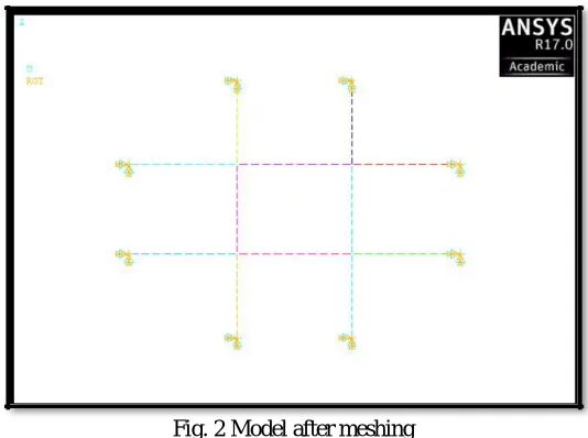
5) Meshing:Meshing is very important stage after modelling. If meshing is not properly done total results may go wrong. To obtain the satisfactory results from the solid 65 element a Hex-mapped meshing was chosen. Firstly the line division is done based on the required nodal criteria. Later volume meshing is created.
Fig. 2 Model after meshing
Then vertical load is applied at the same point starting from 5KN and increasing gradually. This process is repeated for each node and the results are obtained.
7) Solution: The preprocessing work gives necessary inputs of material properties, modelling, boundary conditions and loading at required locations. The next step is to solve the structure for the given conditions. This function solves the given pre-processor elements. Select solution tab and then go to ―solveǁ tab, and then go to ―Current LSǁ
IV. RESULTS AND DISCUSSIONS
After modelling the structure in ANSYS R17.0 different results of deflection and cracking for loading beginning from 5KN to 40KN are tabulated. The trend for deflection and cracking are observed for the following cases:
A. StructurewithoutInfill
[image:5.612.191.458.85.284.2]1) Cracking:The cracking location of the structure can be found by increasing the load from 5KN to 40KN. Red-spots in the diagram shown indicates the origin of cracks. Cracks will propagate with increase in load. Thus, the cracking propagation needs to be observed.
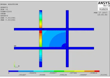
2) Deflection:After knowing the cracking load and its propagation the deflection pattern can also be observed. We can observe the positions of maximum deflection value and minimum deflection value in the structure. In the figures the maximum deflection is indicated with red colour whereas the minimum deflection value is indicated with blue colour. Also the position of maximum
[image:6.612.123.487.138.349.2]deflection is indicated with letters ―MXǁ and the minimum deflection position is indicated with ―MNǁ.
Fig. 4 Deflection diagram for application of horizontal load of 25KN at point-1
3) StructurewithInfill
Fig. 5 Deflection diagram for application of horizontal load of 20KN at point-1
[image:6.612.132.501.393.655.2]V. CONCLUSION
A. Based on the analytical work carried out in the present investigation the following conclusions can be drawn:
1) For frame without infill, for a load of 5KN the deflection varies from 0.118649mm to 0.15635mm whereas for frame with infill the deflection varies from 0.00083mm to 0.001883mm.
2) For frame without infill, for a load of 10KN the deflection varies from 0.237298mm to 0.312699mm whereas for frame with infill the deflection varies from 0.000851mm to 0.003366mm.
3) For frame without infill, for a load of 15KN the deflection varies from 0.355947mm to 0.469049mm whereas for frame with infill the deflection varies from 0.000872mm to 0.009062mm.
4) For frame without infill, for a load of 20KN the deflection varies from 0.474459mm to 0.625399mm whereas for frame with infill the deflection varies from 0.001264mm to 0.017261mm.
5) For frame without infill, for a load of 25KN the deflection varies from 0.593245mm to 0.781748mm whereas for frame with infill the deflection varies from 0.003612mm to 0.022778mm.
6) For frame without infill, the max deflection for all cases occurs near the point of application of load.
7) For frame without infill, the cracking starts at a load of 15KN-20KN on an average whereas for frame with brick infilll, the cracking starts at a load of 20KN-25KN on an average.
8) Brick with infill wall panel can take 25% to 40% more loads compared to brick without infill wall panel.
9) For frame without brick infill panel with horizontal loading, the maximum deflection occurs near point of application of load whereas for frame with brick infill, the maximum deflection occurs inside infill wall panel.
10) For frame without brick infill panel with vertical loading, the maximum deflection occurs along the beam near point of application of load whereas for frame with brick infill, the maximum deflection occurs near the point of application of load inside infill wall panel.As per strength point of view, brick with infill wall panel is preferred over brick without infill wall panel as it can take more loads comparatively.
VI. FUTURESCOPE
The present study may be regarded as a preliminary work for an extensive research work on the effect of various parameters on infilled frames due to lateral loading. The recommendations are:
A. The present can be extended for different aspect ratio of the model.
B. Present work can be done in MSC NASTRAN and other Analytical software apart from ANSYS R17.0 software with openings. C. Instead of solid brick infill other types of infill such as concrete block can also be used and also composite materials can be
used for such type of investigation.
VII. ACKNOWLEDGMENT
My sincere thanks for my college staff members .My heartfelt gratitude towards my family members and friends for supporting me during this research work.
REFERENCES
[1] Akash D. Mundawareet. al. (2016) ―Seismic behavior of RC frame building and its analysis with improving measuresǁ, International Journal of Advance
Research and Innovation, 4(2): 1-11.
[2] Narendra A. Kapleet. al. (2016) ―Seismic Analysis of RC Frame Structure with and Without Masonry Infill Wallsǁ, International Conference on Electrical,
Electronics, and Optimization Techniques (ICEEOT) – 2016, 101-106