Fault Tolerant Protocol for UDS Flash
Programming through Controller Area Network
(CAN)
Divya.J1, Shanthi.T2 1
PG Scholar, 2Assistant Professor, Department of EEE 1,2
Kumaraguru College of Technology, Coimbatore, India
Abstract— This paper proposes a fault tolerant protocol for CAN (Control Area Network) flash programming. Recently, the need of CAN flash programming is rapidly increasing because the number of installed ECU (Electronic Control Unit) increases noticeably and the adoption rate of CAN are very high. Although some development tool companies and semiconductor companies provide solutions for Flash Programming in a effective way, there is no standards for CAN flash programming until now. Furthermore, there is always a risk of nature , when Flash programming an application into flash memory using downloaded programming algorithms, that an externally created aspects may corrupt the programming process. This paper gives a brief suggestions that the standards of CAN flash programming should include mechanism for the recovery from faults and certification process. Interaction diagram between host PC and ECU summarizes the messages and includes an additional phase for the certification of the CAN communication capability of ECU. The Reprogramming operation is done through Diagnostic communication protocol UDS. For a Diagnostic Communication a testing tool is connected to the in-vehicle network. The Tester (Client) sends a request to a Specific ECU and the ECU (Server) answers the request with a response. Here, Simulated ECU comes in play by sending responses to the request.
Keywords— CAN, Flash programming, Fault tolerant, Protocol, UDS.
I. INTRODUCTION
As the mechanical components in automotives are replaced With electronic implementations, automobile sectors deals with more And more ECUs (Electronic Control Unit). Furthermore, almost every ECU adopts CAN (Control Area Network) to Share the information of sensors and controllers. According to the popularization of CAN-installed ECU, the needs of calibration and diagnostics using CAN are increasing rapidly. The interaction layer for the purpose of diagnostics, which supports continuous data transfer. Established KWP 2000 on Kline tends to be replaced with KWP 2000 on CAN, which then replaced by UDS on CAN .UDS(Unified Diagnostics Protocol) defines the protocol of calibration and Diagnostics using CAN communication. After the calibration and diagnostics with CAN takes root successfully, it is known that CAN will improve the maintenance of ECU software. If ECU software can be updated by widely spread CAN, automobile makers can update ECU software ordinarily in cooperation with service network and can avoid expensive recall eventually. Recently, protocols for the software update with CAN are published by several development tool companies and semiconductor companies. However, they are not standardized like the calibration and diagnostics with CAN through UDS until now and they are a kind of implementation based on the primitive functions. For the implementation of CAN flash programming, robust treatment of faults during programming process is as important as the establishment of global standards. Because ECU adopting CAN flash programming generally does not have a special hardware for the flash programming and mode selection, ECU can become dead by the failure during programming process if it does not have any solution for the recovery from faults. In spite of the seriousness of the faults during CAN flash programming, published solutions assume that the programming process will not be disturbed and terminates properly.
At first, this paper enumerates potential disturbances during flash programming. In spite of the various causes of disturbances, malfunctions with respect to CAN flash programming can be summarized into two categories 1) incomplete application, 2) application incapable of CAN Communication. Incomplete application can be caused by power down of ECU, communication line disconnection, insane CAN node and shut down of host PC during CAN flash programming. Incapability of CAN communication of ECU after CAN flash programming can be caused by the incorrect setting of CAN driver, the incorrect setting of transportation layer of CCP and the incorrect setting of task
calibrate an ECU’s control and diagnostic parameters depends on reliable access to the ECU.
We need the following components to Flash ECUs:
A. Flash file
File data to be ported to the ECU’s flash memory.
B. Flash tool
Flashes the contents of the flash file on to the ECU.
C. Flash job (flash sequence)
Sequence of diagnostic functions for reprogramming the flash memory in the ECU.
Proposed protocol specifies that ECU can be reprogrammed via CAN without the risk of being dead node.
II. FAULT ANALYSIS AND REQUIREMENTS
The fault analysis result of potential disturbances which may occur during programming flash memory through CAN. In spite of various causes of disturbances, malfunctions with respect to CAN flash programming can be summarized into two categories: “incomplete program” and “application incapable of CAN communication”.
Flash programming process consists of four phases: handshaking, erasing, programming and verification. Faults occurring before the erasing phase do not affect the recoverable capability of ECU. Although faults between the erasing phase and the programming phase are various, they are summarized into one category named “incomplete program” because the existing program is destroyed and the new program is incomplete. In the verification phase, process discontinuance itself does not mean the deficiency of recoverable capability the discontinuance of verification phase without another defect does not affect the recoverable capability of ECU. If the CAN driver setting of new program such as CAN ID and communication speed is incorrect, ECU is unable to use communication through CAN. If there is a defect of the setting of OSEK COM interaction layer, CCP transaction layer and communication, transfer of data is Aborted and flash programming fails in spite of the correct operation of CAN communication.
New requirement of CAN flash programming protocol, which reflects the result of fault analysis and refers to the existing implementation, is listed in the below.
A. Existing flash Reprogramming through K-line uses a Specific message during the power-on period or uses hardware switch as the indicator of booting mode. Because CAN has multiple connected nodes, specific message during the power-on period cannot be used. Furthermore, attaching hardware switch to every ECU is too expensive and Impractical. Therefore, flash programming must be able to be initiated by CAN message during normal mode without any additional hardware.
B. Current usage of flash memory generally occurs by Using block-wise access control ; While erasing information in a certain block, reading information in the block is impossible. Therefore, the program implementing downloading should reside in RAM area.
C. To obtain the independence of operation context and the maintenance of the operation, it is preferred to develop the CAN flash programming as three independent programs : application program, booting program and downloading
program.
III.DIAGONISTIC PROTOCOL
Protocols have always been standardized whenever different test systems (e.g. in brand and independent repair shops) are to access vehicles or different ECUs have to be integrated into subsystems – requirements that are in fact always demanded nowadays. There are two types of communication. Onboard type of communication and Diagnostic type of communication between Tester application and ECU’s
A. Onboard Communication
1) ECU’s coverts input information from sensors to output information for actuators.
3) For onboard communication ECUs are interconnected via an in-vehicle communication network(e.g.: Controller Area Network)
Fig: 1Onboard Communication
B. Diagnostic Communication
1) For a Diagnostic Communication a tester is connected to the in-vehicle network.
2) The Tester (Client) sends a request to a Specific ECU (e.g. : #1), and the ECU (Server) answers the request with a response
Fig:2 Diagnostic Communication
C. Diagnostic Service
Diagnostic communication requires Diagnostic Protocol A diagnostic protocol contains a set of communication parameters and diagnostic services (request and responses).
UDS (Unified Diagnostic Service) is based on the standards KWP2000 and CAN. It was created with the goal of standardizing different implementations of the predecessor standards and new requirements stemming from further developments in technology and new standards to form one generally valid diagnostic protocol. UDS describes the layer 7 protocol (diagnostic services) but is based on an extended version of the diagnostic protocol of KWP2000 on CAN (ISO 15765-2). UDS specifies data link independent requirements of automotive diagnostic services in road vehicles. UDS is given as a standard in ISO 14229-1:2013 and allows diagnostics to control functions on an in-vehicle Electronic Control Unit (ECU).
D. Security
UDS services may have a security mechanism applied, whereas predefined services may not. These Services with a security mechanism are designed with the appropriate security level name in the column where the security applies. UDS defines various levels of security leading to 33 security levels for general use and there is no assumed relationship between levels.
The UDS protocol gives a various number of necessary functionalities for developers and testers so that they can perform,
1) read or write data in ECU memory,
2) program the flash memory
3) Create specific behavior for an ECU.
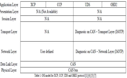
CAN buses. A CAN frame contains a data field and a CAN ID field.
[image:5.612.206.420.135.267.2]The values of these fields are determined by higher layer protocol such as UDS, Universal Calibration Protocol (XCP), CAN Calibration Protocol (CCP) and On-Board Diagnostics II (OBD2), which have a variety of frame formats. The OSI layer must be classified first for an efficient implementation
Fig 3 OSI Model for UDS Protocol
E. Message Structure
The message structure of the UDS services consistent with the structure of OBD: The first byte is the Service ID. Then the functionality of the service follows the so-called sub-level identifiers.
At UDS, there is the possibility to give positive response or Negative response to Request messages. If the Service request ID success and all criteria being matched Positive response will be provided by the ECU or Simulated ECU. On the other hand if any of the criteria is being not matched Negative response has to be sent to the diagnostic tester application. Negative responses in the absence of positive response messages are useful.
IV. SEQUENCE DIAGRAM OF PROTOCOL
B. State Diagram Of Protocol
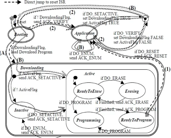
[image:6.612.192.466.424.645.2]Designing the state diagram of ECU state, which is Controlled by the CAN messages defined in the sequence Diagram, makes the transitions. Figure 4 shows the state diagram of proposed protocol. Circle and rounded rectangle represents a state. Double line represents the boundary of a program. Arrow represents a state transition and dotted arrow represents a context switching by direct jump to reset ISR (Interrupt Service Routine). It is assumed that three programs have their own ISRs. Dark circle(•) represents the starting point of the certain level of a hierarchical state diagram. Bull’s eye( ) represents the ending point of the certain level of a hierarchical state diagram. Developed state diagram has only one ending point at the highest level, which depicts the reset forced by the application program. In this case, hardware reset will occurs as the gray arrow depicts. Downloading Flag and Active Flag is the variable reflecting the current ECU state and they are located in treated as TRUE for the Downloading Flag, but FALSE For the Active Flag. Such interpretation of state variable sets the initial state of ECU to Downloading-Inactive State. Erasing operation is implemented by two states: Ready To Erase and Erasing, to guarantee the parallel operation during the execution of erasing command. Such kind of implementation is needed because a general flash memory is asynchronous, in other words, the return from an instruction does not mean the completion of the instruction. Because of the same reason, the programming operation is implemented by two states : Ready To Program and Programming. In general, the periodic triggering of finite state machine guarantees the parallel operation by multi-thread, which is an important advantage over an infinite polling loop. Especially, lossless CAN communication needs the implementation suitable for the parallel operation. Path (A) and (B) in Figure 4 show the state transition sequence of the handshaking phase. After the first flash programming of the booting program using a special hardware such as BDM and JTAG, new application program can be programmed by the designed CAN flash programming. Path (A) is the state transition sequence when there is no valid application program. When the power turns on or hardware reset occurs, the booting program becomes active and switches to the downloading program according to the TRUE value of the Downloading Flag. Path (B) is the state transition sequence when the CAN flash programming procedure starts from the existing application program. The application program, when receiving the DO_SETACTIVE message, sets the Downloading Flag to TRUE to represent that the existing application program is invalid and sets the ActiveFlag to TRUE to represent that downloading procedure is onward. Then, the application program stops and starts again The ECU to switch to the booting program. After the booting program acquires the control of ECU, it switches to the downloading program according to the state variables. The erasing phase and the programming phase is performed in the Downloading-Active state
Figure 4 State diagram of protocol
C. Experimental Result
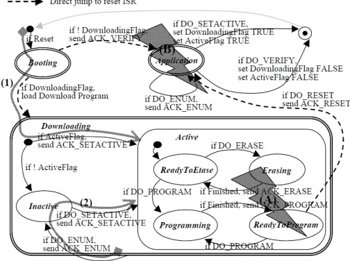
represents the “application incapable of CAN communication” category. Here, ECU state of Flash memory waits in the Downloading-Active state because the new application does not pass the verification phase. In spite of the different causes, ECU remains in Downloading-Active state. Consequently, ECU can wake into Downloading-Active state just by reset as depicted by the path (1) in Figure 5. New Started host PC program initiates new downloading process by sending a DO_ENUM message. The ECU switches to Downloading-Inactive state when receiving the DO_ENUM message as depicted by the path (2) in Figure 6. Eventually, ECU is initialized into the same state as the case when the downloading process starts without any application program. It is inspected that all kinds of faults, which occur after setting the Downloading Flag and the Active Flag to TRUE, can be recovered by the same mechanism through diverse experiments. Furthermore, It is inspected that all kinds of faults, which occur in the handshaking phase, can be recovered just by reset because the application program is not destroyed. Finally, it is confirmed that the proposed protocol can recover all kinds of faults occurring at any phase of CAN flash programming At this moment, it must be reminded that one of the important objectives of CAN flash programming is the ordinary maintenance of EUC software through wide service network. Therefore, to make CAN flash programming practical, disturbances able to occur in loosely controlled casual working environment such as a normal garage should be considered.
Figure 5. Recovery from faults
D. Conclusion And Future Scope
The proposed fault tolerant protocol for CAN flash programming guarantees that ECU can recover from diverse faults by recording the ECU state in EEPROM, which is usual in almost every micro-controller. This paper analyzes possible faults systemically through the fault analysis method. Furthermore, it is ensured that the protocol can be implemented with small source code and small memory consumption. This paper insists that fault tolerance such as the proposed protocol should be considered in developing CAN flash programming standards.
REFERENCES
[1] “Fault Tolerant Protocol for CAN Flash Programming”, Ho Gi Jung1, Jea Young Hwang1, Pal Joo Yoon1 and Jai Hie Kim2 MANDO Corporation,Korea Yonsei University, Korea
[2] “Road vehicles-diagnostic system-keyword protocol 2000”, ISO14230
[3] Jim Samuel, “Developing diagnostics on KWP2000 and CAN”, SAE paper No. 981112, 1998
[4] Kim Lemon, Tammy Dmuchowski and Bruce Emaus, “Introduction to CAN calibration protocol”, SAE paper No. 2000-01-0389, 2000 [5] Frank Voorburg, “Rapid application development for embedded systems using CAN calibration protocol”, SAE paper No. 2002-01-1170, 2002 [6] “XC166 flash-on-the-fly : A concept to flash via CAN”, Application note AP16048 V1.1, www.infineon.com,2004
[7] Sven Deckardt, “Flash kernel programming on an HC12 microcontroller”, Application note AN-IMC-1-002 V1.0, www-vector-informatik.de, 2003 [8] Julien Mothre, “CCP-flashing technical documentation V1.1”,ETAS SAS, Rungis, 2002
[9] Ross McKuckie, East Kilbride, “Flash programming via CAN”, Application note AN1828/D rev. 1, Motorola Inc.,2002