Post-depositional structural changes in clay sediments
HURST, Christopher W
Available from Sheffield Hallam University Research Archive (SHURA) at:
http://shura.shu.ac.uk/7029/
This document is the author deposited version. You are advised to consult the
publisher's version if you wish to cite from it.
Published version
HURST, Christopher W (1987). Post-depositional structural changes in clay
sediments. Doctoral, Sheffield City Polytechnic.
Copyright and re-use policy
Sheffield City Polytechnic Library
ProQuest Number: 10697153
All rights reserved
INFORMATION TO ALL USERS
The quality of this reproduction is dependent upon the quality of the copy submitted.
In the unlikely event that the author did not send a com plete manuscript and there are missing pages, these will be noted. Also, if material had to be removed,
a note will indicate the deletion.
uest
ProQuest 10697153
Published by ProQuest LLC(2017). Copyright of the Dissertation is held by the Author.
All rights reserved.
This work is protected against unauthorized copying under Title 17, United States C ode Microform Edition © ProQuest LLC.
ProQuest LLC.
789 East Eisenhower Parkway P.O. Box 1346
POST-DEPOSITIONAL STRUCTURAL CHANGES IN CLAY SEDIMENTS
CHRISTOPHER W HURST BSc
A thesis submitted to The Council for National
Academic Awards in partial fulfilment of the requirements for the degree of Doctor of Philosophy
Sponsoring Establishment
SHEFFIELD CITY POLYTECHNIC Department of Civil Engineering
Collaborating Establishment
"Possibly many may think that the deposition and consolidation of fine-grained mud must be a very simple matter and the results of little interest. However, when carefully studied experimentally, it is soon found to be so complex a question and the results dependent on so many variables that one might feel inclined to abandon the enquiry were it not that so much of the history of our rocks appears to be written in this language."
CONTENTS
List of Tables (vi)
List of Figures (viii)
Acknowledgements (x)
Abstract (xi)
CHAPTER 1 INTRODUCTION • 1
1.1 The nature of the problem 1
1.2 Organisation of the report 8
CHAPTER 2 FINE-GRAINED SEDIMENTS: TERMINOLOGY
AND CLASSIFICATION 10
2.1 Terminology 10
2.2 Classification 13
CHAPTER 3 PREVIOUS WORK 18
3.1 Fundamental modes of clay microstructure 18 3.2 The microfabric of sedimenting clays 24 3.3 The microfabric of fresh clay sediments 26 3.4 The microfabric of clays and mudrocks 34
CHAPTER 4 DEVELOPMENT OF MICROSTRUCTURE 42
4.1 Environments of deposition 42
4.1.1 Deposition in marine environments 43 4.1.2 Deposition in non-marine environments 46
4.2 Geochemistry of environments 47
4.2.1 Chemical factors in sedimentation (pH, Eh
4.2.2 Chemical reactions of aerobic and anaerobic
environments 50
4.3 Accumulation of organic matter in sediments 51
4.3.1 Biological factors 52
4.3.2 Physical factors 53
4.3.3 Anoxic environments 54
4.4 The influence of clay minerals in microstructure
development 56
4.4.1 The structure of clay minerals 57 4.4.2 The properties of clay minerals 59
4.4.3 Clay colloid activity 62
4.4.4 Interaction between clay minerals and organic
compounds 64
4.5 Fissility in mudrocks - a suggested model for
its development 66
CHAPTER 5 MICROSTRUCTURAL OBSERVATIONS IN MUDROCKS 70
5.1 Introduction 70
5.2 Mudrocks : depositional information 70 5.2.1 Red Shale - Lower Cambrian : Caerfai Series 70 5.2.2 Dolwyddelan Shale - Ordovician : Caradoc Series 71 5.2.3 Cautley mudstone - Ordovician : Ashgillian 73 5.2.4 Stockdale Shale - Silurian : Landoverian 73 5.2.5 Yoredale Shale - Lower Carboniferous : Visean 75 5.2.6 Coal Measure Shales - Upper Carboniferous :
Westphalian A and B 75
5.2.7 Red Lutite - Permo-Triassic : Littleham
5.2.8 Bituminous Shales - Lower Jurassic : Toarcian .79 5.2.9 Oxford Clay - Upper Jurassic : Callovian 79
5.2.10 Kimmeridge Clay - Upper Jurassic : Kimmeridgian 81 5.2.11 Speeton Clay - Lower Cretaceous : Hauterivian 84 5.2.12 Un-named Mudstone - Tertiary : Neogene? 84 5.3 Mudrocks : Statistical analysis 85 5.3.1 Chi-squared goodness of fit test 85
5.3.2 Initial data analysis 87
5.3.3 Results from the test of uniformity 88 5.3.4 Confidence interval results 89 5.3.5 Comparison of data from the same specimen or sample 91
5.3.6 Statistical conclusions 93
CHAPTER 6 EXPERIMENTAL MODEL AND OBSERVATIONS 94
6.1 Previous work 94
6.2 A model for sediment accumulation 96
6.2.1 Physical aspects 97
6.2.2 Chemical aspects 98
6.2.3 Biological aspects 98
6.2.4 Consolidation aspects 98
6.2.5 Laboratory procedure 99
6.3 Experimental programme 99
6.3.1 Clay sedimentation 100
6.3.2 Geo technical data 102
6.4 Statistical analysis 104
CHAPTER 7 DISCUSSION 114
7.1 Introduction 114
7.2 Measurement and analysis of microstructure 115
7.3 Mudrock microstructure 118
7.4 Clay microstructure 121
7.5 Comparison of microstructure in the natural and
laboratory sediments 123
7.6 Geotechnical properties of clay sediments 124
7.6.1 Fresh clay sediments 126
7.6.2 Consolidated clay sediments 126
7.6.3 Laboratory sediments 128
7.7 Authenticity of the laboratory simulation 134 7.8 Clay diagenesis, organic matter and oil generation
in argillaceous sediments 135
7.8.1 Clay sediment diagenesis 136 7.8.2 Clay-organic interaction 137
7.8.3 Oil generation 140
7.9 Validity of the model 141
CHAPTER 8 CONCLUSIONS AND SUGGESTIONS FOR FUTURE RESEARCH 145
8.1 General 145
8.2 Concluding summary 145
8.2.1 Microstructural changes 146 8.2.2 Geotechnical properties 148
8.2.3 Particle orientation 148
BIBLIOGRAPHY 151
APPENDIX I EXPERIMENTAL WORK. A1
APPENDIX II STATISTICAL THEORY A14
APPENDIX III STATISTICAL PROCEDURE A3 7 APPENDIX IV THE PREPARATION AND OBSERVATION OF SAMPLES A45
APPENDIX V MUDROCK SAMPLE LOCATIONS A49
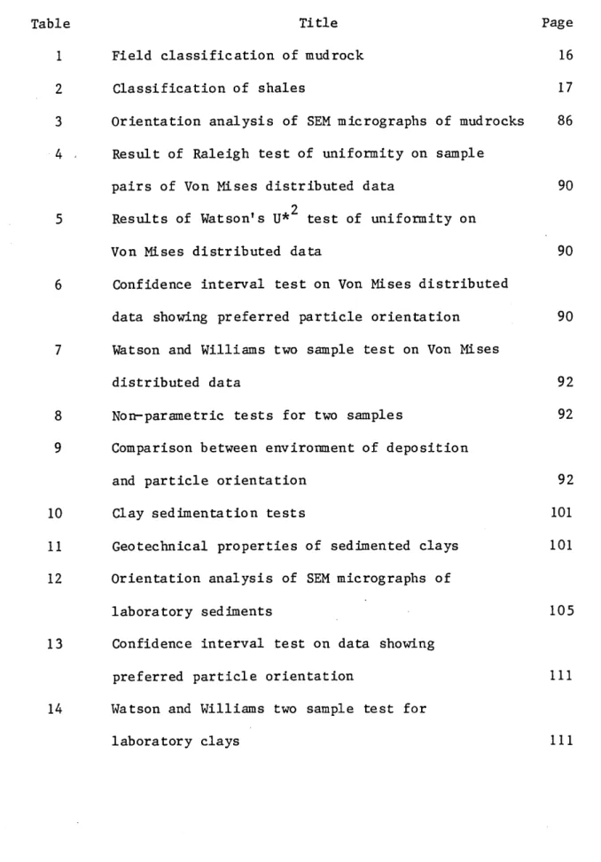
LIST OF TABLES
Table Title Page
1 Field classification of mudrock 16
2 Classification of shales 17
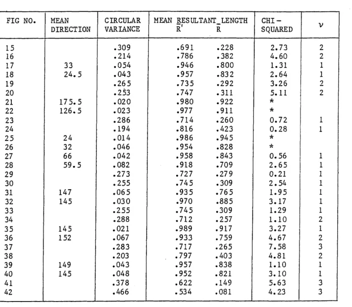
3 Orientation analysis of SEM micrographs of mudrocks 86 4 - Result of Raleigh test of uniformity on sample
pairs of Von Mises distributed data 90 2
5 Results of Watson’s U* test of uniformity on
Von Mises distributed data 90
6 Confidence interval test on Von Mises distributed
data showing preferred particle orientation 90 7 Watson and Williams two sample test on Von Mises
distributed data 92
8 Non-parametric tests for two samples 92 9 Comparison between environment of deposition
and particle orientation 92
10 Clay sedimentation tests 101
11 Geotechnical properties of sedimented clays 101 12 Orientation analysis of SEM micrographs of
laboratory sediments 105
13 Confidence interval test on data showing
preferred particle orientation 111 14 Watson and Williams two sample test for
A1 The maximum likelihood estimate of k for given R in - .
the Von Mises case A25
A2 Critical values of the Rayleigh test of uniformity A28 2
A3 Percentage points of U* A34
Figure
LIST OF FIGURES
Title Page
1 Honeycomb structure
2 Cardhouse structure, saltwater deposit 3 Sediment structures
4 Modes of particle association in clay suspensions 5 Aggregate structure
6 Turbostratic structure 7 Bookhouse or book structure
8 Domain structures "stepped face-to-face" 9 Proposed tentative clay fabric models for
submarine sediment
10 Major environments of organic-rich sediment accumulation
11 Silica tetrahedral and octahedral unit layers 12 Arrangement of unit layers in illite
13 Arrangement of unit layers in kaolinite
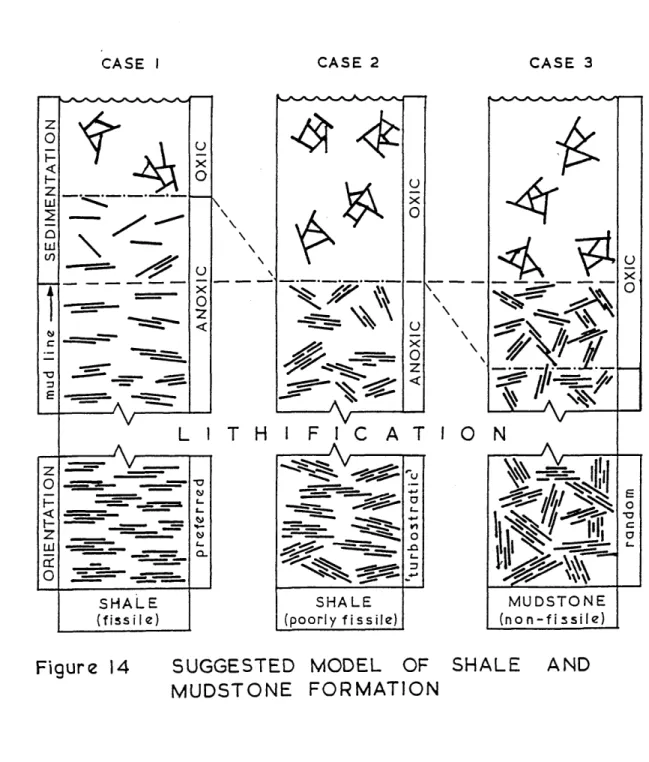
14 Suggested model of shale and mudstone formation 15-42 SEM micrographs of mudrock samples
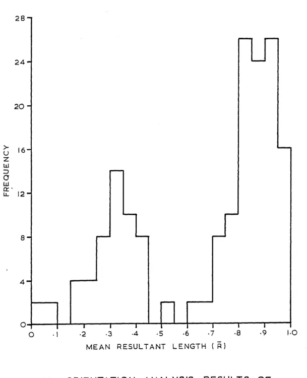
43 Orientation analysis results of mudrock samples 44 SEM micrograph of a pyrite framboid
45-64 SEM micrographs of laboratory sediments 65 Orientation analysis results of laboratory
sediments
66 A comparison of particle orientation in natural and laboratory sediments
67 Typical shear strength and void ratio variations
with depth in a deltaic sediment 127 68 Shear strength and void ratio variations in
UK mudrocks 129
69 Coefficient of consolidation versus mean
resultant length 130
70 Shear strength versus mean resultant length 130 71 Compression curves of illite and kaolinite
sediment 133
72 Comparison of sedimentary models 143 73 SEM micrographs of the Liassic (lower Toarcian) of
Yorkshire 144
A1 Preparation tank and delivery system A3
A2 Column base detail A3
A3 Consolidation cell A4
A4 Monitoring equipment A5
A5 Constant pressure apparatus A5
A6 Settlement-time relationship (test 3) All A7 Void ratio-pressure relationship (test 3) All
A8 The unit circle A16
A9 Mean direction, mean resultant length and
circular variance A16
A10 Density of the Von Mises distribution A23
All Confidence intervals for A24
ACKNOWLEDGEMENTS
The writer would like to express his appreciation to Dr Colin Moon and Dr Mike Leeder (project supervisors) for their help and guidance offered during the course of this research.
The opportunity is taken to extend thanks to other people who gave the writer technical assistance at both Sheffield City Polytechnic and the Royal Military College of Science, and especially to English
China Clays Ltd who provided the clay material.
The thesis has been kindly typed by Mrs J G D Price to whom the writer is greatly indebted.
ABSTRACT (C W HURST)
Post-depositional structural changes in clay sediments
This thesis examines the changes in the microstructure of clays and mudrocks due to the influence of the environment of deposition and subsequent compaction. A sedimentary model is proposed in which the development of fissility in shales and the formation of hydrocarbon source rocks are attributed to the chemical conditions at the time of deposition. The geotechnical properties of fresh sediments are considered and the ability of the depositional environment to affect these properties is assessed.
From a SEM analysis of mudrocks it is shown that there is a correlation between microstructure and the conditions at the time of deposition. Organic-rich shales formed in anoxic environments are characterized by a preferred orientation of microstructure. Mudrocks formed under oxic conditions show a random orientation. This characteristic fabric of shales results from the peptizing capability of certain organic compounds in the environment of deposition and is considered to be a contributing factor to the development of fissility.
A laboratory simulation of the depositional environment is described. Test results show that pure clays sedimented with organic compounds in a marine environment exhibit an increased parallelism of particles compared with those without organic compounds. A mechanism is described whereby the organic compounds are adsorbed onto the clay particle surfaces and promote peptization.
The fabric of sediments obtained under laboratory conditions is found to control the rate of consolidation. Clays with a preferred particle orientation have slower rates of water loss and this is suggested to be an important factor with respect to the formation of under-compacted mudrocks.
CHAPTER 1
INTRODUCTION
1.1 The nature of the problem
The research undertaken in this study is concerned with the micro structure of clays and mudrocks and how this changes from initial deposition to full induration. The geotechnical properties of natural sediments and those prepared artificially are also discussed. In particular a model for the development of fissility is proposed which has a bearing upon the formation of petroleum. The microstructure of clay sediments and mudrocks has been studied by numerous workers, particularly within the last twenty years. The introduction of the electron microscope, with its ability to provide a detailed image of microstructure, did much to encourage this work. One avenue of study which has raised much discussion concerns the phenomenon of fissility, as displayed by those mudrocks called shales. Fissility is defined as the tendency of a rock to split along relatively smooth surfaces parallel to bedding (Pettijohn 1975 p263). The primary cause of fissility has been attributed to a variety of factors and its origin is one fundamental question which has remained unresolved.
are those who suggest that the importance of parallel orientation* is overestimated and that laminations are the controlling mechanism of fissility in shales (Spears 1976, Curtis et al 1980).
There is no disputing that some mudrocks tend to part along laminations but there are instances where this is not the case. Lundegard and Samuels (1980) pointed out that while lamination
generally occurs in fissile mudrocks it is not common for laminated mudrocks to be fissile. They concluded that fissility is not a necessary product of lamination. In some cases where lamination is thought to be the controlling mechanism, it is to be noted that organic material, concentrated in bands, imparts the fissile structure, thus suggesting an organic influence on fissility (Odom 1967). The role that organic matter plays in the formation of fissile shale is central to the model that the author presents in this study.
If one accepts that platy minerals need to be aligned in a preferred direction in order that fissility can occur, then the question arises as to how and when this fabric is produced. There are a number of theories to explain the inducement of parallel orientation
with increasing depth of burial. He concludes that from the evidence of drill cores this is clearly not the case. Compaction does have a role to play but it is more than likely one of bringing closer together the particles of an already established fabric.
It is probable then, that some additional process is at work to assist a preferred alignment to take place prior to any major compaction. Byers (1974) suggested a biogenic origin to fissility in shales. His view was that although fissility is related to the parallel orientation of mineral grains in the rock, this original depositional fabric will only be preserved in the absence of bioturbation. This he suggested is due to abiotic conditions in the original environment of deposition. It is accepted that some disturbance of fabric will arise from benthic activity in the sediment. However it cannot be mere coincidence that the conditions
restricting burrowing infauna are those which have a dramatic effect on sedimenting clay minerals.
connection between the environment of deposition and fissility. *The chemistry of the depositional environment is thus considered to be an important factor in the development of preferred orientation in shales and random orientation in mudstones. The detailed chemistry
involved is not clear but a number of variables such as electrolyte concentration, pH and Eh are thought to be involved.
The suggestion is that the dispersing agents which will allow particles to settle individually and produce a parallel orientated fabric are present in organic-rich marine (or non-marine) environments. Various authors have registered a connection between organic content and shales (Ingram 1953, O ’Brien 1968, Leventhal and Shaw 1980), noting that the organic material imparts a dark colour to the rock. This link is well illustrated by the black shales which are regarded as distinct facies in their own right. It is worth emphasizing that the black shales also tend to be highly fissile. Organic compounds capable of causing dispersion are common in a variety of depositional environments. Examples of which are fjords (Grasshof 1975), fjord like basins (Brown et al 1972), ocean deeps (Degens et al 1961, Deuser 1975) and barred basins as typified by the Black Sea (Degens and Stoffers 1980) .
manner, by oxidation, but is decomposed by the action of anaerobic bacteria in the reducing environment that now exists. It is suggested that clay sediments on entering the anoxic zone have the charges on their particle surface neutralized by the organic material present. The exact mechanism of neutralisation is not yet fully understood but clearly it is dependent on the complex
electrcr-chemistry of clay particles and their immediate surroundings. These neutralised particles are deposited in a dispersed state which on subsequent induration produces the parallel orientated structure conducive to the development of fissility. In 'normal* marine conditions no dispersion occurs and the sediment remains flocculated. This gives rise to a random structure which produces a non fissile -rock on induration. It is not assumed that dispersion by organic compounds is the only means by which fissility is produced in shales but it is considered to be one mechanism of great importance.
The types of organic compound thought responsible for dispersion may also be the source of material for petroleum. There is general agreement that petroleum has a biological origin, although the nature of the source material and the chemistry of its formation is the subject of argument (Colombo 1967). The usual approach to the problem of identifying the source material is to study the chemical similarities between petroleum and the biogenic compounds in
the reducing environment, under anaerobic conditions, that petroleum is said to be formed. Amine salts are known to cause a dispersion of flocculated clay (Van Olphen 1963) and so it is reasonable to infer that amino acids may contribute to both the fissility of shales and petroleum formation. Other organic compounds (sugars, fatty acids, alcohols) are also possible candidates. The evidence thus suggests that a unique relationship exists between the chemical environment which produces a fissile shale and the generation of petroleum. Part of the aim of this study is to explore that relationship.
It is generally recognised that the geochemical environment at the time of deposition also has some bearing on the geotechnical properties of a sediment. The geochemical conditions influence the microstructure adopted by clay particles and this fabric will affect, in particular, the consolidation and shear properties (Rowe 1972) . The term consolidation is used in the engineering sense to m e a n the reduction in volume of a saturated soil due to the expulsion of water. With a flocculated clay the open, random structure would give a higher void ratio that its dispersed counter part under the same overburden stress. In the latter case, due to the preferred orientation, the clay particles have a better chance of coming closer together when water is expelled.
the preferentially orientated one. With regard to strength properties the Delta cores showed a ten times increase in shear strength from the upper high void ratio sediments to the deeper low void ratio ones. They concluded that factors other than depth of
burial and overburden stress influence the microstructure and hence consolidation of a particular sedimentary deposit. One of these factors is the geochemical conditions at the depositional interface.
It must be acknowledged at this point, that in many cases larger scale features are more important, particularly in their effect on mechanical anisotropy, than the microstructural features. In a comprehensive study of the geotechnical properties and parameters of British mudrocks compiled by Cripps and Taylor (1981) it was evident that no one factor is responsible for variations in these properties. Amongst their conclusions they suggested that the removal of overburden (uplift and erosion) has a significant influence on engineering behaviour. A response to the change in overburden stress is the creation of joints and fissures and it is likely that the microstructure together with other factors will influence the orientation of these features.
There are many uncertainties surrounding the nature of formation of clay sediments and mudrocks. The number of variables involved in
of natural sediment accumulation - the environment of deposition. The simulation is not without faults but it illustrates what may be
achieved in the confines of a laboratory using unsophisticated equipment•
1.2 Organisation of the report
The literature survey in Chapter 3 records the various fundamental models of clay microfabric. Recent studies of natural and laboratory prepared samples using the scanning electron microscope (SEM) are presented. Chapter 4 considers some of the environments of deposition in which clays and mudrocks are formed and examines the geochemistry of these environments. On the basis of the evidence presented in this first part of the study a tentative model is suggested for the origin of fissility in shales.
The second part of the study presents the observations and data to support the proposed model. Chapter 5 covers the SEM investigation of sampled mudrocks and tabulates the statistical data for each specimen. The environments of deposition of the various mudrocks are considered with respect to the proposed model. The experimental evidence is given in Chapter 6. The SEM investigation and
statistical data for the laboratory prepared samples are presented together with their geotechnical properties.
Chapter 7 discusses the evidence obtained from both SEM investi gations in relation to the model offered and reviews the possible
The conclusions of the study and a consideration of future research are presented in Chapter 8.
The experimental procedures, equipment details, statistical theory, computer programs and sample records are all presented in the
Appendices.
A study of mudrocks would not be complete without some reference to the confused terminology which has evolved over the years. It is
CHAPTER 2
FINE-GRAINED SEDIMENTS: TERMINOLOGY AND CLASSIFICATION
2.1 Terminology
There is, without doubt, a great deal of confusion over the termi nology used in the description of fine-grained sedimentary rocks. Much of this confusion arises because no widely accepted classi fication of these rocks exists. Attempts have been made to rectify this situation (Underwood 1967, Picard 1971, Lewan 1978, Spears 1980, Lundegard and Samuels 1980, Stow 1981) but since mudrock terminology is often not consistent in its meaning this has led to confusion. An example is the word ’shale' which may be used in a stratigraphic context, as a class name for a sequence of strata
(e.g. Edale Shale), and in a more specific role to define a rock composed of predominantly fine-grained clastic particles. Since the class name of 'Shale' is firmly entrenched in the geological literature (Tourtelot 1960) then most workers accept its dual meaning. The use of the upper-case character helps to reduce any
confusion.
clay dominant rocks regardless of whether fissility is present, or not, Fertl (1977 p 294) defines shale as an "earthy, finegrained, sedimentary rock with a specific laminated character". Again, no reference is made to fissility, Pettijohn (1975 p 261) refers to shale as "a laminated or fissile rock" and does not specify that
fissility must be present. This is the case with Potter et al (1980) whose classification of shale requires only that laminae < 10 mm thick be present. They define fissile simply as a class of parting with thickness between 0,5 and 1,0 mm. Under their classification it is possible for a non-fissile shale to exist. In line with Hedberg, Blatt et al (1980 p 381) confirm that shale is
often used as a word to describe the entire class of finegrained sedimentary rocks in which clay minerals predominate. To confound the issue further, Clark's (1954) definition of a shale includes rocks that are widely accepted as siltstones.
In an attempt to alleviate the confusion surrounding the use of the word 'shale' the term 'mudrock' has been proposed (Lundegard and
Samuels 1980) although this itself has given rise to some debate (de Freitas 1981). It may be argued on two counts that as a term mudrock is ambiguous. Firstly because mud and rock define opposing physical states and secondly because although its name implies rocks of a siliciclastic composition it can also include rocks that are calcareous or siliceaous. In recognition of the latter, biogenic mudrock has been suggested as an appropriate title for carbonates etc (Stow and Piper, 1984).
sedimentary rocks composed predominantly of clay and silt sized siliciclastic minerals, where the latter make up more than 50% of the rock. Its usage is somewhat synonymous with argillaceous rock. Under the heading of mudrock lie a range of unlithified and lithified sediments whose terminology is related to the particle size distribution of the sediment and whether or not lamination and/or fissility are present.
Silt-sized material lies between the upper boundary of clay-size w h i c h is 4 |j.m and the lower bound of sand-size which is 63 (im (Wentworth 1922). It is usual to refer to an unlithified sediment with predominantly silt-sized particles as a silt and one of predominantly clay-size as a clay. There is no reference to the mineralogical composition in this instance and a clay need not necessarily be composed of clay minerals. If the mix of silt and clay sizes is not easily definable then the sediment is often described as a mud.
if definitely silty, siltstones. This broad usage of the word 'shale' is probably responsible for much of the confusion in mudrock terminology.
2.2 Classification
There is a definite requirement for a unified, descriptive classi fication of mudrocks. Existing geological classifications are commonly based upon textural and compositional attributes and are biased towards laboratory analysis. Ideally a classification should rely upon parameters which are recognisable both in the field and in the laboratory.
The splitting character, or fissility, of the rock features predominantly in most classifications. However in the majority of cases fissility only becomes apparent at the surface outcrop and is not always evident in fresh core samples (Lundegard and Samuels 1980). Its manifestation would appear to be time dependent, arising as a response to both weathering and a release of confining stresses. On this basis it would not be appropriate to use fissility alone as a classifying parameter for mudrocks since its presence is temporal.
own. This is not to say that fissility is ignored, but rather’ it becomes a secondary feature as far as sedimentology is concerned, along with colour, mineral content and genetic origin.
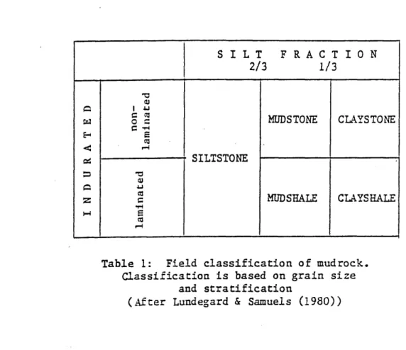
The simplest and most appropriate field method of geological classification is that proposed by Lundegard and Samuels (1980) and is given in Table 1. The classification is based upon quantifying
just two parameters - silt content and lamination. The deter mination of silt content need not be based upon precise laboratory methods. Blatt et al (1980 p 382) have suggested a simple method to define the size boundaries, which can be carried out in the field. With regard to lamination the recognition of a fabric-type lamination is not difficult, but grain size and colour lamination
can pose a problem. The scheme of Lundegard and Samuels suggests 10% laminae as the minimum necessary to qualify as a shale. In the majority of cases this simple type of classification should suffice. Unless a more precise description is required there should be no need to resort to laboratory classifications like those of Picard (1971) and Lewan (1978).
An engineering classification of mudrocks requires a slightly different approach. Since strength properties feature prominantly in an engineering classification then a consideration of anisotropy is necessary. For example fissility has a significant influence on the bulk properties of mudrocks and is of major importance in
geotechnical engineering (Taylor and Spears 1981) .
terms was carried out by Terzaghi (1936). He presented a three-fold division comprising of soft intact clays, stiff intact clays (both free of joints and fissures) and stiff fissured clays. Only the weaker end of the mudrock spectrum was classified. In engineering parlance these mudrocks would most probably be regarded as soils. The reason being that to an engineer a rock is an "aggregate of minerals connected by strong and permament cohesive forces" (Terzaghi and Peck 1967) whereas the weaker mudrocks are easily crumbled in the hand like a soil.
This distinction is not appropriate to this study. To simplify matters the strength parameters of the Working Party Report on rock masses (Anon 1977) have been adopted. Mudrocks span the whole
strength spectrum of soils and rocks and are only distinguished from ’clay sediments' by the fact that the latter may include freshly
deposited material.
Underwood’s (1967) classification takes into account strength properties and he divided shales (which to him were mudrocks possessing fissility) into 'soil-like' which are only compacted and 'rock-like' which are compacted and cemented. The diagenetic bonding of mudrocks is important in engineering classifications but has no significance geologically. A typical engineering classification of mudrocks is given in Table 2.
Chapter 5.
As a postscript to this chapter a comment of the prominance of mudrocks in the geological literature is warranted. The number of
articles published specifically on mudrocks is paltry compared with the other sedimentary rocks. To quote a typical example, in their book Blatt et al (1980) devote about 100 pages to sandstones, 90
pages to carbonates but a mere 30 pages to mudrocks. This ratio is even worse in the general sedimentary journals. This is due, perhaps, to the inherent difficulties with their investigation, such as poor sample recovery from boreholes. Because of their importance both geologically, as petroleum source rocks, and in engineering terms, with respect to foundation and slope problems, it is to be
hoped that more attention is directed to their understanding.
S I L T F R A C T I O N 2/3 1/3
e w <
cd
=3 C z w TJ <U I AJC <3
o s e -h Eco •a<u •u CO c •H s CO MUDSTONE SILTSTONE MUDSHALE CLAYSTONE CLAYSHALE
Table 1: Field classification of mudrock. Classification is based on grain size
and stratification
Siltstone/claystone + Fissility = Shale ’Soil-like* shale ’Rock-like* shale (compaction or subshale) (cemented or bonded)
Clayey shale
(clay shale) 50% or more claysized particles which may or may not be true clay minerals
Clay-bonded
shale Welded by recrystallization of clay minerals, or by other diagenetic bonds
Silty shale 25-45% silt sized particles. Silt may be in thin
layers between clayey shale bands
Calcareous
shale 20-35% CaC03 (Marlsand shaley chalk 35-65% CaC03)
Sandy shale 25-45% sand sized particles. Sand may be in thin
layers between clayey shale bands
Siliceous
shale 70-85% amorphoussilica often highly siliceous volcanic ash (quartzose shale-detrital quartz)
Black shale Organic rich, splits into thin semi-flexible sheets
Ferruginous
shale (potassic shale - 5(25-35% Fe203) - 10% potash)
Carbonaceous
shale Carbonaceous matter(3-15%) tends to bond constituents together and imparts a certain degree of toughness
CHAPTER 3
PREVIOUS WORK
Fine-grained sediments have been estimated to account for 80% of the global rock column (Clarke 1924) and yet comparatively very little work has been devoted to analysing their microstructure. There are obvious reasons for this, namely their poor exposure, extremely fine texture and complex mineral composition. Interest in these sedi
ments has fluctuated with the development of improved techniques to investigate their structure. One of the major improvements was the introduction of the electron microscope and this instrument has be come an essential tool for use in the examination of clays and mudrocks. It is a credit to workers in the era before the appli cation of the electron microscope to fabric studies that their models of clay microstructure are not widely dissimilar to present day concepts,
3.1 Fundamental models of clay microstructure
Evidence from natural and artificial clay sediments suggests that there are many different types of microstructure present in these soils. A number of fundamental models have been proposed and these
are presented here.
(1926) and later modified by Lambe (1953). These structures *are illustrated in Figs. 1 and 2. A subsequent report by Lambe (1958)
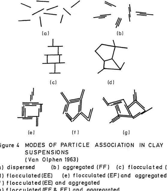
revealed three modes of clay structure whose formation was primarily dependent upon electrolyte concentration (Fig. 3). The importance of electrolyte concentration in controlling the arrangement of clay particles was discussed at length by Van Olphen (1963). His hypo thesis, based upon clay colloid chemistry, predicts a number of possible particle associations (Fig. 4). Von Englehardt and Gaida (1963) proposed a modified cardhouse model which they called an aggregate structure (Fig. 5). The aggregates are composed of many single clay particles having edge-to-face contacts.
A major development in microfabric studies was the introduction of the domain concept (Aylmore and Quirk 1959). A domain is a micro scopic or submicroscopic region within which several clay particles are in parallel array. Domains have also been referred to as stacks, packets, tactoids or clusters by other workers. Aylmore and
Quirk (1960) suggested the term turbostratic structure for a group of domains in a turbulent array (Fig. 6). A more open type of turbostratic arrangement was described by Sloane and Kell (1966) as a bookhouse structure (Fig. 7). Further evidence for the domain assembly was provided by Smalley and Cabrera (1969) who identified a stepped face-to-face particle association (Fig. 8) which was con sidered to be more stable than the book structure of Sloane and Kell.
Figure 1 HONEYCOMB STRUCTURE
(Terzaghi-Casagrande 1925)
Figure 2 CARDHOUSE STRUCTURE, SALT WATER DEPOSIT
(Goldschmidt-Lambe 1953)
(a)salt flocculation (b)non-salt flocculation
I 1
X
/
f (b)
I
I
(d)
(g) (f
Figure
U
MODES OF PARTICLE ASSOCIATION IN CLAY
SUSPENSIONS
( Van Olphen 1963)
(a) dispersed
(b) aggregated (FF) (c) flocculated {E F )
(d) flocculated (EE)
(e) f locculated (EF) and aggregated
(f ) f locculated (EE) and aggregated
(g) f locculated (EF & EE) and aggregrated
Figure 6 "TURBOSTRATIC" STRUCTURE
(Aylmore and Quirk 1960 )
Figure 7 BOOKHOUSE OR BOOK STRUCTURE
( Sloan and Kell 1966)
Figure 8 DOMAIN STRUCTURES "STEPPED
FACE-TO-FACE"
are quite complex. Tan (1959) and Pusch (1970) are two workers 'who have provided 3D impressions of clay particle networks and with the scanning electron microscope true 3D observations are now possible. The time consuminmg process of obtaining data from these 3D images has negated their usefulness to fabric studies. A semi-automatic stereoscopic analysis method has been examined by Tovey (1978) but little commercial development has been forthcoming to date (Tovey, personal communication)•
The distinction between single plate structures of the cardhouse type and the domain structures has been recorded by Barden (1972) . He has suggested that the cardhouse structure is only likely to exist in dilute colloidal suspensions (i.e. during particle settling) and its relevance to consolidated natural clays is questionable. Even at or very near the depositional interface (or mudline) particle clusters will take up the domain arrangement when the clay concentration is high enough (Moon 1972). During settling, pelletization by planktonic organisms (Ernissee and Abbott 1975, McCave 1975, McCall 1979) and agitation of the water will produce domains by the agglomoration of particles. Once domains have undergone some light compaction it is unlikely that they will be destroyed, although with excessive shear a dislocation and slippage between particles could occur. Diagenetic processes force domains very close together to the extent that they become difficult to recognise in highly compacted mudrocks. In laboratory consolidated samples of kaolin slurries McConnachie (1974) identified domains after pressure of 10^ kPa, and they were in fact recognisable from
mudrocks even though they are difficult to detect.
3.2 The microfabric of sedimenting clay
This section will deal with those structures which are believed to be characteristic of dilute clay suspensions, in which the clay particles are settling towards the depositional interface under the influence of gravity alone. Because of the obvious practical diffi culties in direct observation and the problems of fabric disturbance when sampling, the concepts of microstructure at this stage are either theoretical or based upon indirect evidence. Consequently few specific findings have been reported.
The nature of clay particles and their reaction to the chemistry of the depositional environment suggests that certain particle associ ations are possible. As already pointed out, Van Olphen (1963) has contributed much to the understanding of clay particle interactions. He suggested that three different modes of particle association may occur on flocculation: face-to-face (FF), edge-to-face (EF) and edge-to-edge (EE). The FF association is the domain type structure which Van Olphen called an aggregate, whilst the EF and EE modes provide the basis of the cardhouse structure which he considers as flocculated.
According to their model single clay particles, initially scattered thinly about the water medium, form a cardhouse structure of EF con figuration in thickening suspensions. Neutralisation of repulsive surface forces on the faces allow plate to plate (cf FF) floccules to form and thence domain type structures begin to develop.
The flocculation process results in the formation of EE and EF con tacts between either single particles or small domains and the unit
built up by these contacts is called the floe. However, this process is not irreversible and floes may dissociate themselves by dispersion if the environment changes. Whitehouse et al (1960) regarded the settling unit (or floe) as a thermodynamically rever sible assembly which they termed a ’coacervate’. They indicated that the aggregation of clay minerals by saline waters is
reversible. The ’break up' of floes is more likely to occur above the mudline but there is no reason to suggest that it may not happen at or just below the mudline where compaction is minimal.
The flocculation characteristics and hence settling behaviour of a sediment have been attributed to its mineralogy (Whitehouse et al 1960) but this has been challenged by Kranck (1975). In a study of suspended sediments from coastal environments Kranck concluded that particle size rather than mineralogy is the controlling factor. This tends to agree with the work of Packham (1962).
that the EF cardhouse structure was the most likely clay particle
arrangement.
From the limited available evidence it seems likely that both single-plate cardhouse type structures and small domain-like packets (say 2 to 3 particles), which may or may not form structured groups, are present in sedimenting clays. Their stability will depend upon the prevailing conditions of pH, Eh and salinity in the depositional environment. The structures themselves may have a dozen or less particles (or domains) arranged in some form of EF array forming a floccule, which is the settling unit. The floccule has a limiting size which is governed by the comparable settling velocity of the largest individual grains (Kranck 1975) •
3.3 The microfabric of fresh clay sediments
Fresh clay sediments are considered to be those clays which are present at or just below the mudline and, as such, have not suffered significant compaction by superincumbent material. As with sedi menting clays it is very difficult to sample and prepare specimens for observation without disturbance to the fabric. In view of this, lightly compacted sediments are more often studied, and from these observations the fabric of the uncompacted sediment is inferred. The laboratory sedimentation of mono-mineralic clay suspensions has also yielded much data in spite of the situation being artificial.
illitic clays from Scandinavia were to dominate clay microstructure thinking for years. In the marine clays which he examined,
Rosenqvist (1959, 1962) was able to confirm (albeit not too convincingly) the existence of the cardhouse structure, whose formation he attributed to the flocculating effects of electrolytes in the water. Using the then more standard X-ray diffraction method, Raitburd (1960) reported complete random orientations of illite and kaolinite particles in a Quaternary marine clay from the Black Sea, which supported some of Rosenqvist*s observations.
Mitchell (1956) had examined marine clays using optical microscopy and reported that silt particles appeared to float in a clay matrix. This fabric was confirmed by O ’Brien and Harrison (1967) who used
the TEM on illitic marine clays. Even where the silt content exceeded 75% Mitchell noted that the clay particles kept the silt grains apart. He also observed the particle orientation in marine clays to be rather patchy, whereas freshwater deposits tended to have well developed orientation aligned parallel or sub-parallel to the bedding. Freshwater deposits with weakly developed orientation were found to have high contents of fine sand or silt, suggesting a dependence of clay orientation on non clay-size particles.
the time of deposition.
With the arrival of the SEM clay fabric studies progressed rapidly during the 1970s. Smart (1967a, 1969) paved the way for SEM research and produced a comprehensive account of soil structure. His observations showed that both single particle and domain type structures were possible in freshly sedimented clays. Laboratory sedimented samples of illite and kaolinite were examined in an uncompressed state by O ’Brien (1970, 1971, 1972). His SEM studies revealed a fabric consisting of an open network of randomly orientated domains with stepped face-to-face flocculated flakes. He concluded that the gross fabric was similar to the honeycomb or cardhouse models but more face-to-face flocculation was found than had been expected.
well orientated structure of closely packed particles, Doma'ins could not be clearly distinguished in their micrographs. Sides and Barden demonstrated that the surface activity of a clay has a great influence on the resulting fabric.
An interesting study by McConnachie (1974) considered the fabric changes in remoulded kaolin during consolidation. The TEM was used since it proved more suitable for domain and pore size measurements. The original clay structure (pressure: 0.1 kPa) had a high void ratio (5.5) with predominant EE and EF contacts between domains. With increasing pressure void size reduced and some domain orientation was effective. At pressures of 100 kPa bonds between constituent particles of domains ruptured and there was a reduction in size and breadth. This is contrary to the findings of other investigators (e.g. Blackmore and Miller 1961) but McConnachie did not consider it significant. The important fact to note from his experiments was that domains were present from the outset which suggests their presence at the depositional interface.
Kirkpatrick and Rennie (1972, 1973) investigated the structure and stress-strain behaviour of laboratory prepared kaolin slurries using isotropic and anisotropic consolidation. Their findings suggested that anisotropic structure develops at an early stage in Kq con
fabric by controlling the chemistry of the clay-water system and the magnitude and type of consolidation stress path. They confirmed that considerable preferred orientation of particles is induced at
low K consolidation stress values (as low as 200 kPa). The effecto of the initial chemistry was to cause higher degrees of orientation in the dispersed samples than the flocculated ones for a given consolidation stress path. It was found that anisotropically con solidated samples produced a preferred orientation whereas a random orientation arose from isotropic consolidation, and this was true regardless of the initial chemistry of the slurries. X-ray dif fraction methods were used for the fabric assessment but SEM micro graphs did reveal domain formation. In the isotropically con solidated samples domains were composed of face-to-face particle association and their orientation was random (cf turbostratic)•
obtained by precipitation from distilled and salt water. When
precipitated in distilled water kaolinite formed a loosely aggregated microstructure similar to the bookhouse structure. The domains were produced exclusively by FF particle associations and had EF and FF contacts. In contrast, when precipitated in the electrolyte solution a characteristic honeycomb structure was formed of particles in a stepped face-to-face association. Illite was found to have a cardhouse microstructure of mostly single particles with EE and EF contacts.
In a series of reports, Bennett and his co-workers (1977, 1979, 1981) looked at the clay fabric of submarine sediments from the Mississippi Delta. At shallow burial depth (1.4 m) the sediments had a high porosity (max 71%) and the fabric was one of randomly arranged domains in EE and EF contact which closely resembled the turbostratic model of Aylmore and Quirk (1960). The domains were composed of FF clay platelets, forming a nearly perfect stack, and
Mathewson et al (1972) the model suggests that at very high void ratios (>3.0) single plate-like particles are present (rather than domains) which develop long chains of EE and stepped FF contacts, connecting cardhouse type floes (Fig. 9). At high void ratios ( > 2 . 5 ) randomly arranged domains in near perfect stack are formed with EE and EF contacts. Beyond this stage lower void ratio sedi ment (<1.2) is achieved by FF particle packing with a high degree of preferred orientation.
V
single platelike particles and chains very high void ratio> 3-0
domain particles and chains high void ratio > 2-5
very low void ratio
<
1- 2transition occurs at the depositional interface where there is a sudden change in clay mineral volume concentration. This could account for the reason why there is a considerable loss of water in
the first few centimetres of fresh clay sediments (Moore 1932, Ziillig 1956). It is unlikely that the increase in volume con centration is the only mechanism operative to cause domain formation. Other controls, such as the electrochemical conditions and benthic biological processes, should not be overlooked.
3.4 The microfabric of clays and mudrocks
The change from a fresh sediment to clay soil and subsequently a mudrock is not as clearly defined as the previous transition from a sedimenting clay. For this study the guidelines of the Working Party Report (Anon 1977) have been adopted, as explained in Chapter
2, giving a range of sediments from soft clays to very strong rocks. The change in microstructure within these limits is partly the result of compaction processes which force out the interstitial water and bring the domains closer together. In doing so, there is an increase in domain orientation and the likelihood of more particles being incorporated into each domain (Moon 1972). Inter related with these mechanical changes are the normal chemical trans formations associated with the diagenetic processes (Dunoyer de Segonzac 1970, Weaver and Beck 1971).
between compaction and depth of burial were explored by Weller
(1959) who considered that the colloidal properties of clay are important with respect to compaction. Excellent reviews by Meade (1964, 1966), Mtiller (1967) and Rieke and Chilingarian (1974) discuss the many aspects of clay sediment diagenesis with some references to microstructural change. Skempton (1970) presented a valuable study on the gravitational compaction of a variety of
clays, relating this to certain geotechnical properties, but did not include details of microstructure.
A major contribution to clay fabric studies has come from the field of geotechnics, which has long recognised the profound effect of particle arrangements upon the engineering properties of clay soils. Terzaghi (1925) and Casagrande (1932) provided the early impetus to this work which was followed up by Hvorslev (1938) and Lambe (1953). Several workers have attempted to correlate geotechnical properties
with microstructure (Mitchell 1956, Trollope and Chan 1960, Cheetham 1971, Bennett et al 1977). However, as other factors (e.g. fissures) more often have an overriding influence on the in-situ strength of soils and rocks, the interest in microstructure from the engineer’s point of view has diminished. This is not the case with some sensitive clays, though.
Smart 1967). It is logical that the amount of water present will influence the ability of particles to reorientate. Martin (1966) has shown in consolidation experiments with kaolinite that high initial water contents produced an increase in the degree of preferred orientation at low stress levels (150 kPa). Meade (1966)
reviewed the work of many authors on the role of compaction in producing preferred orientation and concluded that most of the orientation develops very early under the first few metres of
overburden.
McConnachie (1974) found that the preferred orientation of kaolinite
domains increased with pressure up to 10 kPa and thereafter remained essentially constant. This low value agrees closely with that of Morgenstern and Tchalenko (1967) , who found no improvement in orien tation above a pressure of 10.8 kPa. As consolidation proceeds, McConnachie observed that domains were able to move freely and become more closely packed. Rotation rather than rupture at points of contact accounted for the increase in preferred orientation. It was found that EF contacts decreased in number at the expense of FF contacts. At pressures of 10"* kPa inter-domain contacts were mostly EE and EF, although the degree of preferred orientation was still less than perfect. In contrast to other workers (Blackmore and Miller 1961) McConnachie did not find that domains increased in size as consolidation progressed.
In a comparable study Bowles et al (1969) consolidated natural
a progressive change in particle orientation during the laboratory consolidation tests. A distinct alteration in microstructure was found to occur between 50 and 400 kPa. At the upper stress level
there was a dense packing of particles as opposed to the previous open arrangement. A significant feature was that in spite of the large decrease in void ratio (2.2 to 1.3) there was no noticeable development of preferred orientation. Micrographs of samples sub jected to the maximum stresses (3100 and 6300 kPa) showed a strong development of preferred particle orientation, although localised areas of random orientation existed. On the basis of their limited observations Bowles et al concluded that random orientation is likely to be retained over the greater part of the reduction in void ratio •
Bennett et al (1977) noted that the void geometry of deeply buried clays is quite different from that of the overlying high-porosity
sediment. The deeply buried low-porosity clays were characterised by a strong preferred particle orientation of domains and continuous chains with associated thin voids, although significant numbers of domains did deviate from the preferred direction. Seme of these obliquely orientated domains were in association with larger voids, which could possibly be holes left by dislodged silt particles. Sediments with high silt and fine sand contents do have less tendency for parallel orientation (Mitchell 1956).
The overwhelming evidence is that compaction produces an increase in the parallelism of particles. The most efficient way of producing a low-porosity sediment is by FF particle packing which naturally results in a high degree of preferred orientation. The domain structure has been repeatedly observed in compacted clay but the nature of domain interaction and orientation is very complex. Collins and McGown (1974) encountered different particle arrangements existing side by side in the same soil. Although in general, they found that bookhouse and stepped flocculated arrange ments were more common in marine soils, whilst brackish water soils
tended to have dispersed or turbostratic arrangements.
some detail was Ingram (1953). He associated fissility with a parallel arrangement of clay particles which was increased by the presence of organic matter. In his study Ingram identified three distinct breaking characteristics: massive, flaky-fissile and flaggy fissile. The difference between a flaky or flaggy shale was
attributed to the nature of the cementing agent. Ingram used a light microscope for his observations and utilised the optical properties of clays, such as birefringence, to determine particle
orientation. White (1961) confirmed that fissility in shales is dependent on preferentially orientated clay particles and suggested that its origin lies within the chemical environment at the time of sedimentation. Odom (1967) also concluded that a high degree of preferred orientation of clay particles is evident in shales, which gives rise to the fissile structure. The work of White and Odom was undertaken using X-ray diffraction techniques.
Early electron microscope studies of shale fabric with the TEM were
magnifications.
O ’Brien (1970) concluded that fissility arises from the deposition
of clay in a dispersed state or from the collapse of clay floccules under the weight of overburden. The former view is endorsed by Moon (1972) and Moon and Hurst (1984). O'Brien noted that fissility was best developed in illitic black shales in which nearly perfect parallelism of clay flakes occurred. He suggested that the presence of adsorbed organic molecules promoted sedimentation in a dispersed state by their ability to neutralise the surface charges on clay particles. Non-fissile mudrocks were found to have a random orientation of clay flakes.
There is sufficient evidence to substantiate the important role played by benthic organisms in altering sediment fabric. Cluff (1980) showed that the variation in bulk fabric of the New Albany Shale Group was governed primarily by burrowing benthic organisms. Rhoads and Boyer (1982) presented a review of the effects of marine benthos on the physical properties of sediments. In a recent paper by O ’Brien (1987) the effects of bioturbation on shale fabric were discussed. He found that when viewed on the SEM, bioturbated fabric was seen to be very similar to the fabric of mudstones formed from flocculated clay. The only distinguishing feature was the lack of
CHAPTER 4
DEVELOPMENT OF MICROSTRUCTURE
Soils and most sedimentary rocks are particulate in nature consisting of an assortment of mineral grains. The manner in which these grains are spatially arranged determines the overall microstructure. In clastic sedimentary rocks the microstructuve owes its development to both the genetic origin of the rock and also the composition of its constituent minerals. The environment within which the particles are deposited is the first stage to a number of
processes that will help to determine microstructure. The important aspects of the environment are the physical, chemical and biological conditions. These three mutually dependent parameters are reviewed. The response of the particles to these conditions will depend upon the type of particle forming the sediment. In the environments considered in this study the most influential particles are the clay m i n e r a l s . How the clay minerals behave and their role in the
development of mudrock microstructure is explained in the model presented here.
4.1. Environments of deposition