http://dx.doi.org/10.4236/epe.2013.510065
Increasing Dye-Sensitized Solar Cell Efficiency by ZnO
Spin-Coating of the TiO
2
Electrode: Effect of ZnO Amount
Fahd Al-Juaid, Amar Merazga*
PhysicsDepartment, Faculty of Science, Taif University, Taif, Saudi Arabia Email: *[email protected]
Received August 29, 2013; revised September 29, 2013; accepted October 6,2013
Copyright © 2013 Fahd Al-Juaid, Amar Merazga. This is an open access article distributed under the Creative Commons Attribution License, which permits unrestricted use, distribution, and reproduction in any medium, provided the original work is properly cited. In accordance of the Creative Commons Attribution License all Copyrights © 2013 are reserved for SCIRP and the owner of the intellectual property Fahd Al-Juaid, Amar Merazga. All Copyright © 2013 are guarded by law and by SCIRP as a guardian.
ABSTRACT
This paper is concerned with the improvement of dye-sensitized solar cell (DSSC) efficiency upon ZnO-coating of the TiO2 electrode. Sol-gel ZnO of controlled amount by varying the number of sol drops during spin-coating is shown to
increase the DSSC efficiency. The highest efficiency is obtained at a single sol drop with enhancement of 40%, while beyond this amount the efficiency falls down sharply to zero. Based on measured optical absorption spectra of the dif-ferent dye-loaded electrodes, it is concluded that this amount of ZnO sol corresponds to the thinnest layer that can cre-ate the energy barrier to minimize the electron recombination rcre-ate without seriously affecting the dye adsorption effi-ciency of the TiO2 film.
Keywords: ZnO Spin-Coating; Dye-Sensitized Solar Cell; Efficiency
1. Introduction
DSSCs based on nanocrystalline TiO2 have attracted
ex-tensive attention in academic research and industrial ap-plication, since O’Regan et al. reported their break- through discovery in 1991 [1]. They may offer an alter-native to conventional semiconductor solar cells due to their low cost and relatively high efficiency.
Spin-coating is a simple deposition technique to pro-duce desired nanostructured materials in the form of thin films. It is often applied in connection with the sol-gel method [2-5] and consists of a preparing solution by mixing the precursor of the desired material with a sol-vent and adding a stabilizing substance. The solution, kept under continuous magnetic stirring for a certain pe-riod of time at a certain temperature, should contain sus-pended particles of the material which are subsequently spin-coated and sintered onto a substrate.
Most applications of the sol-gel spin-coating method to ZnO are related to the study of film properties, while only a few are related to ZnO DSSCs [6,7]. However, the deposition of a ZnO layer by spin-coating on the surface of the nanoporous TiO2 electrode of a DSSC is an active
issue related to surface treatment of TiO2 electrodes by
thin metal oxide films to improve the DSSC photovoltaic properties [8-13]. Kao et al. [13] used the sol-gel spin- coating technique to fabricate TiO2 DSSCs and ZnO-
modified TiO2 DSSCs. They applied multilayer coating
for the TiO2 to reach the required thickness of a nano-
porous film and a monolayer for the ZnO to coat the TiO2 film. The photovoltaic parameters were all found to
increase upon ZnO spin-coating, resulting in the increase of the DSSC efficiency from 2.5% to 3.25%.
In this paper, we examine the effect of varying the amount of ZnO, as expressed by the number of sol drops during coating, on the efficiency of the DSSC. The varia-tion of measured efficiency with ZnO amount shows a remarkable increase by about 40% at the ZnO amount of a single drop followed by a sharp decrease to 0%. While the efficiency increase can be attributed to the energy barrier created by the ZnO layer, which reduces the rate of electron recombination back to dye molecules and electrolyte species [12-14], the decrease of efficiency with further increasing ZnO amount is attributed to the decrease of dye-adsorption efficiency of the TiO2 film
due to screening by larger amount of ZnO.
2. Experiment
*Corresponding author. A ZnO layer was deposited on the surface of TiO
elec-trode (Solaronix) by the sol-gel spin-coating technique. Zinc Acetate (Zn(CH3COO)2·2H2O) was used as a
pre-cursor at a concentration of 0.4 M in the solvent 2-meth-oxyethanol. Mono-ethanolamine was added drop wise as a stabilizer until satisfying a molar ratio of 1 with the precursor, while the solution was being heated at 60˚C under continuous magnetic stirring. The prepared solu-tion containing suspended ZnO nanoparticles is kept in a clean and firmly closed flask before spin-coating. The spin-coater (SPS Spin-150) is adjusted to run at a speed of 3000 rpm for 30s to produce reasonable thin films.
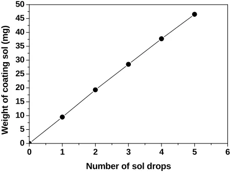
The deposited ZnO amount is monitored by the num-ber of ZnO sol drops injected through the needle of a “smart” dispenser by carefully advancing the plunger into the barrel. In Figure 1, we plot the weight (mg) of released ZnO sol amount versus the contained number of drops.
Such a calibration of the sol dispenser clearly indicates that the drops are identical with a homogeneous material of about the same weight. It also indicates that the num-ber of drops in the released sol content is proportional to its weight, and therefore the number of drops is reliable as a parameter to monitor the coating ZnO amount. The ZnO-coated TiO2 electrodes are annealed at 450 K for
one hour.
Ruthenium-based dye (C26H20O10N6S2Ru) known as
N3 (Solaronix) is used to sensitize the bare and ZnO- coated TiO2 electrodes by immersing in 3 × 10⁻⁴ M
etha-nolic solution for 24 hours. Before immersing the elec-trode, half cm of the material was peeled off from one side to leave uncovered the FTO for electrical contact. Another FTO-glass substrate coated with platinum cata-lyst (Solaronix) is assembled as a counter-electrode against the ZnO-modified dye-loaded electrode by means of two paper clips. Iodide-based electrolyte (Solaronix Iodolyte R-100) containing Iodide/Triodide Redox couple with 100 mM tri-iodide concentration is injected through a capillary channel originally drilled across the counter- electrode. The illuminated area of 1 cm2 through the FTO-
glass substrate is determined using a mask from black tape.
The I-V characteristics of the DSSCs are measured using a photovoltaic system consisting of a solar simula-tor (Solar-Light) and an electrometer (Keithley 2400). The latter is computer-controlled to acquire and plot the I-V data, while AM1.5-filtered light from the 300 W- Xenon lamp of the solar simulator shines the DSSC at a power density Pi = 100 mW/cm2. The absorbance spectra
of the different films and dye solutions are measured by means of a UV/VIS/NIR spectrophotometer (Jasco V- 570).
3. Results and Discussion
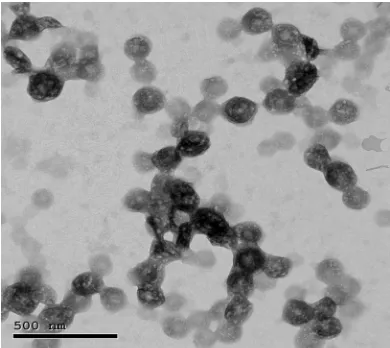
A TEM image of the prepared 0.4 M-ZnO colloidal solu-
0 1 2 3 4 5 6
0 5 10 15 20 25 30 35 40 45 50
Wei
g
ht
of
coa
ti
n
g
sol
(m
g)
[image:2.595.312.537.87.256.2]Number of sol drops
Figure 1. Calibration of the ZnO sol dispenser: Weight of coating ZnO sol against contained number of drops.
tion is shown in Figure 2 to identify the nature and size of the coating ZnO particles prior to optical and photo-voltaic characterization of the ZnO-coated electrodes and DSSCs. Well observed crystallites with average size of 100 nm are illustrated. Song et al. [15] have reported similar TEM-observed crystallites of ZnO prepared by the same sol-gel method as described above.
Figure 3 shows the I-V characteristics of DSSCs with ZnO-coated TiO2 electrodes prepared at five different
ZnO amounts (1 - 5 drops). The characteristic of the DSSC with uncoated TiO2 electrode is also shown for
comparison. In Table 1, we present the PV parameters extracted from the I-V curves of Figure 3. With a single drop of ZnO sol, there is a clear enhancement of the short circuit photocurrent JSC from 5.73 mA/cm2 to 7.01 mA/cm2,
while a small shift upward from 0.58 to 0.65V is ob-served for the open circuit voltage VOC and a practically
unchanged fill factor 62.5% is found at this level of ZnO amount. Further increase of the ZnO amount causes JSC
to fall drastically to zero. VOC shows a small decrease to
0.54 V at the amount of 2 drops, whereas FF still re-mains unchanged. Beyond this range, both VOC and FF
decrease remarkably. The resulting conversion efficiency
η = [(FF × JSC × VOC)/Pi] is presented in the last column
of Table 1, where a maximum η~3% is found at the ZnO amount of 1 drop followed by a sharp decrease.
It is known in the literature that the presence of a metal oxide layer deposited on the TiO2 electrode with a lower
electronic affinity (higher minimum energy level of the conduction band), such as for the ZnO case, creates an energy barrier that can prevent the injected electrons from the dye to recombine back to dye molecules or electrolyte species [12-14].
Figure 2. Suspended 0.4 M-ZnO particles as observed by TEM.
0.0 0.1 0.2 0.3 0.4 0.5 0.6 0.
0 1x10⁻³ 2x10⁻³ 3x10⁻³ 4x10⁻³ 5x10⁻³ 6x10⁻³ 7x10⁻³
7
Ph
ot
o
c
ur
ren
t den
s
it
y (
A
/c
m
2 )
Voltage (V)
Uncoated TiO
2
ZnO-coated TiO
2
1 drop
[image:3.595.314.529.279.441.2]2 drops 3 drops 4 drops 5 drops
Figure 3. I-V-characteristics of ZnO-coated TiO2 DSSCs at different ZnO amounts (1 - 5 drops) and that of the DSSC with uncoated TiO2 electrode.
Table 1. PV parameters for five DSSCs with ZnO-coated TiO2 electrodes prepared at five different ZnO amounts (1 - 5 drops) and the DSSC with uncoated TiO2 electrode.
PV parameters ZnO amount:
(No of sol drops)
JSC (mA/cm2) VOC (V) FF (%) η (%)
0 1 2 3 4 5
5.73 0.576 7.01 0.654 1.40 0.536 0.179 0.386 0.084 0.337 0.174 0.209
62.6 62.3 63.1 46.7 40.1 25.1
2.07 2.86 0.47 0.03 0.011 0.009
able metal oxide layer. Figure 4 shows the dark I-V cha- racteristics of the DSSCs for the five different amounts (1 - 5 drops) of ZnO, as compared to the dark I-V curve corresponding to the uncoated TiO2 electrode. In the dark,
the electron injection from the dye is totally absent and the current is limited to electron diffusion from the TiO2
semiconductor to the electrolyte [18]. As we increase the ZnO amount, the current decreases and requires the as-sistance of a higher voltage to regain the value of the bare TiO2 case. In other words, the electrons require
higher voltages to overcome energy barriers created by larger amounts of spin-deposited ZnO.
The photocurrent and the DSSC efficiency show sharp decreases with increasing ZnO amount above 1 drop (Table 1). The reasonable cause of this must be a sharp decrease of the electron injection rate as a result of the decrease of dye-adsorption efficiency of the TiO2 film.
The factors at the origin of this decrease can be revealed by the measurement and comparison of the absorbance spectra of the different ZnO-coated TiO2 films with
loaded dye. In Figure 5, we present the absorbance spec-
0.0 0.1 0.2 0.3 0.4 0.5 0.6 0.7 0.8
-5x10⁻³ -4x10⁻³ -3x10⁻³ -2x10⁻³ -1x10⁻³ 0
C
u
rre
n
t d
e
n
s
ity
(A
/c
m
2 )
Voltage (V)
Uncoated TiO2 ZnO-coated TiO
2
[image:3.595.60.285.297.472.2]1 drop 2 drops 3 drops 4 drops 5 drops
Figure 4. Dark I-V characteristics of the DSSCs with ZnO spin-coated TiO2 electrodes for 5 different ZnO amounts (1 - 5 drops) as compared to that of the DSSC with uncoated TiO2 electrode.
400 450 500 550 600 650 700 750 800
0.00 0.25 0.50 0.75 1.00 1.25 1.50 1.75 2.00
Ab
so
rb
a
n
ce
(
a
rb
. u
n
it
)
Wavelength (nm)
Dye-loaded ZnO-coated TiO2 films
1 drop
2 drops 3 drops
5 drops
uncoated TiO2
Bare films
TiO2
ZnO
[image:3.595.317.527.503.668.2] [image:3.595.58.286.556.651.2]tra of 4 different dye-loaded TiO2 films pre-coated by
ZnO using 4 different amounts (1, 2, 3 and 5 drops). The absorbance spectra of the dye-loaded uncoated TiO2 and
the bare TiO2 and ZnO films with no loaded dye are also
shown for comparison.
It is noticeable that the spectrum of the bare TiO2 film
(solid line) is much lower than that of the dye-loaded TiO2 film (curve with symbol ■), which means that the
dye molecules form the main light absorber in the visible range. Figure 5 contains also the absorbance spectrum of the bare ZnO film (dashed line) as spin-coated on FTO-glass substrate, which is even lower than that of the bare TiO2 film. Therefore, one would expect that the dye
molecules will still form the main absorber in the pres-ence of the coating ZnO layer and that the spectra of the dye-loaded ZnO-coated TiO2 films will be similar to that
of the dye-loaded uncoated TiO2 film. In contrast, the
coating of the TiO2 film using a single sol drop results in
a much higher spectrum (red curve) than that of the un-coated TiO2 film.
In fact, the chemical instability of ZnO against acidic dye molecules results in partial dissociation of Zn2+ ions
from ZnO particles during the dye-loading process [5,19]. The Zn2+-dye aggregates thus formed on the TiO
2 film
should, therefore, be responsible of the observed excess absorption in this case. This light loss by Zn2+-dye
ab-sorption does not affect the photocurrent because the one-drop ZnO layer is so thin that the dye adsorption efficiency of the TiO2 film is still high and not seriously
affected by the ZnO coating. Yet, the required energy barrier to minimize the rate of electron recombination is established, causing the enhancement of photocurrent and DSSC efficiency as detailed above (Figure 3 and Table 1). With increasing the amount of ZnO, this will partially screen the dye molecules from being efficiently adsorbed into the pores of the TiO2 film. The effective
dye-covered area reduces and the electron light harvest effi ciency reduces as a consequence. The ZnO precursor concentration of 0.4M used in this study is high enough, so that only a second drop of ZnO sol can cause a re-markable reduction in the dye adsorption and light har-vest efficiency. Thereby, the DSSC photocurrent (Figure 3, green curve) shifts well below that of the uncoated TiO2 case (Figure 3, black curve), and the DSSC
effi-ciency reduces to about 0.5% (Table 1). Further increase of the ZnO amount to 3 and 5 drops will vanishingly re-duce the dye-adsorption efficiency, resulting in absorb-ance spectra even lower than that of the bare TiO2 film
(Figure 5, purple and brown curves). The ZnO layer will entirely screen the dye and one should rather consider dye adsorption by the ZnO which is known to be of much lower efficiency than that of the TiO2 [20].
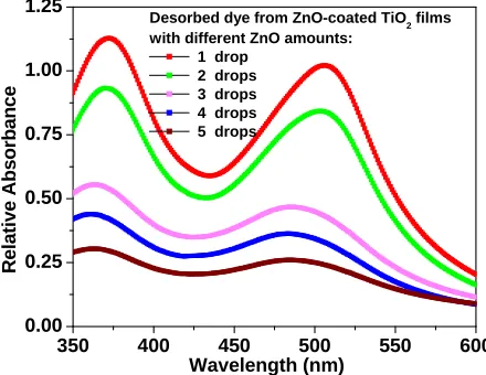
An estimation of the amount of adsorbed dye in the ZnO-coated TiO2 electrodes can be achieved by
pro-ceeding with the dye desorption technique [21,22]. Fig-ure 6 shows the absorbance spectra for solutions of de-sorbed dye from these ZnO-coated TiO2 electrodes. The
solution for dye desorption consists of 4 ml of 0.1M NaOH and ethanol, mixed at equal volumes, in which the dye-loaded electrode is immersed. As can be observed, the lower the amount of ZnO, the higher is the absorb-ance of the desorbed dye. Since the absorbabsorb-ance intensity is proportional to the amount of desorbed dye in the solu-tion, this means that the amount of adsorbed dye is higher in the TiO2 film with lower amount of coating
ZnO. However, the decrease of TiO2 dye-adsorption
effi-ciency with increasing ZnO amount is not the only factor to account for the sharp fall of the DSSC efficiency, but also the increase of light loss due to absorption by ZnO particles and Zn-dye aggregates (Figure 5).
While the present study has led to an optimization of the ZnO amount in terms of number of drops of the coat-ing sol, further work for more enhancement of the DSSC efficiency can be achieved by decreasing the ZnO pre-cursor concentration below 0.4 M [12].
4. Conclusion
The sol-gel spin-coating method is applied to deposit a ZnO layer on the surface of TiO2 electrode in order to
increase the efficiency of the corresponding DSSC. The influence of ZnO amount, as monitored by the number of coating sol drops is emphasized. I-V characteristics of five ZnO-coated TiO2 DSSCs with different ZnO amounts
(1 - 5 drops) are compared to that of uncoated TiO2
DSSC. The results show an increase of η at a single sol drop with enhancement of about 40% followed by a sharp decrease to 0% with further increase of ZnO amount. The efficiency increase is due to the energy bar-rier created by the coating thin ZnO layer, which reduces the rate of electron back-recombination to dye molecules
350 400 450 500 550 600
0.00 0.25 0.50 0.75 1.00 1.25
R
e
la
tive Abs
o
rb
an
ce
Wavelength (nm)
Desorbed dye from ZnO-coated TiO2 films
with different ZnO amounts: 1 drop
[image:4.595.312.532.537.707.2]2 drops 3 drops 4 drops 5 drops
and electrolyte species. The sharp decrease of η is attrib-uted to reduced dye adsorption efficiency of the TiO2
film due to screening by larger ZnO amount.
5. Acknowledgements
The authors acknowledge financial support from Taif University for the project No. 1434-2702.
REFERENCES
[1] B. O’Regan and M. Gratzel, “A Low-Cost High Effi- ciency Solar Cell Based on Dye-Sensitized Colloidal TiO2 Films,” Nature, Vol. 353, 1991, pp. 737-740.
http://dx.doi.org/10.1038/353737a0
[2] S. Ilican, Y. caglar and M. Caglar, “Preparation and Cha- racterization of ZnO Thin Films Deposited by the Sol-Gel Spin-Coating Method,” Journal of Optoelectronics and Advanced Materials, Vol. 10, No. 10, 2008, p. 2578. [3] D. Raoufi and T. Raoufi, “The Effect of Heat Treatment
on the Physical Properties of Sol-Gel Derived ZnO Thin Films,” Applied Surface Science, Vol. 255, No. 11, 2009, pp. 5812-5817.
http://dx.doi.org/10.1016/j.apsusc.2009.01.010
[4] M. Smirnov, C. Baban and G. I. Rusu, “Structural and Optical Characteristics of Spin-Coated ZnO Thin Films,”
Applied Surface Science, Vol. 256, No. 8, 2010, pp. 2405- 2408. http://dx.doi.org/10.1016/j.apsusc.2009.10.075 [5] K. Balachandra and P. Raji, “Synthesis and Characteriza-
tion of Nano ZnO by Sol-Gel Spin-Coating,” Recent Re- search in Science and Technology, Vol. 3, No. 3, 2011, p. 48.
[6] Y.-J. Shin, et al., “Enhancement of Photovoltaic Proper- ties of Ti Modified Nanocrystalline ZnO Electrode for Dye-Sensitized Solar Cells,” Bulletin of the Korean Che- mical Society, Vol. 26, No. 12, 2005, pp. 1929-1930. [7] M. C. Kao, H. Z. Chen and S. L. Young, “Effects of Pre-
Annealing Temperature of ZnO Thin Films on the Per- formance of Dye-Sensitized Solar Cells,” Applied Phys- ics A, Vol. 98, No. 3, 2010, pp. 595-599.
http://dx.doi.org/10.1007/s00339-009-5467-9
[8] D. B. Menzies, et al., “Modification of Mesoporous TiO2 Electrodes by Surface Treatment with Titanium (IV), In- dium (III) and Zirconium (IV) Oxide Precursors,” Nano- technology, Vol. 18, No. 12, Article ID: 125608. http://dx.doi.org/10.1088/0957-4484/18/12/125608 [9] S. Wu, et al., “Improvement in Dye-Sensitized Solar Cells
Employing TiO2 Electrodes Coated with Al2O3 by Reac- tive Direct Current Magneton Sputtering,” Journal of Power Sources, Vol. 182, No. 1, 2008, p. 119.
[10] S. Wu, et al., “Enhancement in Dye-Sensitized Solar Cells Based on MgO-Coated TiO2 Electrodes by Reactive DC Magnetron Sputtering,” Nanotechnology, 2008. [11] L. Li, et al., “Improved Performance of TiO2 Electrodes
Coated with NiO by Magnetron Sputtering for Dye-Sen-
sitized Solar Cells,” Applied Surface Science, Vol. 256, No. 14, 2010, p. 4533.
[12] Y. Liu, et al., “Efficiency Enhancement in Dye-Sensitized Solar Cells by Interfacial Modification of Conducting Glass/Mesoporous TiO2 Using a Novel ZnO Compact Blocking Film,” Journal of Power Sources, Vol. 196, No. 1, 2011, pp. 475-481.
http://dx.doi.org/10.1016/j.jpowsour.2010.07.031 [13] M. C. Kao, H. Z. Chen and S. L. Young, “Effects of ZnO-
Coating on the Performance of TiO2 Nanostructured Thin Films for Dye-Sensitized Solar Cells,” Applied Physics A, Vol. 97, No. 2, 2009, pp. 469-474.
http://dx.doi.org/10.1007/s00339-009-5244-9
[14] S. S. Kim, J. H. Yum and Y. E. Sung, “Improved Per- formance of a Dye-Sensitized Solar Cell Using a TiO2/ ZnO/Eosin Y Electrode,” Solar Energy Materials and So- lar Cells, Vol. 79, No. 4, 2003, pp. 495-505.
http://dx.doi.org/10.1016/S0927-0248(03)00065-5 [15] Y. Song, M. Zheng, L. Ma and W. Shen, “Anisotropic
Growth and Formation Mechanism Investigation of 1D ZnO Nanorods in Spin-Coating Sol-Gel Process,” Journal of Nanoscience and Nanotechnology, Vol. 10, No. 1, 2010, pp. 426-432. http://dx.doi.org/10.1166/jnn.2010.1724 [16] H. Yu, S. Zhang, H. Zhao, G. Will and P. Liu, “An Effi-
cient and Low-Cost TiO2 Compact Layer for Performance Improvement of Dye-Sensitized Solar Cells,” Electrochi- mica Acta, Vol. 54, No. 4, 2009, pp. 1319-1324. http://dx.doi.org/10.1016/j.electacta.2008.09.025
[17] S. Wu, et al., “Improvement in Dye-Sensitized Solar Cells with a ZnO-Coated TiO2 Electrode by rf Magnetron Sputtering,” Applied Physics Letters, Vol. 92, No. 12, 2008, Article ID: 122106.
http://dx.doi.org/10.1063/1.2903105
[18] M. Penny, T. Farrell, G. Will and J. Bell, “Modeling In- terfacial Charge Transfer in Dye-Sensitized Solar Cells,”
Journal of Photochemistry and Photobiology A: Chemis- try, Vol. 164, 2004, p. 41.
[19] I. Bedja, P. V. Kama, X. Hua, P. G. Lappin and S. Hot- chandani, “Photosensitization of Nanocrystalline ZnO Films by Bis (2,2‘-bipyridine)(2,2‘-bipyridine-4,4‘-dicarboxylic acid) Ruthenium (II),” Langmuir, Vol. 13, No. 8, 1997, pp. 2398-2403. http://dx.doi.org/10.1021/la9620115 [20] T. Soga, “Nanostructured Materials for Solar Energy
Conversion,” Elsevier B. V., 2006.
[21] Q. Zhang, et al., “Effects of Lithium Ions on Dye-Sen- sitized ZnO Aggregate Solar Cells,” Chemistry of Mate- rials, Vol. 22, No. 8, 2010, pp. 2427-2433.
http://dx.doi.org/10.1021/cm9009942