Communication
1
Highly Active Nickel-based catalyst for Hydrogen
2
evolution in Anion Exchange Membrane Electrolysis
3
Alaa Y. Faid1, *, Alejandro Oyarce Barnett2, Frode Seland1 and Svein Sunde 1, *
4
1 Department of Materials Science and Engineering, Norwegian University of Science and Technology,
5
Trondheim, Norway.
6
2 SINTEF Industry, New Energy Solutions Department, Trondheim, Norway.
7
* Correspondence: [email protected] and [email protected] .
8
9
Abstract: Anion exchange membrane (AEM) electrolysis is hampered by two main issues: stability
10
and performance. Focusing on the latter, this work demonstrates a highly active NiMo cathode for
11
hydrogen evolution in AEM electrolysis. We demonstrate an electrolyzer performance of 1 A cm-2
12
at 1.9 V (total cell voltage) with a NiMo loading of 5 mg cm-2 and an iridium black anode in 1 M
13
KOH at 50 oC, that may be compared to 1.8 V for a similar cell with Pt at the cathode. The catalysts
14
developed here will be significant in supporting the pursuit of cheap and environmentally friendly
15
hydrogen fuel.
16
Keywords: Nickel; HER; Anion Exchange membrane; Electrolysis
17
18
1. Introduction
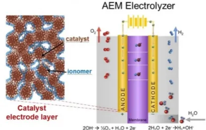
19
Water electrolysis utilizing a solid polymer electrolyte membrane has been widely studied.1
20
Compared to traditional alkaline water electrolysis that employs porous diaphragm separators with
21
alkaline solution electrolytes, solid polymer electrolytes provide advantages such as lower gas
22
crossover, improved efficiency, differential pressure operation, and improved operation dynamics.2
23
Two types of solid polymer electrolytes are currently being pursued: proton exchange membranes
24
(PEMs) and anion exchange membranes (AEMs).3 PEM water electrolysis (PEMWE) has matured
25
considerably over the past decade, fulfilling many of the technical requirements for power-to-gas
26
energy storage from renewables.4,5 PEM electrolyzer technology still requires expensive catalysts
27
based on noble metals, e.g., iridium and platinum, high cost perfluorinated polymers membranes
28
such as Nafion.6
29
AEM water electrolysis (AEMWE) has the potential to become a cheaper alternative to PEM
30
water electrolysis systems, for example by allowing for the use of non-precious transition metal
31
electrocatalysts.7 Therefore, AEM water electrolysis aims to combine the low costs of alkaline
32
electrolysis with the high power and flexibility of PEM electrolyzers.2 However, the water splitting
33
performance of AEM water electrolysis is currently much lower than that of PEMWE.8
34
In general, the membrane electrode assembly (MEA) consists of a polymeric membrane with
35
an anode and a cathode catalyst on each side of the membrane as shown in Fig 1. The catalyst can be
36
coated on the membrane, thus forming a catalyst-coated membrane (CCM). Alternatively, catalyst
37
ink can be coated on the porous substrate and compressed onto either side a polymer membrane
38
forming catalyst-coated substrates (CCS).9 In AEM water electrolysis, hydrogen gas and hydroxide
39
ions (OH−) produced from water reduction at the cathode while AEM exchanges (OH− ) ions to the
40
anode.10
41
42
2H2O 2H2 + O2 (1)
43
44
The overall reaction in equation (1) requires catalytic activity, towards the oxygen evolution
45
reaction (OER) at the anode and for the hydrogen evolution reaction (HER) at the cathode, to form
46
the respective gases from the electrode surfaces.11
47
The overall reaction requires a theoretical free energy electrolysis voltage or thermodynamic cell
48
voltage of 1.23 V to split water into hydrogen and oxygen at 25 oC.12
49
In practice, the cell voltage needed for efficient hydrogen generation must be higher than 1.23
50
V. Additional voltage is required to overcome over-voltages associated with electrode kinetics and
51
the ohmic resistance of the electrolyte and electrolyzers components, among others.2,13
52
53
Fig 1. Catalyst electrode layer and membrane electrode assembly for AEM electrolyzer, where the
54
catalyst is mixed with an ionomer, Reprinted from Artyushkova et al., License Number
55
4406040674790.14.
56
Performance improvement through the development of new materials and optimization of the
57
MEA fabrication process is of high importance. AEMs with high ionic conductivity and stability, as
58
well as catalysts with improved activity and durability in alkaline conditions have been studied in
59
various reports in recent years.3,15,16 An et.al.17 developed a mathematical model to predict the
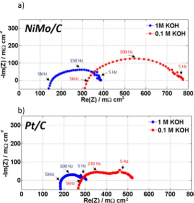
60
performance of AEMWE. Their results showed that an activation polarization of the hydrogen and
61
oxygen evolution reactions is responsible for the performance reduction (voltage to achieve specific
62
current) in AEMWE. This points to the necessity of developing high-performance MEAs through
63
electrocatalyst and membrane optimization.17,18
64
Only a few studies address the influence of a non-precious metal catalyst cathode and hydroxide
65
ion-conductivity in AEMWE devices. For example, Scott et al. 19,20 investigated the performance of
66
AEMWEs using different cobalt based oxides (2.5 – 3.0 mg cm-2) as the OER catalyst and Ni (2.0 mg
67
cm-2) as the HER catalyst. At a 1.9 V cell voltage, the cell achieved current densities ranging from 65
68
mA cm−2 (3.0 mg cm-2 of Cu0.7Co2.3O4) to 175 mA cm−2 (2.5 mg cm−2 of Li-doped Co3O4). Comotti et
69
al.20 demonstrated the effect of HER catalyst (Ni/(CeO2-La2O3)/C) loading on AEMWE performance,
70
the current density at 1.9 V increased from 160 to 470 mA cm−2 as the loading varied from 0.6 to 7.4
71
mg cm-2. Xiao et al. investigated high catalyst loadings for both the HER (NiMo 40 mg cm-2) and OER
72
(NiFe 40 mg cm-2) electrodes which resulted in AEMWE performance of 570 mA cm−2 at 1.9 V.21 This
73
performance was comparable to that observed using PGM catalysts for the HER (Pt, 3.2 mg cm-2),
74
and OER (IrO2, 2.9 mg cm-2) electrodes, respectively.1,21
75
2. Results and Discussion
76
In this paper we show that our synthesized NiMo catalyst offers a cathode performance
77
comparable to Pt nanoparticle catalyst in AEMWE. We also include a description of the influence of
78
the KOH concentration on the performance of NiMo HER catalysts in a real AEMWE environment.
79
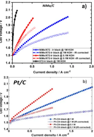
The NiMo catalyst was prepared by reducing an aqueous solution containing the Ni and Mo
80
metal precursors in presence of sodium borohydride. SEM images of the amorphous catalysts are
81
shown in Figs. S1 and S2 in electronic supplementary information (ESI†). The catalyst exhibited
82
nanosheet-like structures. These nanosheets are loosely stacked and form sponge-like structures,
83
leading to high specific surface areas. X-ray diffraction (XRD) indicates an amorphous nature of the
prepared catalyst as shown in Fig. S3 ESI†.22 Raman spectra reproduced in Fig. S4 ESI†, contain peaks
85
corresponding to the presence of one-phonon (1P) and two-photon (2P) NiO Raman modes at 570
86
and 1090 cm-1 respectively.23 The XPS spectrum in Fig. S5 ESI† of the NiMo nanosheets displays three
87
peaks at 230.6, 402 and 410 eV, related to Mo3d, Mo3p3/2, and Mo3p1/2 levels of molybdenum,
88
respectively. The NiMo nanosheets show peaks corresponding to the Ni2p3/2 and Ni2p1/2 levels, with
89
binding energies 854 and 873 eV respectively, and confirms the presence of NiO. A peak with a
90
binding energy of 187.0 eV corresponds to the of the B1S level of elemental boron. 24,25
91
The 25 cm2 AEM catalyst coated membranes (CCMs) were prepared by spraying (airbrush)
92
catalyst directly on to membranes mounted to a temperature controlled hot plate. Pt/C or NiMo
93
supported on Vulcan x72 carbon (NiMo/X72) were used as cathode catalysts while Ir black served as
94
the anode catalyst. Reinforced Fumatech membranes, Fumapem FAA-3-PE-30 and 10wt% Fumion
95
FAA-3-solute-10 ionomer in NMP were utilized in the MEA preparation. The MEAs (shown in Fig.
96
S6 in the ESI†) were assembled in a modified Baltic cell hardware between two commercially
97
available porous Ti transport layers for water electrolysis (Beakaert).TheMEAs were conditioned
98
and exchanged to the OH form in-situ.
99
The morphology of the catalyst layer is best described as catalyst particles covered with ionomer
100
and electrolyte as illustrated in Fig 1. Compositional uniformity along catalyst layers was confirmed
101
by energy dispersive X-ray (EDX) mapping as illustrated in Fig. S7 in the ESI†; the elemental mapping
102
shows a uniform distribution of Ni, Mo, O, and carbon. The cross-sectional interface view of the
103
cathode MEA demonstrated in Fig. S7 (ESI†) confirmed the uniform dispersion of the catalyst along
104
the MEA layer and its firm adherence to the membrane. SEM images (Fig. S8, ESI†) show that the
105
distribution of catalyst is also uniform across the surface of the AEM; the SEM images revealed no
106
voids or cracks in the catalyst layer.
107
The water electrolyzer setup consisted of a 5 L Teflon tank with heaters and a peristaltic pump,
108
which was used to pump hot KOH (50 oC) through the AEMWE cell. The cells were always filled
109
with the KOH solution during operation and were not exposed to ambient air. This eliminates some
110
of the drawbacks associated with AEM in fuel cells, e.g., membrane degradation due to dry
111
conditions and precipitation of carbonates. The ESI† provides more details on the preparation and
112
testing of the AEMWE cell.
113
Electrochemical impedance spectroscopy (EIS) was conducted to separate the ohmic resistance
114
from other contributions to the voltage of the AEMWE cells. Fig. 2 shows the impedance-plane plot
115
at 0.4 A cm-2 for the cells with NiMo/X72 cathodes (Fig.2 a) and Pt/C cathodes (Fig.2 b) for both 0.1
116
and 1.0 M KOH. The impedance-plane plots appear to consist of two partly overlapping and
117
depressed semicircles. (A high-frequency tail extending towards positive imaginary parts is
118
considered to be due to the electronics and the experimental setup and is not considered further in
119
this work). The low-frequency arcs are of similar size for the two catalysts, whereas the
high-120
frequency arc has a significantly larger radius for the NiMo catalyst than for Pt.
121
The total ohmic resistance of the 25 cm2 cell was determined from the high-frequency resistance
122
(HFR), i.e., from the intercept with the real (Re) axes of the impedance-plane plot. For 1 M KOH,
123
NiMo/X72 cell has an HFR of approximately 0.150 Ω cm2, which is lower compared to the Pt/C based
124
AEMWE cell (0.190 Ω cm2) and previously reported by Cho et al.8 This shows that despite having
125
higher NiMo loadings resulting in thicker catalyst layers, the NiMo/X72 cell still shows excellent cell
126
conductivity. However, a considerable increase in the HFR was observed when changing the KOH
127
concentration to 0.1 M KOH; 0.310 Ω cm2 for NiMo/X72 and 0.290 Ω cm2 for Pt/C. This HFR increase
128
at the lower KOH concentration may indicate insufficient ionic conductivity of the membrane.26 The
129
conductivity of the membrane is directly proportional to KOH concentration until reaches 5M KOH.
130
Beyond this concentration, the membrane conductivity tends to decrease as KOH concentration
131
increases.26 The differences in the HFR between the two catalysts may be attributed to constriction
132
134
Fig 2. Electrochemical impedance taken at 0.4 A in both 1M and 0.1M KOH at 50 oC. a) 5 mg cm-2
135
NiMo loading compared to b) 1 mg cm-2 Pt. Cell active area: 25 cm-2. Both CCMs using 3 mg cm-2
Ir-136
black.
137
We emphasize that apart from the cathode catalyst layers, the two cells were constructed using
138
the same components, i.e., using the same type of bipolar plates, porous transport layers, anode
139
catalyst layers, and membranes. Therefore, the differences in the EIS of the different cells are
140
attributed to the cathode catalyst layer only.
141
The low-frequency arc at around 5 Hz (Fig. 2) being of similar magnitude in the two cases, may
142
be attributed to mass transport8,28,29 or the anode30. The much larger high-frequency arc, on the other
143
hand, indicates significant differences in the kinetic contributions to the cell voltage from the
144
NiMo/X72 and Pt/C cathodes. For analysis, we converted the recorded impedance data to Tafel
145
impedance33, i.e., the impedance multiplied with the steady-state current density at which it was
146
obtained. For a kinetically limited process, the Tafel slope for the reaction can be found from the Tafel
147
impedance as the diameter of the impedance arc.30,31 Assuming that the entire impedance consists of
148
kinetic contributions in Fig. 2, we thus estimate the Tafel slope in 1 M KOH to be 50 mV for Pt and 95
149
mV for NiMo (Table S1 ESI†) at 0.4 A cm-2. Even if the low-frequency arc may be due to other
150
processes than that can be ascribed to the HER at the cathode, Fig. 2, and (Fig. S9, Fig. S10, ESI†)
151
indicates that the Tafel slope for the NiMo cell is twice that of Pt under the same process conditions.
152
Thus, the reaction mechanism is different at NiMo cell than at Pt cell.
153
Fig 3 shows the polarisation curves of both iR-corrected and uncorrected voltages for the
154
AEMWE at different KOH concentration, both for cells with cathode MEAs containing NiMo/X72
155
and Pt/C. For the polarisation curves that were corrected for ohmic resistance we used the following
156
equation:
157
ViR = V – (iRA) (2)
158
where ViR is the potential corrected for resistance; i is the current density in units of A cm-2; A is the
159
geometric area of the AEMWEs in cm2, and R is the area specific resistance measured by impedance
160
and in the units of Ω cm2. The current-voltage characteristics for the NiMo cells appear to be more
161
curved than those for the Pt cells, both for the iR-corrected and uncorrected data. Also, the slopes of
162
the iV-curves are larger for the cells with NiMo than those with Pt, in line with Tafel slopes from the
163
impedance measurements.
165
Fig 3. Polarisation curves in both 1M and 0.1M KOH at 50 oC. a) 5 mg cm-2 NiMo loading compared
166
to b) 1 mg cm-2 Pt. Cell active area: 25 cm-2. Both CCMs using 3 mg cm-2 Ir-black.
167
On the other hand, low KOH concentrations (< 1 M) does have a more adverse effect for the
168
NiMo cell than for the Pt cell. The activity decrease in 0.1 M KOH could be related to membrane
169
conductivity which decreases at lower KOH concentrations.26 The different reaction mechanisms
170
implied by the differences in Tafel impedance also suggest that the mechanisms and the reaction
171
orders are different at the two cathodes. A contribution to the pH dependence on the overall cell
172
performance from the cathode should therefore also be expected, as is rather clearly demonstrated in
173
Fig. 3.
174
Despite higher slightly onset potentials for NiMo/X72 compared to Pt/C, the NiMo cell displays
175
an excellent performance (Fig. 3), being comparable to that of the cell with the Pt cathode, achieving
176
1 A cm-2 at 1.9 V in 1 M KOH. The corresponding performance for the Pt cell is 1 A cm-2 at 1.8 V in 1
177
M KOH. In 0.1 M KOH, the difference was larger, the NiMo cell yielding 0.5 A cm-2 at 2V and the Pt
178
cell the same current at 1.65 V. The excellent performance of 1 A cm-2 at 1.75 V (iR-corrected) in 1 M
179
KOH obtained for the NiMo/X72 hydrogen catalyst outperforms all of those summarized in Table S2
180
ESI†. Nowadays commercial alkaline electrolyzers reach current densities up to 0.45 A cm-2 at a cell
181
voltage of 1.7–2.1 V, corresponding to a theoretical hydrogen generation rate of 1.9 Nm3 per m3 of the
182
cell area.18 Therefore NiMo/X72 catalyst potentially allows for low loading transition metal loading
183
in AEMWE operation on a commercial scale.18,32
184
3. Materials and Methods
185
3.1. Chemicals and materials
186
NiMo/X72 prepared in our lab, Commercial Pt/C (Alfa Aesar 60% on carbon support) and Ir
187
black (Alfa Aesar 99.8% S.A> 20 m2/g), Fumatech ionomer: Fumion FAA-3-SOLUT-10 anion exchange
188
polymer solution N-methyl-2-pyrrolidone (NMP) solvent solution, concentration 10 wt% purchased
189
from Fumatech BWT group, Germany.
190
Fumapem FAA 3 – PE membrane: Anion exchange Membrane (20-30 µm) purchased from
191
Fumatech BWT group, Germany. Sigma Aldrich supplied reagent grade Isopropanol (IPA). All
192
chemicals were used as received and deionized (D.I) water used was of 18.2 MΩ.cm resistivity.
193
NiMo Catalyst Synthesis: NiMo nanosheet prepared by reducing the aqueous mixture of
194
Ammonium molybdate tetrahydrate (NH4)6Mo7O24·4H2O and nickel nitrate hexahydrate Ni
195
(NO3)2·6H2O in the presence of sodium borohydride NaBH4 to produce Ni0.9Mo10 . The amorphous
196
NiMo supported on Vulcan carbon X72 (60wt%).
3.2. Catalyst characterization
198
The morphology of the NiMo nanosheets was studied Using scanning electron microscopy
199
(SEM, Carl Zeiss supra 55). NiMo nanosheets were investigated using Hitachi s-5500 FESEM, using
200
STEM mode, NiMo dissolved in ethanol and the solution deposited on Formvar/Carbon 300 mesh,
201
Copper grid hole size: 63µm. Structural and crystalline characteristics of the nanosheets were
202
investigated using a Bruker D8 A25 DaVinci X-ray Diffractometer with CuKα radiation. The average
203
wavelength of the radiation was 1.5425 Å. Raman spectroscopy was carried out with a Renishaw
204
InVia-Reflex Spectrometer using VIS excitation at 532 nm (100mW) with spectral resolution<1 cm-1.
205
Surface electronic states and composition of NiMo nanosheets were carried out by X-ray
206
photoelectron spectroscopy (XPS). XPS spectra were collected within an Axis Ultra DLD instrument
207
(Kratos Analytical) equipped with a monochromatic Al X-ray source.
208
3.3. MEA preparation
209
Ink preparation: the mixing procedure includes: 1) add required amount of water (4.8 gm) and
210
ionomer (1.92 gm) to catalyst powder then sonicate with ice for 15 minutes. 2) add IPA (4.8 gm). 3)
211
sonicate for 10 minutes with ice. 4)Mix with an ultrasonic probe for 5 minutes with ice, amplitude =
212
40%. For these experiments, we keep NiMo/X72 loading 5 mg/cm2 and Ir loading 3mg/cm2.
213
Spraying MEA: 25 cm2 MEA was done by airbrush spraying at 60 oC, a slower rate of spraying
214
resulted in better CCM. The MEAs were fabricated using airbrush spraying. The fumatech membrane
215
was assembled in a plastic holder that functions as a mask as well to leave only the active area open
216
to deposition. A commercial Coltech airbrush spraying (0.35 mm nozzle) was used during the
217
deposition. Wait 10 minutes between cathode and anode spraying.
218
3.3. Cell testing
219
For single cell tests: The MEAs were assembled in a modified Baltic cell hardware between two
220
commercially available Ti porous transport layer for water electrolysis (Beakaert). The MEA was
221
conditioned and exchanged to the OH form in-situ. The setup consists of 5 L Teflon tank with heaters
222
and a peristaltic pump to pump hot KOH through the AEMWE cell. The cell was operated at 50 °C
223
and atmospheric pressure, KOH was fed in anode and cathode sides. During cell testing, MEA with
224
carbon only as a cathode was used to evaluate the activity of the cell without NiMo catalyst.
225
For electrochemical analyses, a high-current potentiostat (HCP-803, Bio-Logic) was used to
226
control cell voltage and measure impedance. The current density was measured for repeated voltage
227
cycles from 1.5 to 2 V. Electrochemical impedance spectroscopy (EIS) was employed to determine the
228
cell performance–affecting resistances for different operating and electrode fabrication conditions,
229
with the corresponding analyses performed at different current densities such as 0.1, 0.4, and 0.8
230
A/cm2 in the AC frequency range of 50 kHz–200 mHz.
231
3.4. SEM and EDX mapping
232
The catalyst layers on the MEA and the cross-sectional view were examined by high-resolution
233
scanning electron microscopy (SEM); Zeiss supra 55 was used. Samples were prepared by cutting 1.0
234
mm wide strips from the different MEA and fixed on aluminum holders before analysis.
235
4. Conclusions
236
In summary, we have demonstrated that the use of amorphous NiMo catalyst supported on
237
carbon as cathode leads to AEM water electrolysis cell achieving 1 A cm-2 at 1.75 V (iR-corrected) in
238
1 M KOH supporting electrolyte. This shows that the performance of AEM water electrolysis may be
239
achieved at levels (especially on a cost vs. current basis) of significant commercial interest.
240
Supplementary Materials: The following are available online, Fig S1: a) SEM image of NiMo nanosheets, Fig S2
241
a) Inverted dark field STEM NiMo nanosheets b) NiMo supported in Vulcan x72 prepared by chemical
242
Fig S5: XPS spectrum of NiMo nanosheets, Fig S6:photograph of an individual MEA, Fig S7: a) SEM image of
244
MEA cross-section, b) EDX mapping of MEA prepared by airbrush spraying, and individual elemental mapping
245
for Ni, Mo, O, and C respectively, Fig S8: a) SEM image of NiMo/x72 cathode surface in MEA, b) SEM image of
246
Ir anode surface in MEA prepared by airbrush spraying, Fig S9: Tafel analysis of a) NiMo/X72 cell and b) Pt/C
247
cell in 1 and 0.1 M KOH, Fig S10: Tafel impedance analysis of a) and b) NiMo/X72 cell in 0.1 M and 1 M KOH
248
respectively, c) and d) Pt/C cell in 0.1 and 1 M KOH respectively, Table S1 Tafel impedance of NiMo/X72 cell
249
and Pt/C cell in 0.1 and 1M KOH at different current density, Table S2 Review of AEM water electrolysis
250
performance and development.
251
Author Contributions: Synthesis, electrochemical measurements, SEM, STEM, XRD, Raman, XPS data analysis,
252
writing and editing, Alaa Y. Faid; In-situ electrolysis testing, Funding acquisition, supervision, review and
253
editing, Alejandro Barnett; Supervision, funding acquisition, review and editing, Frode Seland; Funding
254
acquisition, supervision, review and editing, Svein Sunde.
255
Acknowledgments: Financially support from the Research Council of Norway, ENERGIX, HAPEEL, project
256
number 90218402, is greatly acknowledged. The Research Council of Norway is acknowledged for the support
257
to the Norwegian Micro- and Nano-Fabrication Facility, NorFab, project number 245963/F50.
258
Conflicts of Interest: “There are no conflicts to declare.”
259
References
260
1. Vincent, I., Kruger, A. & Bessarabov, D. Development of efficient membrane electrode assembly for low
261
cost hydrogen production by anion exchange membrane electrolysis. Int. J. Hydrogen Energy 42, 10752–
262
10761 (2017).
263
2. Leng, Y. et al. Solid-state water electrolysis with an alkaline membrane. J. Am. Chem. Soc. 134, 9054–9057
264
(2012).
265
3. Varcoe, J. R. et al. Anion-exchange membranes in electrochemical energy systems. Energy Environ. Sci. 7,
266
3135–3191 (2014).
267
4. Sapountzi, F. M., Gracia, J. M., Weststrate, C. J. (Kees-J., Fredriksson, H. O. A. & Niemantsverdriet, J. W.
268
(Hans). Electrocatalysts for the generation of hydrogen, oxygen and synthesis gas. Prog. Energy Combust.
269
Sci. 58, 1–35 (2017).
270
5. Grond, L., Schulze, P. & Holstein, J. Systems Analyses Power to Gas. DNV Kema GCS 13.R.2, 1–70 (2013).
271
6. Kuckshinrichs, W., Ketelaer, T. & Koj, J. C. Economic Analysis of Improved Alkaline Water Electrolysis.
272
Front. Energy Res. 5, (2017).
273
7. Gong, M., Wang, D. Y., Chen, C. C., Hwang, B. J. & Dai, H. A mini review on nickel-based electrocatalysts
274
for alkaline hydrogen evolution reaction. Nano Res. 9, 28–46 (2016).
275
8. Kyung, M. et al. Factors in electrode fabrication for performance enhancement of anion exchange
276
membrane water electrolysis. J. Power Sources 347, 283–290 (2017).
277
9. Phillips, R. & Dunnill, C. W. Zero gap alkaline electrolysis cell design for renewable energy storage as
278
hydrogen gas. RSC Adv. 6, 100643–100651 (2016).
279
10. Xiang, C., Papadantonakis, K. M. & Lewis, N. S. Principles and implementations of electrolysis systems
280
for water splitting. Mater. Horiz. 3, 169–173 (2016).
281
11. Eftekhari, A. Electrocatalysts for hydrogen evolution reaction. Int. J. Hydrog. Energy 42, 11053–11077
282
(2017).
283
12. Li, X., Hao, X., Abudula, A. & Guan, G. Nanostructured catalysts for electrochemical water splitting:
284
current state and prospects. J. Mater. Chem. A 4, 11973–12000 (2016).
285
13. Bladergroen, B., Su, H., Pasupathi, S. & Linkov, V. Overview of Membrane Electrode Assembly
286
Preparation Methods for Solid Polymer Electrolyte Electrolyzer. in Electrolysis (Intech, 2012).
287
14. Artyushkova, K. et al. Application of X-ray photoelectron spectroscopy to studies of electrodes in fuel
289
cells and electrolyzers. J. Electron Spectros. Relat. Phenom. (2017). doi:10.1016/j.elspec.2017.12.006
290
15. Cho, M. K. et al. Alkaline anion exchange membrane water electrolysis: Effects of electrolyte feed method
291
and electrode binder content. J. Power Sources 382, 22–29 (2018).
292
16. Sassin, M. B., Garsany, Y., Gould, B. D. & Swider-Lyons, K. E. Fabrication Method for Laboratory-Scale
293
High-Performance Membrane Electrode Assemblies for Fuel Cells. Anal. Chem. 89, 511–518 (2017).
294
17. An, L., Zhao, T. S., Chai, Z. H., Tan, P. & Zeng, L. Mathematical modeling of an anion-exchange
295
membrane water electrolyzer for hydrogen production. Int. J. Hydrog. Energy 39, 19869–19876 (2014).
296
18. Buttler, A. & Spliethoff, H. Current status of water electrolysis for energy storage, grid balancing and
297
sector coupling via power-to-gas and power-to-liquids: A review. Renew. Sustain. Energy Rev. 82, 2440–
298
2454 (2018).
299
19. Wu, X. & Scott, K. A non-precious metal bifunctional oxygen electrode for alkaline anion exchange
300
membrane cells. J. Power Sources 206, 14–19 (2012).
301
20. Pavel, C. C. et al. Highly efficient platinum group metal free based membrane-electrode assembly for
302
anion exchange membrane water electrolysis. Angew. Chemie - Int. Ed. 53, 1378–1381 (2014).
303
21. Xiao, L. et al. First implementation of alkaline polymer electrolyte water electrolysis working only with
304
pure water. Energy Environ. Sci. 5, 7869–7871 (2012).
305
22. Nie, M., Zou, Y. C., Huang, Y. M. & Wang, J. Q. Ni-Fe-B catalysts for NaBH4hydrolysis. Int. J. Hydrog.
306
Energy 37, 1568–1576 (2012).
307
23. Mironova-Ulmane, N. et al. Raman scattering in nanosized nickel oxide NiO. J. Phys. Conf. Ser. 93, (2007).
308
24. Gupta, S. et al. Co-Mo-B Nanoparticles as a non-precious and efficient Bifunctional Electrocatalyst for
309
Hydrogen and Oxygen Evolution. Electrochim. Acta 232, 64–71 (2017).
310
25. Gupta, S. et al. Co-Ni-B nanocatalyst for efficient hydrogen evolution reaction in wide pH range. Appl.
311
Catal. B Environ. 192, 126–133 (2016).
312
26. Kraglund, M. R. et al. Zero-Gap Alkaline Water Electrolysis Using Ion-Solvating Polymer Electrolyte
313
Membranes at Reduced KOH Concentrations. J. Electrochem. Soc. 163, F3125–F3131 (2016).
314
27. Fleig, J. The Influence of Current Constriction on the Impedance of Polarizable Electrodes. J. Electrochem.
315
Soc. 144, L302 (1997).
316
28. Dedigama, I. et al. In situ diagnostic techniques for characterisation of polymer electrolyte membrane
317
water electrolysers - Flow visualisation and electrochemical impedance spectroscopy. Int. J. Hydrogen
318
Energy 39, 4468–4482 (2014).
319
29. Sun, S., Shao, Z., Yu, H., Li, G. & Yi, B. Investigations on degradation of the long-term proton exchange
320
membrane water electrolysis stack. J. Power Sources 267, 515–520 (2014).
321
30. Jaouen, F., Lindbergh, G. & Wiezell, K. Transient Techniques for Investigating Mass-Transport
322
Limitations in Gas Diffusion Electrodes. J. Electrochem. Soc. 150, A1711 (2003).
323
31. Darab, M., Barnett, A. O., Lindbergh, G., Thomassen, M. S. & Sunde, S. The Influence of Catalyst Layer
324
Thickness on the Performance and Degradation of PEM Fuel Cell Cathodes with Constant Catalyst
325
Loading. Electrochim. Acta 232, 505–516 (2017).
326
32. Vincent, I. & Bessarabov, D. Low cost hydrogen production by anion exchange membrane electrolysis: