\
MARKSMAN DISK DRIVE
TECHNICAL MANUAL
MARCH 1979
PUBLICATIONS RECORD "
REVISION NOTES
CONTENTS
Section . Page
1 GENERAL INFORMATION ... '" ... '" ... 1-1 Scope and Organization of Manual ... 1-1 General Description . . . 1-1 Specifications . . . .. 1-1 Options ... , 1-1
2 INSTALLATION AND OPERATION ... 2-1 Unpacking and Inspection ... , ... 2-1 Unpacking and Handling ... 2-1 Equipment Inspection ... : ... 2-1 Installation Check List ... : ... 2-1 Electromechanical Checks (Optional) ... 2-3 Ac Power Connection ... 2-3 Dc Voltage Connections ... 2-4 Grounding ... 2-4 Offline Operational Checkout (Optional) ... 2-4 Signal Cables and Cable Fabrication ... 2-5 Installation ... 2-5 Write Clock Phase Selection ... 2-5 Fixed Length Sectoring . . . 2-6 Online Operation ... 2-6 Operation ... 2-6 Format Definitions ... 2-6 Sector Calculations ... 2-6 Interface Signals ... 2-7 Interface Description ... 2-7 General ... 2- 7 One Byte Commands ... 2-7 Head Advance ... 2-7 Rezero ... 2-9 Request Status ... 2-9 Normal Status ... 2-9 Expanded Status ... 2-16 Two Byte Commands ... 2-16 Diagnose (Optional) ... 2-16 Data Transfer ... .' .. : ... 2-16 Reading ... 2-17 Non- Imbedded ID Field ... 2-17 Imbedded ID Field ... 2-17 Writing ... , ... , .. , ... 2-17 Non- Imbedded ID Field ... 2-17 Imbedded ID Field ... 2-17 Error Handling ... 2-17
3 THEORY OF OPERATION ... 3-1 General . . . .. 3-1 Disk and R/W Head Configuration ... 3-2 Disk Zones and R/W Head Positioning ... 3-2 Drive Control ... 3-3 On and Initialization Sequence ... 3-4
CONTENTS (Continued)
Section Page
Sequence-Up Operation ... '.' ... 3-4 Seek Operation ... : ... 3-5 Rezero Operation ... 3-5 Head Advance Operation ... 3~5 Set Sector Operation . . . 3-5 Diagnostic Operation ... 3-5 Request Status Operation ... 3-5 Data Recording Method . . . 3-6 Write Data Recording ... , ... 3-6 Read Data Recovery ... 3-7 Fixed Length Sectoring ... " 3-8 Write Protect ... " 3-8
4 OPTIONS ... , ... 4-1 'Driver/Receiver II' Interface PCB ... 4-1 Dc Power Supply ... 4-1 Enclosure and Ac Distribution ... 4-1 Rack Mount Slides ... ~ ... 4-1 V.D.E. Safety Requirements ... 4-1 Color Options ... 4-1 Power Conversion ... 4-7
Interface Conversion ... 4-7 Altitude Conversion ... 4-7
V.D.E. Conversion ... 4-7
5 MAINTENANCE ... 5-1 Basic Drive Control II PCB Replacement ... 5-1 Drive Motor Assembly Replacement ... 5-1 Drive Motor PuIIey Replacement ... 5-2 '
Brake Assembly Replacement ... 5-3 Index and Clock Transducer Replacement ... 5-4 Spindle Grounding Spring ... 5-5 Drive Belt Replacement ... ',' ... 5-6 Relay Control Assembly and Component Replacement ... 5-6 Sealed Drive Assembly Replacement ... 5-6 Maintenance Aids, ... 5-7 Power-Sequencing Malfunctions ... 5-8 Read/Write Malfunctions ... , ... 5-8 Spindle Malfunctions ... " .. : ... 5-9 Interface Malfunctions . . . 5-9 Positioning Malfunctions ... ~ .. : . . . .. 5-9
6 ILLUSTRATED PARTS BREAKDOWN ... 6-1 Purpose ... '" ... 6-1 Section Usage . . . 6-1 Group Assembly Parts List ... 6-1'
Figure 2-1 2-2 2-3 2-4 2-5 2-6 2-7 2-8 2-9 2-10 2-11 2-12 2-13 2-14 2-15 2-16 2-17 2-18 2-19 2-20 3-1 3-2 3-3 3-4 3-5 3-6 3-7 3-8 3-9 4-1 5-1 5-2 5-3 5-4 5-5 5-6 5-7 5-8 6-1 6-2 6-3 6-4 ILLUSTRATIONS Page
Marksman Disk Drive (Top View) ... 2-2 Marksman Disk Drive (Bottom View) ... 2-2 AC Power Connection ... 2-4 DC Voltage Connections ... ' .. 2-4 Grounding ... ;... 2-5 Write Clock Phasing. " ... 2-6 Sector Formats ... 2-6 Number of Sectors per Track ... 2-7 Net Capacity M-20 ... 2-7. One Byte Commands (Except head advance) Flow Diagram ... 2-10 One Byte Commands (Except head advance) Timing ... 2-11 One Byte Head Advance Command Flow Diagram ...•... 2-12 One Byte Head Advance Command Timing ... 2-13 Two Byte Commands Flow Diagram ... 2-14 Two Byte Commands Timing ... 2-15 Media Initialization ... 2-16 Non-Imbedded ID Field Read Timing ... 2-17 Imbedded ID Field Read Timing ... 2-18 Non-Imbedded ID Field Write Timing ... , ... 2-18 Imbedded ID Field Write Timing ... " ... , ... 2-18 Marksman Disk Drive Functional Block ... 3-1 R/W Head Configuration ... 3-2 Disk Zones ... ' . . . . .. 3-3 Program Flow Diagram ... 3-3 Drive Control Block Diagram ... 3-4 Code Format Comparisons and TFM Characteristics ... 3-6 Write Data System Block Diagram ... 3-7 Read Data System Block Diagram ... 3-7 Read Data Detection ... 3-9 Driver/Receiver II Logic Diagram ... 4-2 Basic Drive Control II Printed Circuit Board ... 5-1 Drive Motor Assembly ... 5-2 Brake Assembly ... 5-3 Brake Adjustment Jumper Location ... 5-4 Index/Clock Transducer Assembly ... 5-5 Grounding Spring Assembly ... 5-5 Drive Belt Tension ... 5-6 Control Relay Assembly ... 5-7 Marksman Disk Drive Unit ... ' ... ~ ... 6-3 Basic Control II Board Assembly VR106 ... 6-4 Wired Drive Assembly ... 6-5 Control Relay Assembly ... " ... .' ... 6-7
TABLES
Table Page
1-1 Marksman Specifications ... ~ ... " ... ',i' • . • ..•••• 1-2 2-1 Installation Check List ... " ... ',' ... "".\. ...• 2-3 2-2 40 Pin Flat Cable Assembly Pin Assignments ...•...•... 2-5 2-3 Control Signals ... 2-8 2-4 Read/Write Signals ...•... ':' ... . 'i' .•••••• '2-9
SECTION 1
GENERAL INFORMATION
SCOPE AND ORGANIZATION OF MANUAL
This manual contains information pertaining to the in-stallation, operation, and maintenance of the Marksman Disk Drive. This manual is divided into six sections:
• Section 1 - General Information • Section 2 - Installation and Operation • Section 3 - Theory of Operation • Section 4 - Options
• Section 5 - Maintenance
• Section 6 - Illustrated Parts Breakdown
GENERAL DESCRIPTION
The Marksman Disk Drive is a fixed media mass memory device used for data storage in a data processing system. The Marksman uses fourth generation technol-ogy for high performance and floppy disk techniques for maximum economy. Data integrity comparable to that found. in large disk systems is assured by the use of Win-chester heads and media.
System reliability is maximized by a sealed, contamina-tion controlled disk area and the reduccontamina-tion in the parts count achievable by the use of a microprocessor. The Marksman stores data on both sides of a single disk us-ing two movus-ing heads per surface providus-ing a maximum memory capacity of 20.16 megabytes.
The Marksman uses a fixed mechanical timing wheel at-tached to the rotating disk and a Phase Lock Oscillator (PLO) to establish the basic synchronization between disk position and all drive control and recording func-tions. The Marksman provides programmable sector recording format and uses Double Density (TFM) data encoding techniques.
Head positioning is provided by a split band-stepper motor mechanism whose performance is improved by the microprocessor allowing higher speed slew capabilities.
The basic Marksman Disk Drive includes sealed disk assembly with drive motor and stepper assembly and one circuit board for minimal drive control functions.
The complete linear read/write circuitry including a data separator function are part of the basic control circuit board.
SPECIFICATIONS
Table 1-1 lists the operating specifications for the Marks-man Disk Drive.
OPTIONS
· Century Data Systems provides five options· i for the basic Marksman Disk Drive:
• Receiver/Drive Interface Board • DC Power Supply
• Enclosure and AC Distribution • Rack Mount Slides
• VDE Safety Requirements
Tracks per Cylinder Number of Cylinders Bytes per Track Bytes per Cylinder Bytes per Drive Track Density Recording Density
Minimum Positioning Time
Maximum Positioning . Time
Average Positioning Time Head Settling Time Rotational Speed Maximum Latency Time Average Latency Time Recording Method
Data Transfer Rate Bit Cell Time
Drive Sequence Up Time
Sequence Up Read Time Sequence Up Write Time AC Input Power
Starting Current Running Current DC Power
TABLE 1·1. MARKSMAN SPECIFICATIONS
4
Physical Dimensions213 Basic Drive (dimensions
24,000 exclude all qptions)
96,000 Width
20.16 million
182 tracks per inch Depth
7,545 bits per inch,
nominal Height
3 milliseconds
Operating Weight
113 milliseconds Shipping Weight
With Options (dimensions 43 milliseconds include optional enclosure, 17 milliseconds and power supply)
2,400 rpm ±4 percent Width
26 milliseconds Depth
12.5 milliseconds
Bit serial Triple Prequency Height Modulation (TPM)
960,000 bytes per second Operating Weight 130 nanoseconds
3 minutes (Start to Drive Shipping Weight
Ready) Ambient Limits
3 minutes Temperature
3 minutes
115 Volts rms (+10%, -15%)
50/60 Hertz (±1 Hz.) Humidity
Single Phase
11 amperes Altitude
1.5 amperes
+24 Volts ±5% at 2.7 amperes
-12 Volts ±5% at 0.3 amperes
+5 Volts ±5% at 2.5
amperes Heat Dissipation
Air Cooling (without enclosure)
16.5 inches (41.9 centi-meters)
21.5 inches (54.6 centi-meters)
8.5 inches (21.6 centi-meters)
45 pounds (20.4 kilograms) ,60 pounds (27.2 kilograms)
19 inches (48.3 centimters) 27.25 inches (69.2 centi-meters)
8.75 inches (22.2 centi-meters)
110 pounds (49.9 kilo-grams)
130 pounds (59 kilograms)
500P to 104°P (6.1 °C to'
(40°C) with maximum , gradient of 18°P (l0°C) per hour
10 to 90 percent, relative, without condensation 1,000 feet (0.3 kilometers) below sea level to 6,000 feet (1.8 kilometers) above sea level
With optional kit: extend range to 10,000 feet (3 kilometers) above sea level 650 BTU/Hour/Drive , (Basic Drive with no
inter-face board)
SECTION 2
INSTALLATION AND OPERATION
UNPACKING AND INSPECTION
Marksman Disk Drives are normally packed in a pre-formed styrofoam container which is placed in a corru-gated container for both domestic and overseas shipment and handling. These containers can be stacked. Ifthe ex-terior condition of the container indicates the likelihood of interior damage to the unit, unpacking should be car-ried out in the presence of the carrier or his agent where possible. In any case, units should be unpacked and checked for shipping damage as soon as received.
UNPACKING AND HANDLING
The following procedure is based upon current packing methods and is subject to possible minor changes. After inspecting the exterior of the container for obvious ship-ping damage, proceed as follows:
Note
The shipping weight of the unit is approxi-mately 60 pounds (27.2 kilograms). Care should be used in handling and moving.
1. Move the container to a suitable workbench.
Note
It may prove expedient to save all of the pack-ing material for possible reshipment.
2. Open the box enclosure, remove and retain any loose items and/or documentation from the top of the inner container.
3. Remove styrofoam inner container from box enclosure and place on workbench.
4. Cut shipping tape and lift top up and off styrofoam container.
S. Lift disk drive out of . styrofoam container and place on the workbench on its side with drive motor down (Figure 2-1).
6. Install four shipping legs to bottom of drive (Figure 2-2).
7. Set unit on all four shipping legs.
EQUIPMENT INSPECTION
Inspect the unit visually for evidence of rough handling during shipment, such as:
• Deformed frame members • Cracks or breaks in casting
• Cracks or breaks in top of sealed unit
• Cracked printed circuit board, particularly around mounting holes
• Loose or broken cable connectors • Loose or damaged drive motor pulley
• Bent or broken timing wheel and sensor assembly • Damaged spindle pulley
• Loose or damaged relay assembly • Drive belt loose or off pulleys
INSTALLATION CHECK LIST
An Installation Check List is provded, Table 2-1, follow-ed by the recommendfollow-ed procfollow-edures for preinstallation unit checkout, unit installation, and installation check-out prior to online use.
Note
The Installation Check List is for the use of experienced installation technicians. Other service personnel should follow the recom-. mended procedures.
Problems found during the preceding unit inspection must be corrected before proceeding further. If any ad-justments or parts replacement are required to put the disk drive online, be sure to note all corrective action taken on the Installation Completion Form.
DRIVE BEL T
DRivE MOTOR
P6 J2
Figure 2·1. Marksman Disk Drive (Top View)
SHIPPING LEG RELAY ASSEMBLY
Figure 2·2. Marksman Disk Drive (Bottom View)
Table 2-1. INSTALLATION CHECK LIST
VISUAL INSPECTION
o
Remove all packing materialo
Check for shipping damageo
Check all wiring and connectorsELECTROMECHANICAL CHECKS (OPTIONAL)
D. Check spindle grounding brush pressure and elec-trical resistance
AC POWER CONNECTION
o
Check for correct voltage and phaseo
Connect ac power cord to 11 on relay assemblyDC VOLTAGE CONNECTION
o
Connect dc power supply outputs to J2 on Basic Drive Control II pcbo
Check +24 volts ±S percento
Check +S volts ±S percento
Check -12 volts ±S percentGROUNDING
o
Controller to power supply groundingo
Logic ground from power supply to pcb grounding lugo
Ground strapping at power supplyELECTROMECHANICAL CHECKS (OPTIONAL) The following electromechanical checks are optional and need to be performed only if the unit was obviously drop-ped or subject to gross mishandling during shipment. Detailed procedures for making these checks and any necessary adjustments can be found in the' maintenance section.
1. Set unit on its side (drive motor down) and check spindle grounding brush pressure and electrical resistance.
2. Check spindle drive belt for proper centering and tension.
3. Check for any physical damage to pcb or sealed unit.
4. Set unit on all four shipping legs.
OFFLINE OPERATIONAL CHECKOUT (OPTIONAL)
o
Check spindle up/down operationo
Check positioningo
Check for index pulseso
Check for sector pulsesINTERFACE
o
Install interface pcbo
Connect signal ribbon cable to interface pcbINSTALLATION
o
Remove shipping legso
Mount unitSYSTEM CABLING
o
Install customer supplied signal and ground cablesONLINE OPERATION
o
Check write clock phasingo
Check unit sequencing and seek positioningo
Check unit for worst-casting data recoveryAC POWER CONNECTION CAUTION
The basic Marksman Disk Drive is not pro-tected by any ac line fuse or breaker; the user shall be responsible for all ac safety require-ments.
WARNING
Compare voltage andfrequency requirements from unit identification tag with available power. Connecting wrong voltage and/or fre-quency could damage the unit.
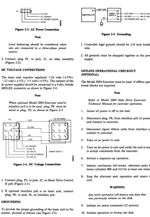
1. The unit end of the power cable should connect to a 4 pin, female MOLEX connector as shown in Figure
2-3.
Figure 2·3. AC Power Connection
Note
Load balancing should be considered when uits are connected to a three-phase power source.
2. Connect plug P1, to jack, H, on relay assembly (Figure 2-2).
DC VOLTAGE CONNECTIONS
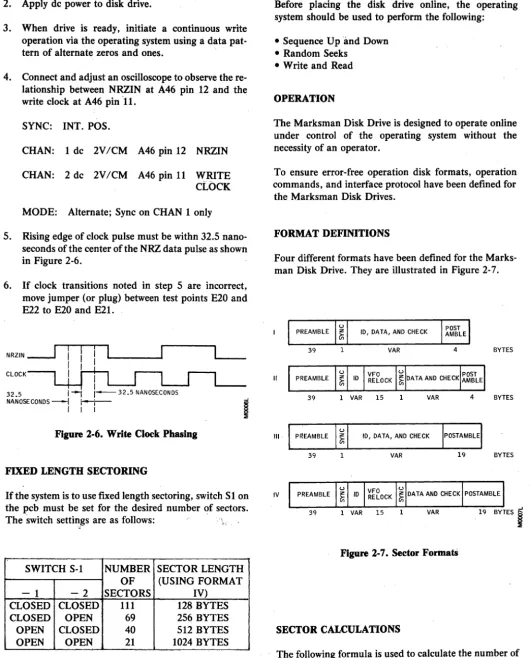
The basic unit requires regulated +24 volts (±S%), -12 volts (±S%), +5 volts (±S%). The outputs oftl:1e dc power supplies should be connected to a 9 pin, female MOLEX connector as shown in Figure 2-4.
90
Note
When optional Model 2004 Exerciser and/or interface pcb is to be used. plug. P6. must be wired to plug. P2. as shown in Figure 2-3.
P2 -12V
,..---
P6 OPTIONAL60
~
I
I 90 603!
DC GRD I8(>- 51, 2_ f -
I
I
80 50 2, <1 ~ I
4, IT <
7
4, +5V I 70 +l2V
I
I
1
I I I I I I I I I IL. _______ ~.
_oJ
'-- DC GROUND
}
'''"''
'"""
~+5VOLTS-12 VOL TS +24 VOL TS GROUND +24 VOL TS
Figure 2·4. DC Voltage Connections
,1. Connect plug, P2, to jack, J2, on Basic Drive Control II pcb (Figure 2·1).
2. If optional interface pcb is on basic unit, connect plug. P6, to jack, J6, on interface pcb.
GROUNDING
To provide the proper grounding of the basic unit to the system, proceed as follows (see Figure 2-5).
CONTROLLER +24V GRD--.~ P2 PIN 8 DC GRD --_~ P2 PIN 2
..-:-:c~--_>--I-- AC/CHASSIS GRD _ PI
Figure 2·5. Grounding
1. Controller logic ground should be 3/8 inch braided wire.
2. All grounds must be strapped together at the power supply.
OFFLINE OPERATIONAL CHECKOUT (OPTIONAL)
The Model 2004 Exerciser must be used, if offline opera-tional checks are required.
Note
Refer to Model 2004 Disk Drive Exerciser Technical Manual for exerciser operation.
1. Insure all power is offto the unit.
2. Disconnect plug, P6, from interface pcb (if present) and connect to exerciser.
3. Disconnect signal ribbon cable from interface and connect to exerciser.
4. Turn on ac power to unit.
S. Turn on dc power to unit and verify the unit is ready to accept commands from the exerciser.
6. Initiate a sequence-up operation.
7. Initiate continuous full-stroke, alternate seeks be-tween cylinders 000 and 212 for at least one minute.
8. Stop the alternate seek operation and rezero the unit.
WARNING
Any write operation will destroy any data that was perviously written on the disk.
9. Initiate set sector command (12 sectors).
11. Initiate continuous random seeks and read opera-tion for at least 5 minutes. Unit should run error free.
12. Stop random seek and read operation and rezero unit.
13. Using an oscilloscope, verify Index pulses occur ap-proximately every 25 milliseconds at chip A14, pin 9 on the Basic Control II board.
14. Using an oscilloscope, verify Sector pulses occur ap-proximately every 2.08 milliseconds at chip A4, pin
4.
15. Initiate a sequence-down operation, when disk has stopped, turn off ac and dc power to the unit.
16. Disconnect exerciser.
SIGNAL CABLES AND CABLE FABRICATION
The basic unit supplies all interfacing signals via a 4-inch pin flat cable assembly from the Basic Control II board. All signals require cable drivers/receivers before they can be connected to the system.
Pin assignments for the 40 pin flat cable assembly are shown in Table 2-2.
Note
Refer to the operation portion of this section for signal definitions.
INSTALLATION
The Marksman Disk Drive may be mounted in either a horizontal or vertical position.
Note
Refer to specifications in Section I for drive dimensions, weight, and air circulation re-quirements.
1. Remove the four shipping legs.
2. Install unit as desired.
3. Connect all power and system cables.
TABLE 2·2. 40 PIN FLAT CABLE ASSEMBLY PIN ASSIGNMENTS
Pin
No. Signal Name
1 CACK
2 RSTI
3 CBUS0
4 CBUS 1
5 SPARE
6 CREQ
7 GRD
8 CBUS 2
9 CBUS 6
10 CBUS 7
11 CBUS5
12 CBUS 3
13 SPARE
14 IDX
15 GRD
16 DRDY
17 CRDY
18 GRD
19 1 MHZ
20 GRD
21 SEC
22 GRD
23 CSTAT
24 GRD
25 WRTCLK
26 GRD
27 NRZIN
28 GRD
29 RDCLK
30 GRD
31 NRZOUT
32 GRD
33 WRTGATEI
34 GRD
35 RDGATE
36 SPARE
37 NRZ/MILLER CONTROL
38 SPARE
39 WRTUSF
40 CBUS 4
WRITE CLOCK PHASE SELECTION
This selection of write clock phase is done to compensate for delays in write data timing due to differences in cable lengths between the controller and the various drives. This must be done on each new disk drive when it is first installed in the system or when a disk drive is physically relocated within the system.
1. Apply ac power to disk drive.
2. Apply dc power to disk drive.
3. When drive is ready, initiate a continuous write operation via the operating system using a data pat-tern of alpat-ternate zeros and ones.
4. Connect and adjust an oscilloscope to observe the re-lationship between NRZIN at A46 pin 12 and the write clock at A46 pin 11. .
SYNC: INT. POS.
CHAN: 1 dc 2V/CM A46 pin 12 NRZIN
CHAN: 2 dc 2V/CM A46 pin 11 WRITE CLOCK
MODE: Alternate; Sync on CHAN 1 only
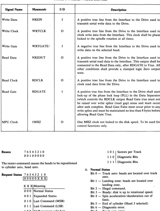
5. Rising edge of clock pulse must be withn 32.5 nano-seconds of the center of the NRZ data pulse as shown in Figure 2-6.
6. If clock transitions noted in step 5 are incorrect, move jumper (or plug) between test points E20 and E22 to E20 and E21.
NRZIN
---.J
CLOCKI I
32.5 I~ 1 - 3 2 . 5 NANOSECONDS
NANOSECONDS ---l r---t-- -I
I I I
i
Figure 2·6. Write Clock Phasing
FIXED LENGTH SECTORING
If the system is to use fixed length sectoring, switch Sl on the pcb must be set for the desired number of sectors. The switch settings are as follows: .,
"
SWITCH S-l NUMBER SECTOR LENGTH OF (USING FORMAT
- 1 - 2 SECTORS IV)
CLOSED CLOSED 111 128 BYTES
CLOSED OPEN 69 256 BYTES
OPEN CLOSED 40 512 BYTES
[image:15.623.44.575.73.731.2]OPEN OPEN 21 1024 BYTES
Figure 2-1. shows the location of switch S-l.
... ONLINE OPERATION
Before placing the disk drive online, the operating system should be used to perform the following:
• Sequence Up and Down • Random Seeks
• Write and Read
OPERATION
The Marksman Disk Drive is designed to operate online under control of the operating system without the necessity of an operator.
To ensure error-free operation disk formats, operation commands, and interface protocol have been defined for the Marksman Disk Drives.
FORMAT DEFINITIONS
Four different formats have been defined for the Marks-man Disk Drive. They are illustrated in Figure 2-7.
10, DATA, AND CHECK
39 1 VAR 4 BYTES
II
39 1 VAR 15 1 VAR 4 BYTES
III 10, DATA, AND CHECK
39 VAR 19 BYTES
IV
39 1 VAR 15 VAR 19 BYTES
I
Figure 2-7. Sector FormatS
SECTOR CALCULATIONS
N=
. Data+
2400 HDR - OHWhere:
N = number of sectors (round to next lower integer)
Data = length of·data field plus check characters
HRD = length of header
OH = 44 for Format 1
=:
60 for Format II = 59 for Format III = 75 for Format IVWhenever it is necessary to change heads at the end of a track and continue operation without losing a revolution, a 100 byte end of track pad must be assigned. In this case, the sector formula must be changed to:
N=
23900Data & HDR
+
OHFORMAT SECTOR SIZE
I II III IV
128 BYTES 129 119 119 111
256 BYTES 76 72 72 69
512 BYTES 42 41 41 40
1024 BYTES 22 21 21 21
MOOOBL
Figure 2-8. Number of Sectors per Track.
*
Assuming a 8 byte ID field and a 5 byte check character.FORMAT SECTOR SIZE
I II III IV
128 BYTES 13.87 12.79 12.79 11.93 256 BYTES 16.34 15.48 15.48 14.84 512 BYTES 18.06 17.63 17.63 17.20 1024 BYTES 18.92 18.06 18.06 18.06
MOOOBL
Figure 2-9. Net Capacity M-20**
**M-l0 capacity is one half of that shown.
INTERFACE SIGNALS
Signals appearing at the Marksman Disk Drive interface and their use are shown in Tables 2-3 and 2-4.
INTERFACE DESCRIPTION
General
The controller interface functions may be divided into four areas:
• Single Word Commands (Sequence, Rezero, Status, Advance Head)
• Two Word Commands (Seek, Set Sector, Diagnose) • Data Transfer Commands (Read, Write)
• Error Handling
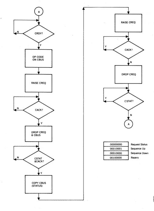
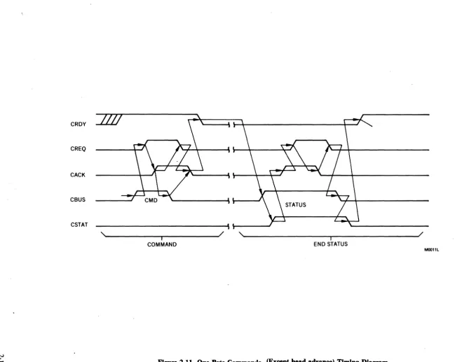
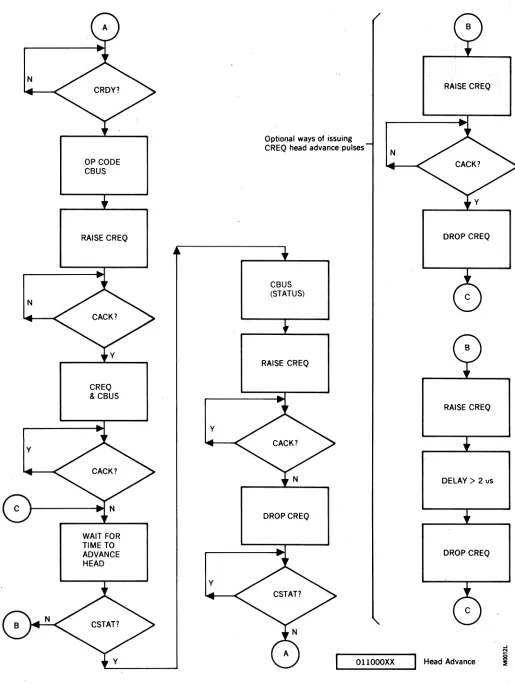
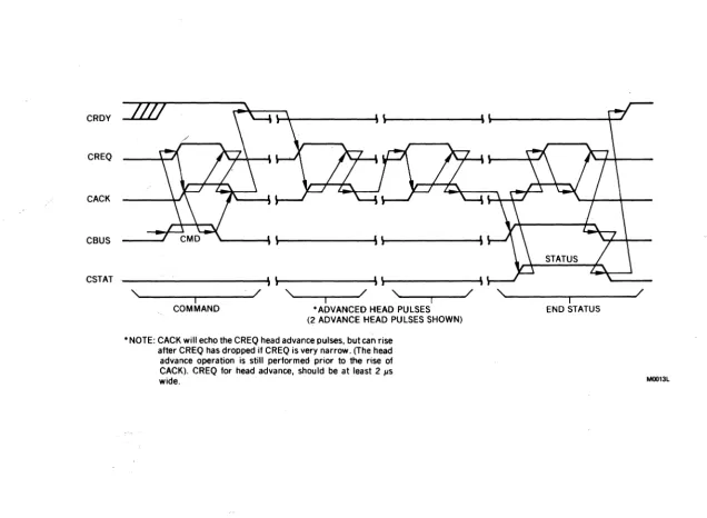
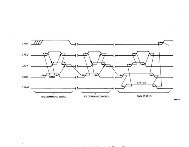
Figures 2-10 thru 2-13 are the flow charts and timing diagrams for one byte commands.
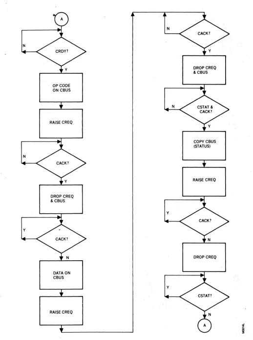
Figures 2-14 and 2-15 are the same for the two word commands.
One Byte Commands
Sequence . 7 6 5 4 3 2 1 0 10001000xi
Bit 0 = 0 Sequence Up Bit 0 = 1 Sequence Down
The sequence command causes the disk drive motor to power up (Bit 0 = 0) or power-down (Bit 0 = 1). During a power up, the speed of the disk is checked and when the rotational speed is within tolerance, the heads are positioned to cylinder zero, head zero. During a power down, the heads are positioned to the landing zone before power is removed from the drive motor.
Head Advance 7 6 5 4 3 2 1 0 1011000 X xl
X X Meaning
o
0 No Operationo
1 Head Advance one time 1 0 Head Advance two times1 1 Head Advance three times
The head advance command provides a means for rapid-ly advancing the head thereby allowing sequential sector access across head boundaries.
Signal Name
Control Bus
Control Request
Control Acknowledge
Control Ready
Control Status
Drive Ready
Drive Reset
Index
Sector
Write Unsafe
-. - -_. TABLE 2·3. CONTROL SIGNALS
Mnemonic
CBSO-7
CREQ
CACK
CRDY
CSTAS
DRDY
RST/
IDX
SEC
WRTUSF
I/O
Both
I
o
o
o
o
I
o
o
o
Description
A high active 8 bit wide bus used to transfer commands from the Interface and status to the Interface.
A high active line from the Interface, used in conjunction with the CACK line to form a handshake between the Interface and the Drive, CREQ, indicates to the Drive:
1. The Interface has placed a byte of command or a byte of data on the Interface Data Bus.
2. The Interface has accepted the ending status from the Drive.
A high active line from the Drive to the Interface to:
1. Acknowledge receipt of a byte of command or data from the Interface.
2. Notify the Interface the Drive has placed a byte of status information on the Data Bus.
A high active line from the Drive to the Interface indicating the Drive is in the input mode and is waiting for a command.
A high active line from the Drive to the Interface indicating that the Drive has placed a byte of status information on the Data Bus.
A positive true line from the Drive to the Interface indicates that the Drive is up to speed and DC power is safe.
A low active signal from the Interface which provides the Drive with an unconditionai reset and causes the heads to be relocated to the Landing Zone.
A high active line from the Drive used to indicate the physical beginning of a track of data.
A high active line from the Drive used to indicate the physical beginning to a data record within a track.
TABLE 2·4. READ/WRITE SIGNALS
Signal Name
Write Data
Write Clock
Write Gate
Read Data
Read Clock
Read Gate
MPU Clock
Rezero
Mnemonic
NRZIN
WRTCLK
WRTGATE/
NRZOUT
RDCLK
RDGATE
IMHZ
76543210 00100000
I/O
I
0
I
0
0
I
0
The rezero command causes the heads to be repositioned to cylinder zero, head zero.
Request Status 7 6 5 4 3 2 1 0
loooooxxxi
x
X X Meaningo
0 0 Normal Statuso
0 1 Expanded Statuso
1 0 Last Command (MSB)011 Last Command (LSB) 1 00 CAR (current cylinder)
Description
A positive true line from the Interface to the Drive used to transmit serial write data to the Drive.
A positive true line from the Drive to the Interface used to clock write data from the Interface. This clock shall be phase locked to the spindle rotation at all times.
A negative true line from the Interface to the Drive used to write data on the selected head.
A positive true line from the Drive to the Interface used to transmit serial read data to the Interface. This output shall be connected to the Read Data only, after RDGATE to True. All other conditions shall provide a clamped logic Zero output state.
A positive true line from the Drive to the Interface used to clock read data from the Drive.
A positive true line from the Interface to the Drive shall start lock-up of the phase lock loop (PLL) in the Data Separator (which controls the RDCLK output Read Gate true must not be raised over write splice (read gap) areas and must occur after seek complete. Read Gate False must occur prior to any write splice and must be maintained no less than 8 bytes before allowing Read Gate True.
One MHZ clock not locked to the disk speed. To be used for control functions only.
1.0 1 Sectors per Track
1 1 0 Diagnostic Bits
1 1 1 Diagnostic Bits
A. Normal Status
Bit 0 - Track zero: heads are located over track zero.
Bit 1 - Landing zone: heads are located over landing zone.
Bit 2 - Illegal command.
Bit 3 - Ready: disk is up to rotational speed. Bit 4 - Spin acceleration/deceleration out of
limit.
Bit 5 - End of cylinder (Head 3 selected). Bit 6 - Diagnostic error.
Bit 7 - Track zero error.
N
N
N
OP CODE ON CBUS
RAISE CREQ
DROP CREQ & CBUS
COPY CBUS (STATUS)
y
y
RAISE CREQ
DROP CREQ
00000000 00010001 00010000 00100000
Request Status
Sequence Up
Sequence Down
Rezero
Figure 2·10. One Byte Commands (Except head advance) Flow Chart
..J
o
[image:19.624.48.556.34.728.2]CRDY
CREQ
CACK
CBUS
CSTAT ____________________________ ~\~---J
,'-______ ~ ____ ~---J/ ,~ ____________________ ~---~/
I - I
COMMAND END STATUS
MOOllL
[image:20.795.47.707.49.566.2]N
N
Y
OP CODE CBUS
RAISE CREQ
CREQ & CBUS
WAIT FOR TIME TO ADVANCE HEAD
Y
Y
Optional ways of issuing CREQ head advance pulses
CBUS (STATUS)
RAISE CREQ
DROPCREQ
N
[image:21.612.48.563.36.721.2]OllOOOXX
Figure 2·12. One Byte Head Advance Command Flow Diagram
RAISE CREQ
DROP CREQ
RAISE CREQ
DELAY> 2 uS
DROP CREQ
CRDY
CREQ
CACK
CBUS
CSTAT
,~---~~---~/ - I ,~--~--~/ - I ,~--~--~/ - I
COMMAND *ADVANCED HEAD PULSES (2 ADVANCE HEAD PULSES SHOWN)
* NOTE: CACK will echo the CREQ head advance pulses, but can rise after CREQ has dropped if CREQ is very narrow. (The head advance operation is still performed prior to the rise of CACK). CREQ for head advance, should be at least 2 /-Is wide.
,~---~---~/ - I
[image:22.795.68.705.84.550.2]END STATUS
Figure 2·13. One Byte Head Advance Command Timing
N
N
y
OP CODE ON CBUS
RAISE CREQ
DROP CREQ & CBUS
DATA ON CBUS
RAISE CREQ
N
N
y
y
Figure 2·14. Two Byte Commands Flow Chart
DROP CREQ & CBUS
COPY CBUS (STATUS)
RAISE CREQ
[image:23.618.50.569.26.721.2]CRDY
/IV
~
\~---' ~---4--J
CREQCACK
CBUS
CSTAT
'~ ________ ~ ______ - J /
- I
,
... ----~~----~/ I ,""---~---~/ IMS COMMAND WORD LS COMMAND WORD END STATUS
M0015L
[image:24.792.76.699.73.559.2]B. Expanded Status Bit 0 - "}
Bit 1 _ Selector length switches. Bit 2 - Illegal set sector.
Bit 3 - Sector per track by:
o
=
Sector length switches.1
=
Set sector command. Bit 4 :- Illegal rezero or seek Bit 5 - Illegal cylinder Bit 6 - Illegal commandBit 7 - Attempted to write on a write-protected head
The request status command causes the current status of the drive to be returned to the interface. Normal status bits are cleared after being presented to user, except bits 0, 1, 3, and 5. Expanded status bits are cleared after a specific request for expanded status, except for bits 0, 1, 3, and 5.
"Two Byte Commands
Seek 76543210
010000HH C Iinder Address
The seek command is used to position the heads over the specified cylinder and select the head addressed by the low order bits of the command byte. The seek command requires one byte transferred with the command to specify the cylinder.
SECTOR
S
Y 10 VFO
PREAMBLE N RELOCK
C
Set Sector 76543210 01010000 . Sector Count
The set sector command is used to override the sector
sw~tch settings and set the number of sectors from. 4 to 256. This selection will remain until another set sector command is issued or upon re-power-up, at which time, the switch settings will be used.
Diagnose (Optional) 7 6 5 4 3 2 1 0 10000000
o
Test NumberThis command and op-code are reserved for future use.
Data Transfer
Media Initialization (Figure 2-16)
New media or media which has had a format change must first be formatted before data can be written onto the disk. Refer to Format Definition in this section.
The cylinder and track are selected in accordance with the previously mentioned procedure. At index time, Write Gate is activated and the appropriate data is written.
S Y
DATA AND CHECK POSTAMBLE N
C
WRITE GATE LI _ _ _ _ _ _ _ _ _ _ _ _ _ _ _ _ _ _ _ _ _ _ _ _ _ _ _ _ _ _ _ _ _ _ _ _ _ _ _ _ _ _ _ _ _ _ _ _ _ _ _ _ _ _ _ _ _ _ _ _ _ _ _ _ _ _ _ _ _ _ _ _ _ _
WRITEDMALI ______ Z_ER_O ______
LI_~
__ LI __ I_D __ LI _____ Z_E_R_O ____~I_o_~_IL
_____ D_U_M_M_Y __D_A_~
______~
_____ ZE_R_O ____~
Reading
Non-Imbedded ID Field (Figure 2-17)
Sixteen bytes after the sector pulse, Read Gate is acti-vated. Zeros appear on NRZ data out signal until PPL is in sync or locked. Immediately following the sync byte is the ID or header field. At the end of the ID field, Read Gate must be deactivated for a four byte time period and reactivated. This action enables the read circuitry to reacquire lock before the sync byte.
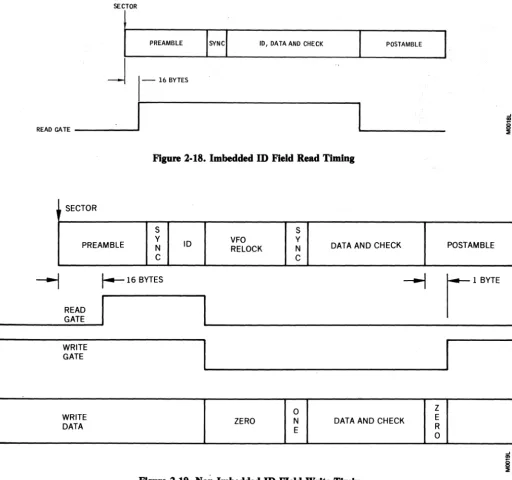
Imbedded ID Field (Figure 2-18)
The Read Gate is activated sixteen bytes after Index pulse and deactivated after the data field. Read Gate must not be activated until at least 16 microseconds after Write Gate has been deactivated or the head has been selected.
Writing
Non-Imbeded ID FIeld (Figure 2-19)
Read Gate must be activated sixteen bytes after the sec-tor pUlse. At the end of ID field, Read Gate is deacti-vated, Write Gate is actideacti-vated, and the appropriate data is written. Write Gate is deactivated one byte into the postamble.
Imbedded ID Field (Figure 2-20)
The Write Gate is activated at sector pulse time and de-activated one byte into the postamble.
SECTOR
PREAMBLE
Error HandUng
. The Martcsman internal logic monitors a number of con-ditions which,. if they occur, will compromise data in-tegrity. They are as follows:
VFO
RELOCK
Multiple Heads Selected During Write
Write Unsafe (WRTUSF) signal is set. Resets when status is read.
Write Command to Protected Head
Write Unsafe (WRTUSF) signal is set. Resets when status is read.
Power Fault
Write Unsafe (WRTUSF) signal is set. Resets when status is read.
Illegal Command Received
Bit 2 of status word is set. Resets when status is read.
Spin Acceleration/Deceleration Out of Limit
Bit 4 of status word is set. Resets when status is read. Repeated operation when this condition exists could lead to excessive wear of the head and disk and result in data loss over a period of time.
DATA AND CHECK POSTAMBLE
~ ~'"''''
READ GATE _ _ _ _ _
~I
1
1--4
BYTESU
MOO17L
Figure 2-17. Non-Imbedded ID Field Read Timing
WRITE GATE
SECTOR
PREAMBLE 10, DATA AND CHECK POsTAMBLE
j
1-
16 BYTESREAO GATE _ _ _ _ ...
1
I
Figure 2·18. Imbedded ID Field Read Timing
SECTOR
S
PREAMBLE Y N C
---1
r--
16 BYTESREAD GATE
WRITE GATE
WRITE DATA
S
ID VFO Y
RELOCK N DATA AND CHECK C
I
ZERO DATA AND CHECK
Figure 2·19. Non·Imbedded ID FIeld Write Timing
SECTOR
S
PREAMBLE Y N ID, DATA, AND CHECK C
POSTAMBLE
I!I
POSTAMBLE
~
r l B Y T E [image:27.620.50.562.45.524.2]SECTION 3
THEORY OF OPERATION
GENERAL
The Marksman Disk Drive can be divided into four major physical assemblies:
• Sealed Contamination-Controlled Unit • Drive Motor and Brake Assembly • Control Relay Assembly
• Printed Circuit Board
The Sealed Contamination-Controlled Unit contains a single disk, four read/write heads, head positioning step-per mechanism, and a recirculating air-filtration system.
The Drive Motor and Brake Assembly contains a capa-citor start/induction run, single-phase motor that rotates at 3545 rpm at 60 Hz or 2957 rpm at 50 Hz. Through a belt-pulley assembly the motor causes the disk to rotate at 2400 rpm. An electrically released spring applied fric-tion brake is mounted on the motor shaft.
DATA
...
...
WRITE DATA WRITE GATE...
DRIVERA
"""-.... WRITE ClK
COMMANDS
...
HEAD CURRENT...
STATUS CONTROL HEAD SELECT
.... lOGIC
r+
POSITIONL.
READ GATE
..
...
DATA DATA DATA
....
SEPARATOR....
...
READ ClK....
A~
' - - - PHASE lOCK ... CLOCK XDUCER
OSCillATOR ....
The Control Relay Assembly contains two 24 vdc relays under control of the drive control logic on the printed cir-cuit board. One relay transfers 110 vac to the drive motor winding and +24 vdc to the brake when energized. The other relay transfers 110 vac to the drive motor start winding when energized.
The Printed Circuit Board contains all the logic neces-sary to control all functions of the drive as well as all the read/write circuitry. The printed circuit board is divided into eight functional areas (see Figure 3-1):
• Power Regulator • Stepper Motor Drive • Drive Control Logic • Write Driver • Matrix
• Read Amplifier/Desnake • Data Separator
• Phase L9Ck Oscillator
...
"
..
...
...
R/W..
MATRIXHEAD
STEPPER STEPPER MOTOR
MOTOR
...
DRIVER
READ AMP DATA
...
[image:28.615.65.560.344.726.2]DESNAKER .... ....
Figure 3-1. Marksman Disk Drive Functional Block Diagram
The Power Regulator contains a voltage regulator and filter networks to output +24 vdc, +12 vdc, -12 vdc, and
+
5 vdc. A fused+
24 vdc input is routed directly to the stepper motor driver as well as the voltage regulator to produce the + 12 vdc output. The -12 vdc and + 5 vdc outputs are input directly from dc power supplies.The Stepper Motor Driver contains transistor switches under control of a four-bit position code and current con-trol bit from the drive concon-trol logic. Each different posi-tion code closes different switches causing current to flow through different windings of the four phase, permanent magnet stepper motor. This causes the shaft ofthe motor to rotate (step) to a specific location for each code. When stepping, the current control bit causes more current to flow through the selected windings to provide more torque. By providing a specific sequence of position codes, the drive control logic causes the motor to step clockwise or counterclockwise.
The Drive Control Logic contains a 6802 microprocessor (MPU), peripheral interface adapter (PIA), memory (ROM), programmable interval timer (PIT), and miscel-laneous control and gate logic.
The MPU executes the program stored in the memory under control of commands received through the PIA from the interface. The MPU programs one of the PIA's registers to receive commands or output status to the in-terface. The other PIA register is used to output the posi-tion code and current control bit to the stepper motor driver. The three counters of the PIT are controlled by the MPU and used for various function delays.
The Write Driver is enabled by a write (WRT/) signal from the interface and contains the logic to convert NRZ coded data from the interface to double density (MFM) coded data. It also contains error detection logic for a write unsafe condition.
The Matrix contains the logic to select a read/write head for a read or write operation.
The Read Amplifier/Desnaker contains the logic necessary to amplify, shape, and digitize the small read signals from the read/write head. The output is double density coded data.
The Data Separator contains a reference one-shot and voltage-controlled oscillator that are used to separate clock and data from the double density data. The data pulses are then converted to NRZ coded data. The data red to the interface. A read clock is also generated and sent to the interface.
The Phase Lock Oscillator has a free-running frequency of 16.89 MHz that is phase-locked to the speed of the
disk through timing pulses received from a clock trans-ducer. The phase-locked frequency is 15.36 MHz. A 19.2 KHz clock is generated from a clock divider circuit that is used for speed detection. A gated write clock is generated at the PLO frequency for write operation syn-chronization. This section also has the index transdJIcer logic that generates a pulse for each revolution of the disk.
DISK AND R/W BEAD CONFIGURATION
The ~arksman Disk Drive uses a single 14-inch dia-meter lubricated ferrous-oxide coated disk. The four read/write heads are rigidly mounted to a head-position-ing carriage as inner and outer fachead-position-ing pairs. See Figure 3-2. All heads are mounted on spring arms that are load-ed to apply a pressure of approximately 9.5 grams toward their associated disk surface. When the disk is not rotating, the heads will be, resting on the disk sur-face, however, the head pads and gimbaling are designed aerodynamically to "fly" the head on the air boundary layer created when the disk is rotating. This aerodynamic lift equalizes the spring load pressure causing the heads to fly between 19 and 22 microinches above the disk surface.
HEAD 1 HEAD 0 DISK
CARRIAGE HEAD 3 HEAD 2
'---'i
Figure 3·2. R/W Bead Configuration
DISK ZONES AND R/W BEAD POSITIONING
Each surface of the disk is divided into two recording zones and two landing zones. See Figure 3-3. Each re-cording zone consists of 213 tracks (000-212) that may be used for recording. Although all tracks are available for recording, standard practice is to hold several in reserve as spares for bad tracks. A cylinder is defined as all four recording tracks that are accessible to the read/write heads for a given track position of the head positioning mechanism. The landing zones (cylinder 229) are the designated areas, for normal power down, where the read/write heads come to rest on the disk surfacC?· Cylinder spacing on the disk surface is 0.0055 inch.
OUTER HEAD LANDING POSITION TRACK 229
OUTER HEAD TRACK 212
OUTER HEAD TRACK 000
INNER HEAD LANDING POSITION TRACK 229
INNER HEAD TRACK 212 RECORDING ZONES
[image:30.620.72.569.66.752.2]INNER HEAD TRACK 000 RECORDING ZONES
Figure 3·3. Disk Zones
DRIVE CONTROL
All functions performed by the disk drive except the actual read/write operation are under direct control of the 6802 microprocessor. Control is maintained by ex-ecution of a PROM stored program by the microprocessor. See Figure 3-4. After initialization the microprocessor is executing the wait loop portion of the . program until a command is received from the interface. Upon receipt of the command, the program jumps to the command decode subroutine. When the command is decoded, the program jumps to the subroutine that will cause the correct action to execute the command. After the command has been executed, the program jumps to the status subroutine and outputs a new status word to the interface. When the receipt of the status word has been acknowledged, the program returns to the wait loop. Following are the legal commands that will be ac-cepted and executed by the drive control logic:
• Sequence (Up/Down) • Seek
• Rezero • Head Advance • Set Sector • Diagnostic • Status
1---..1
Figure 3·4. Program Flow Diagram
I ,
POWER ON AND INITIALIZATION SEQUENCE
Initially the drive motor is stopped and the read!write heads are resting on the disk surface at cylinder 229 (landing zone). When power is turned on, a reset signal is sent to the MPU causing it to access the upper two locations of memory (see Figure 3-5). The contents of those locations is the starting address of the initialization subroutine and is loaded into the program counter of the MPU. When the program counter is loaded, the MPU starts execution. First the MPU causes the Unsafe flip-flop to be reset and then all operating constants and tables are initialized. The PIA is then programmed to output position signals to the head positioning stepper motor and to accept commands from the interface. The sector switch settings are read and the program com-putes the number sectors per track and stores the infor-mation. Head zero is then selected and Control Ready (CRDY) is sent to the interface. The program then goes to the wait loop subroutine and waits for a command to be input. The first command to be input after power-on should be a Sequence-Up command.
DATA BUS DRIVE I ADDRESS J MOTOR
L CONTROL I MEMORY 2716 HEAD SELECT ~ INTERFACE CONTROL
4 MHZ XTAL
PIA 6821
INTERRUPT
-MPU jUNDER SPEED 6802
PIT 8253 1MHZ CLOCK
1
RESET
SEQUENCE.UP OPERATION
When a command is received by the PIA, the MPU is in-terrupted. The MPU goes to the command decode sub-routine. When the command is decoded as a sequence-up, the program jumps to the sequence-up subroutine. The program causes the motor and start relays to energize and then delays two seconds after which the start relay is de-energized. Two clocks are then enabled for speed detection. After a delay of six seconds the bytes per sector and sectors per track counters are initialized. After a delay of 26.5 milliseconds the program jumps to a subroutine to check disk speed. If no index pulse is de-tected within 2.65 seconds or if two index pulses are detected within 23.5 milliseconds the spin acceleration! deceleration bit is set in the status byte and the program jumps to the sequence-down subroutine. If the disk comes up to speed with no errors the program delays three minutes and then jumps to the subroutine to posi-tion the heads over track zero. When the heads are at track zero, the status subroutine is entered. After status has been sent and acknowledged the program returns to the wait loop.
START' RUN
WRITE CURRENT CONTROL
SELECT
WRITE INHIBIT
CONTROL READY DRIVE READY STATUS
REQUEST
COM MANDS/STA TUS
ACKNOWLEDGE
INTERFACE
POSITION (Jl)
OVERSPEED INDEX
IDX SPEED WRITE CLOCK DETECT
COUNT
SECTOR
1MHZ CLOCK
[image:31.624.49.571.356.730.2]J WRITE I UNSAFE I UNSAFE F IF I
SEEK OPERATION
A seek operation requires the read/write heads be posi-tioned to the cylinder indicated in the seek command and' that the specified head be selected.
When a command is received by the PIA, the MPU is in-terrupted. The MPU goes to the command decode sub-routine. When the command is decoded as a seek, the MPU waits for the second word containing the cylinder address to be input from the interface. The received cylinder address is checked to see if it is legal (less than 213). If the address.is illegal, the status word is updated and output and the MPU returns to the wait loop. With a legal address, the read/write head indicated in the com-mand word is selected. If the new cylinder is less than 125 the head current is increased. After verifying that the disk is up to speed, the MPU computes the difference between the new and present cylinder address to deter-mine the direction of movement. The MPU then outputs position signals to the stepper motor, via the PIA, in the sequence necessary to move the head positioning carriage toward the new cylinder. After each position signal (step) the difference count is decremented and the present cylinder address is changed to indicate the new position. When the difference count reaches zero a 17 millisecond delay is started to allow the read/write heads to settle at the new cylinder. After the delay, the MPU sets the seek complete bit in the status word and then outputs it to the PIA. When the PIA receives an acknowledge for the status word from the interface, the MPU sets drive ready and goes to the wait loop.
REZERO OPERATION
A rezero operation requires the read/write heads to be positioned at cylinder zero and read/write head zero to be selected.
When the rezero command has been decoded, disk up to speed is verified and then the subroutine to position the heads at cylinder zero is entered. The cylinder zero in-dicator is checked. If on, a position signal is sent to the stepper motor to move the heads to cylinder one and then re-positioned at cylinder zero. If the cylinder zero in-dicator is off, an inward movement (to cylinder zero) flag is set. A sequence of position signals are sent to the step-per motor, via the PIA, to move the head carriage toward cylinder zero. Between each position signal the cylinder zero indicator is checked. This procedure continues until the indicator is on. Then the cylinder address is set to zero, read/write head zero is selected, and the status word is updated. The status word is output and after acknowledge control and drive ready are set. The MPU returns to the wait loop. If 235 steps are performed without detecting track zero, the MPU goes to the sequence-down subroutine.
HEAD ADVANCE OPERATION
The head advance command requires that the selected read/write head be advanced by the number indicated in the command word.
SET SECTOR OPERATION
The set sector command requires that the number of sec-tor pulses, output to the interface for each revolution of the disk, be as indicated in the second word of the command.
When the MPU decodes a set sector command it enters the set sector subroutine and waits for sector count (sec-ond command word) to be input. When the sector count is received, it is checked for a count of less than three. If less than three, the illegal sector bit is set in the status word, the status word is output and the MPU returns to the wait loop. If the sector count is legal (3-255), the MPU enters a divide subroutine where the bytes per sec-tor are computed. The PIT is then addressed and counter 2 is loaded with the bytes-per-sector count. PIT counter 3 is then loaded with the sector-per-track count. The MPU then delays 51 milliseconds to allow the counters to be synchronized with the index pUlse. Both counters are enabled by index and counter 2 is clocked every 1.04 microseconds (1 byte time). When counter 2 has decremented to zero the output pulse is sent to the interface as a sector pulse and is also used to decrement counter 3. When counter 3 has decremented to zero both counters are disabled until the next index pulse. At the end of a 51 millisecond delay the MPU outputs the status word and returns to the wait loop.
DIAGNOSTIC OPERATION
(To be supplied)
REQUEST STATUS OPERATION
The request status command requires that the requested status byte (one of eight bytes) be transferred to the inter-face. Refer to section two for the contents of the eight status bytes.
When the command decode subroutine decodes a re-quest status command, the three least significant com-mand bits are used to lead the requested status byte into a working register and then jumps to the status sub-routine. The PIA is programmed to output status and the status byte is transferred to the interface and the CACK line is activated. When the status has been receiv-ed, the system activates the CREQ line. The MPU then deactivates CACK and when CREQ goes inactive the
PIA is programmed to receive commands. The status byte is cleared except for bits 0, 1,3, and 5 and the pro-gram returns to the wait loop.
DATA RECORDING METHOD
[image:33.618.47.559.470.723.2]The method or code used by the Marksman Disk Drive for recording data is called Triple Frequency Modulation (TFM). Data is received from and transmitted to the in-terface in bit-serial NRZ (non-return-to-zero) format in real time at the writing and-reading rate ofthe disk drive. Figure 3-6 provides a comparison between NRZ, Miller Code, and TFM-coded data.
TFM data is called triple frequency because magnetic flux reversals on the recording media occur at three fre-quencies: at one bit, one and one-half bit, and two-bit cell intervals. Data bit cell time is 130.2 nanoseconds at speed, making the maximum recording frequency 7.68 megahertz (all-zeros or all-ones pattern). Minimum recording frequency would be half that, or 3.84 megahertz (for an alternate zero and one bit pattern).
TFM coding, as shown in Figure 3-6, can be reduced to the following three rules:
• A flux change occurring at the midpoint of a data cell is one data bit, regardless of polarity.
• A flux change occurring at a data cell boundary is a zero bit regardless of polarity.
• No flux reversal will occur for the first zero data bit following a one data bit.
DATA
NRZ
I I
o
1 I I 1I I I I I I
l o U D MILER CODE
~i...-"';"'_
TFM I I I I I I I
0 I 1
I I_
I
I I II D I I I I 0 C 1---2B NOTES:
1. C = CLOCK PULSE 2. D = DATA PULSE
3. B = BIT CELL IN INTERVAL
WRITE DATA RECORDING
Data to be written on the disk is sent by the interface in the form of serial.NRZ code synchronized to a bit-rate write clock provided by the control logic of the disk drive. This clock is derived from a phase-locked oscillator that is locked onto the speed of the disk. See Figure 3-7.
The head to be used must be selected prior to the actual write operation. This is done with a seek command.
A write command from the interface enables the write data system. NRZ data on the NRZIN line is clocked into a NRZ-to Miller Code converter by the same bit-rate clock supplied to the interface for strobe gating of the write data. Synchronized Miller Code data from the con-verter is passed to the write flip-flop. The write flip-flop toggles when clocked by the rising, leading edge of each pulse from the Miller Code converter. The output of this flip-flop directly controls polarity reversals of the write current drivers to effect the flux transitions in the selected head.
The write current supplied to the selected head is not the same for outer and inner heads or for all cylinder loca-tions. More current is supplied when outer heads (0 and 2) are selected than when inner heads (1 and 3) are selected. More current is supplied to the selected head to write on outer cylinders (000-125) than is supplied to write on inner cylinders. This is necessary because the tangential velocity of the disk decreases closer to the disk hub, which reduces the air pressure of the boundary
o :
0 0 1 0I
I
I
I I
I I
I I
I I
I I I
D
C~
DcLJ
I I -~~ I
I
~~~I
I I~I --~~~
__
~I
I·1·
3 B ! 2 + 1 B - j4. IB (BIT CELL TIME) = 130.2 NANOSECONDS
- 0 Q
WRITE WRITE
~
NRZ DATA FLIP/FLOP DRIVERS
MILLER CODE MILLER CODE
C Q
@
WRT CMD CONVERTER
1
-~E HEAD
I
INTERFACE
I
I
WRITE CLOCK (F)
CYLINDER 125 WRITE CURkENT HEAD SELECT
CONTROL SOURCE
LOGIC
.
t
2F
Y
HEAD
1
DISK TIMING PLD SELECT
[image:34.617.68.563.41.242.2]-I LOGIC
Figure 3·7. Write Data System Block Diagram
layer and causes the heads to fly closer to the disk surface· as"they move toward the hub. If the write current were not reduced for the inner heads and when writing on the inner cylinders, flux saturation would occur; this would reduce frequency response and increase crosstalk between tracks.
READ DATA RECOVERY
Data read from the disk is transferred to the interface in the form of serial NRZ code accompanied by a bit·rate clock provided by the disk drive for data strobing. This clock is derived from a voltage controlled oscillator that is locked onto the data stream from the read/write head. See Figure 3-8.
CROSSOVER
DETECTOR DIGITIZER
The head used for reading must be selected prior to the actual read operation in the same manner as for writing. Read is initiated when the readgate signal at the inter-face goes high. Good read data will be present on the interface NRZ output line approximately 6.77 microseconds later.
Error-free data recovery depends upon setting up ac-curate strobe windows relative to the raw data being read. This is accomplished by synchronizing a phase-locked, voltage-controlled oscillator (VeO) to the clock transitions of the read signal. This oscillator operates at the bit-rate frequency for window timing.
The series of all-zero sync 'bytes in the preamble of each record produces a TFM high frequency pattern at the bit rate. This read pattern is used for initial synchronization
DATA DETECTOR
NRZ
CONVERTER NRZ OUT READ CLOCK
INTERFACE
L-_ _ _ _ _ _ _ _ _ _ _ _ _ _ _ _ _ _ _ -e-_ _ .... b~~~~TOR VCO
READ GATE
Figure 3·8. Read Data System Block Diagram
[image:34.617.55.574.509.723.2]of the VCO by making a phase comparison between it and the VCO output. Phase differences produce a cor-rection voltage that speed up or slows down the VCO un-til it is captured and locked in phase with the all-zeros bit rate clocks.
The raw read signal from the selected head is an analog signal, the maximum amplitude of which occurs when a flux transition domain is crossed. The polarity of max-imum amplitude is indicative of the direction of the flux transitions, which, of course, alternates. This signal is amplified and phase-shifted 90 degrees so that the read signal polarity crossover points now occupy the position of maximum amplitude within the bit-cell interval. This is done because it is easier and more reliable to detect signal crossover points than to detect points of maximum signal amplitude, which can vary. See Figure 3-9.
After amplification and phase shifting, the raw read signal is processed back to digital TFM by a TFM cross-over detector and then into a stream of Miller Code data pulses. Detection windows are set up by VCO clocks that are phase-shifted 90 degrees relative to the bit time inter-val by introducing a fixed delay into the incoming stream of Miller Code pulses. Read pulses with rising leading edges within the first or last quarters of the bit time inter-val are detected as clock pulses. Read pulses with leading edges occuring within the middle half of the bit time in-terval are detected as binary 1 data pulses. Detected data is converted to bit-interval, synchronous, serial NRZ code and sent to the interface.
FIXED LENGTH SECTORING
A hardware, switch selected, fixed length sector function is automatically implemented during a power-up or an interface initiated reset sequence. Both sequences cause
the MPU to enter the initialization subroutine. During initilllization, the MPU reads the sector switches, com-putes a bytes-per-sector count which is loaded into counter 2 of the PIT. PIT counter 3 is then loaded with the sector-per-track count. Sector switch configuration is as follows: ..
NUMBER OF SECTORS SWITCHES'
SWITCH S-l NUMBER SECTOR LENGTH
OF (USING FORMAT
- 1 - 2 SECTORS IV)
CLOSED CLOSED 111 128 BYTES
CLOSED OPEN 69 256 BYTES
OPEN CLOSED 40 512 BYTES
OPEN OPEN 21 1024 BYTES
WRITE PROTECT
Data previously recorded on the disk by a particular read/write head can be protected by a hardware, switch selected, function. There is a write protect switch with each of the four read/write heads. When a switch is clos-ed and the associatclos-ed head is selectclos-ed the current source for the write drivers is inhibited. Write Protect switch configuration is as follows:
WRITE PROTECT SWITCHES
SWITCH Sl PROTECTED
HEAD
-3
-4
-5 -6 NUMBERCLOSED
-
-
-
1-
CLOSED-
- 2-
-
CLOSED-
3READ SIGNAL
~
~
i~,
~'Z:
. I1 I
TFM CROSSOVERS
~
.... 1 _ _ _ _ _ _ _ _ ---'MILLER CODE
~"-_...:.-....IIol
...
_--;;__----~
Iol
Iol
1
1 1
MILLER (DELAYED) 1, _ _ . . . .
\01 .... __
---'101 ... ---'-____ --'-_---'
1
1
I
IF CLOCK
I~
1I I
DATA WINDOWS : _
I 1 I
BIT CELLS I 1
1
1
DATA DETECT I, _ _ ~
I
I
I I
I o
1
1/481141
I
2
I
I
I
I I I I
NRZ OUT _ _ _ _ _ ---'
-3 4
I.
1
I
1
I 1
Figure 3-9. Read Data Detection
~
~~
I 1I I
1
I
I
1 1
I 1
I I
Icl
/cl
I I
I I
I 1
/cl
IIcl
I I I I
I
-5 6
[image:36.618.68.566.44.740.2]SECTION 4
OPTIONS
Several optional features are offered for the basic Marks-man Disk Drives. A description of each option follows:
'DRIVER/RECEIVER II' INTERFACE PCB
Provides receivers and line drivers for all signals at the Basic Drive Control II pcb interface which shall connect directly to flat cable for off-drive control applications. This option is the minimal drive interface requirement to be used only when no other interface/control circuitry resides within the drive enclosure, including user defined circuitry. These receivers/drivers shall be located on a 4 by 16 inch circuit board adjacent to the basic control board. Included on this board shall be standard IC socket printed circuit patterns for user breadboarding. See Figure 4-1.
DC POWER SUPPLY
An optional DC Power Supply shall be provided. High-power units will be available with varying configurations for 100-240 volts, 50/60 cycle operation. Exact combina-tions not defined at this time.
ENCLOSURE AND AC DISTRIBUTION
An optional enclosure shall provide mounting for the sealed mechanical assembly, drive control board, inter-face board and power supply. Also included is the AC distribution located on the backpanel which receives AC power through a recessed connector, fuse, and line switch and supplies primary power to the power supply and spin motor assemblies. Moreover, this enclosure shall provide all necessary cooling required by the Marksman drive with options, reduce acoustic noise level
below NC-55, increase immunity to undesired electro-magnetic radiation and personnel static discharge sus-ceptibility, and mounting for rack mount slides option.
These optional enclosures shall provide two mounting at-titudes: 1) horizontal (spindle pulley down-circuit boards up, only), 2) vertical (side nearest spin motor rotated up, only).
An additional cosmetic cover option shall be provided for desk top configurations.
RACK MOUNT SLIDES
An optional set of slides shall mount between the op-tional enclosure and standard RETMA equipment racks and shall provide forward travel of the drive to extend clear of rack for ease of maintenance and installation. This option shall be available only for horizontal drive mounting.
V.D.E. SAFETY REQUIREMENTS
An optional feature for the Marksman disk drive shall provide power and equipment safety requirements of V.D.E. Specifically, the only affected areas shall be where D.L. approved hardware is in conflict with V.D.E. specifications.
COLOR OPTIONS