ISSN Online: 2329-8413 ISSN Print: 2329-8421
Algorithm and Design Methodology to Develop a
PIFA with Optimized Reflection Coefficient for
the ISM 868 MHz Band
Bouchta Hajjine, Christophe Escriba, Daniel Medale, Jean-Yves Fourniols
LAAS-CNRS, Université de Toulouse, CNRS, INSA, Toulouse, France
Abstract
This paper presents a methodological approach to design a printed Inverted F an-tenna for the ISM 868 MHz band. For this design, the ground plane dimensions were kept fixed and the meandered radiating arm was modified to obtain the best com-promise integration/performances. This approach was then generalized to design meandered printed inverted F antennas.
Keywords
Design, Algorithm, Meandered Antenna, PIFA, ISM, Integration, Reflection Coefficient
1. Introduction
With the great progress that knows the domain of Human Health Monitoring (HHM), Internet of Things (IoT), and smart homes… more and more miniaturized systems have been developed based on the use of wireless technology for data transmission. The integration of these technologies requires the use of antennas with different frequen-cies: 868 MHz [1], 2.4 GHz (Zigbee [2], Bluetooth Low Energy [3]…), 1575.42 MHz [4] (GPS applications)…
This integration process is often confronted with antennas size and bulk problematic explaining the different research works that aim at the development of miniaturized antennas and communicating systems.
Printed antennas are currently the most used type for the different mobile devices; they have a high degree of integration and manufacturing cost included in the PCB one. Among these antennas we have chosen to study a specific one named printed inverted F How to cite this paper: Hajjine, B., Escriba,
C., Medale, D. and Fourniols, J.-Y. (2016) Algorithm and Design Methodology to Develop a PIFA with Optimized Reflection Coefficient for the ISM 868 MHz Band. Open Journal of Antennas and Propagation, 4, 166-175.
http://dx.doi.org/10.4236/ojapr.2016.44013
Received: August 8, 2016 Accepted: November 28, 2016 Published: December 1, 2016
Copyright © 2016 by authors and Scientific Research Publishing Inc. This work is licensed under the Creative Commons Attribution-NonCommercial International License (CC BY-NC 4.0).
http://creativecommons.org/licenses/by-nc/4.0/
length of the radiating arm, and the form of the stub. The different steps are described based on ADS RF software to make this paper a simplified guide to design a meandered PIFA. The second section of this paper describes the design methodology of the wave-guide and the printed antenna, the third part details the measurements results and fi-nally we present a generalized algorithm to design meandered printed inverted F an-tennas.
2. Design Methodology
2.1. Dimensioning of the Waveguide
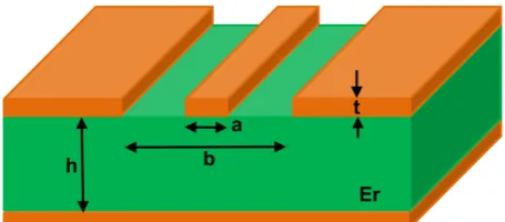
Printed antennas are generally used with coplanar waveguides to transfer the received or transmitted signals. As its name indicates, a waveguide helps to guide the electro-magnetic waves over a certain distance. It is a special form of transmission line that ex-ists in several formats and can be manufactured using the printed circuit technology. A coplanar waveguide consists of a central conductive line surrounded by the ground plane on both sides of the substrate. Figure 1 presents the geometrical characteristics of a printed waveguide.
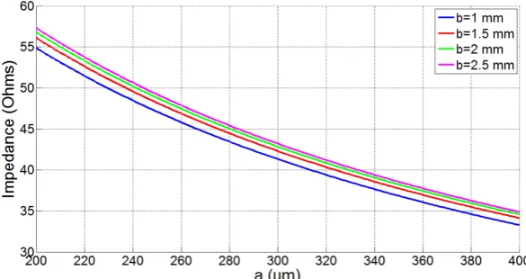
[image:2.595.260.488.586.686.2]The waveguide must present a characteristic impedance of 50 Ω to meet the antenna one. A model that permits to calculate the impedance of the waveguide is presented in [7]. Basing on this model, the variations of the waveguide impedance according to the width of the center line “a” and the distance between the two ground planes “b” are studied in Figure 2 and Figure 3 to choose the adequate dimensions. An FR4 substrate (Ɛr = 4.6) and copper tracks with a thickness of 40 µm were chosen as example. This is justified by the use of these values in the realization of the PCB presented in this paper.
Figure 2. Waveguide impedance variations according to “a” (t = 40 µm, h = 120 µm).
Figure 3. Waveguide impedance variations according to “b” (t = 40 µm, h = 120 µm).
2.2. Antenna Design
The target device is a tracking system for the monitoring of elderly suffering from cog-nitive problems. The ISM antenna is used to ensure communication with an RF beacon implemented in the residence of the monitored person or to transmit data in the case of fugues via Sigfox network [8].
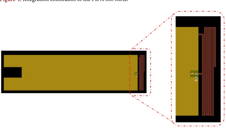
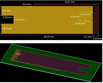
For our approach, the ground plane dimensions and form were chosen to meet the integration criteria of our research program. It will not be modified during the design and simulation process. A supplementary maximum width of 3.5 mm was fixed to in-tegrate the 868 MHz antenna as presented in Figure 4. The RF software ADS-2011 (Advanced Design System) from Keysight was chosen for this study [9].
Figure 5. Initial design of the ISM antenna.
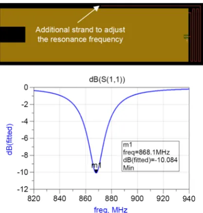
Because of the capacitive coupling between the antenna strands, the resonance fre-quency is higher compared with a quarter wave antenna that has the same total length of the unfolded strands. An initial resonance frequency is obtained using the design presented in Figure 5 at 2.12 GHz as can be noticed in Figure 6.
From these results, the length of 8.64 cm is not adequate to obtain the target fre-quency and can be taken as a starting point for the radiating arm that will then be ad-justed to tune the resonance frequency to 868 MHz.
To study the influence of the distance between the strands on the resonance fre-quency, several simulations were carried out by adjusting this distance from 50 µm to 200 µm while keeping the same total length of the radiating arm (8.64 cm). The differ-ent obtained reflection coefficidiffer-ents are presdiffer-ented in Figure 7.
[image:4.595.193.554.202.413.2]Figure 6. Reflection coefficient of the initial ISM antenna.
Figure 7. Influence of the distance between the strands
on the resonance frequency.
[image:5.595.269.478.468.687.2]Figure 9. Final design of the ISM antenna.
[image:6.595.231.515.525.685.2]3. Characterization and Measurement Results
After the modeling work based on the use of ADS software, the PIFA was carried out on a FR4 substrate (Figure 11).
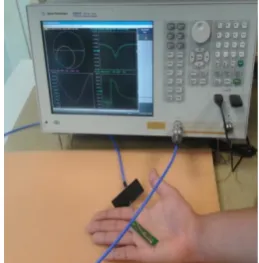
As our system is intended to be glued directly on the skin, an additional matching is necessary to take into account the presence of the human body effect. This is can be ensured using a Vector Network Analyzer (VNA) (Figure 12).
[image:7.595.248.503.227.320.2]The measured reflection coefficient of the proposed antenna is presented in Figure 13. This antenna is characterized by a good reflection coefficient S11 of −30 dB and a bandwidth of 15 MHz.
[image:7.595.308.438.355.487.2]Figure 11. Prototype of the tracking device with the integrated PIFA.
Figure 12. Reflection coefficient characterization using a VNA.
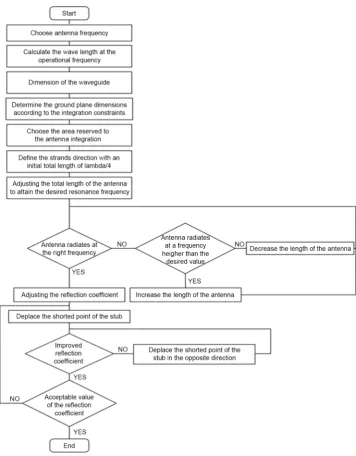
[image:7.595.266.481.520.688.2]tailed in the flowchart presented in Figure 14.
5. Conclusion
This paper presents a methodological approach to design a meandered printed inverted F antenna. This method was explained using an ISM 868 MHz printed antenna inte-grated in a tracking device for elderly suffering from cognitive problems. The design methodology was described based on the use of the RF simulation software ADS to be adapted to any form of meandered PIFA. The RF model reference was cited only for the design of the coplanar waveguide that still unchanged for any antenna type. In our stu-dies, we detailed the various constraints and parameters that must be taken into con-sideration such as the influence of the capacitive coupling between meanders on the antenna resonance frequency. This approach can be used as a guide and can be genera-lized for the simulation, design and integration of a meandered PIFA.
Acknowledgements
This work is part of SACHA project funded by French government and “Région Midi Pyrénées” in France. The partners of the project are Sigfox, Axible, Telecom Design companies, esanté and CHIVA hospital.
References
[1] Conway, G.A. and Scanlon, W.G. (2014) Compact Low-Profile Antenna for Wireless Med-ical Vital Sign Monitors at 868 MHz. The 8th European Conference on Antennas and Propagation (EuCAP 2014), The Hague, 6-11 April 2014, 830-832.
http://dx.doi.org/10.1109/EuCAP.2014.6901890
[2] Jeon, J., Jang, K., Kahng, S. and Park, C. (2014) Design of a Miniaturized UHF-Band Zigbee Antenna Applicable to the M2M/IoT Communication. 2014 IEEE Antennas and Propaga-tion Society InternaPropaga-tional Symposium (APSURSI), Memphis, TN,6-11 July 2014, 382-383.
http://dx.doi.org/10.1109/APS.2014.6904523
[3] Grković, S.B. (2014) Small Balanced Antennas for Bluetooth Applications. 17th IEEE Me-diterranean Electrotechnical Conference, Beirut,13-16 April 2014, 91-96.
http://dx.doi.org/10.1109/melcon.2014.6820513
[4] Amit, S. (2016) Design of Compact Bent Dipole Antenna and Its Array with High Gain Performance for GPS Application. 8th International Conference on Communication Sys-tems and Networks (COMSNETS), Bangalore, 5-10 January 2016, 1-6.
[5] Noordin, N.H., Yan Chiew, W., Erdogan, A.T., Flynn, B. and Arslan, T. (2012) Meandered Inverted-F Antenna for MIMO Mobile Devices. Loughborough Antennas and Propagation Conference (LAPC), Loughborough, 12-13 November 2012, 1-4.
http://dx.doi.org/10.1109/lapc.2012.6402948
[6] Loizou, L., Buckley, J., Belcastro, M., Barton, J., O’Flynn, B. and O’Mathuna, C. (2013) Mi-niaturized Inverted-F Antenna with Capacitive Loading. 7th European Conference on An-tennas and Propagation (EuCAP),Gothenburg,8-12 April 2013, 3213-3216.
[7] Simons, R.N. (2004) Coplanar Waveguide Circuits, Components, and Systems. John Wiley & Sons.
Submit or recommend next manuscript to SCIRP and we will provide best service for you:
Accepting pre-submission inquiries through Email, Facebook, LinkedIn, Twitter, etc. A wide selection of journals (inclusive of 9 subjects, more than 200 journals)
Providing 24-hour high-quality service User-friendly online submission system Fair and swift peer-review system
Efficient typesetting and proofreading procedure
Display of the result of downloads and visits, as well as the number of cited articles Maximum dissemination of your research work