International Journal of Emerging Technology and Advanced Engineering
Website: www.ijetae.com (ISSN 2250-2459,ISO 9001:2008 Certified Journal, Volume 5, Issue 11, November 2015)
90
Support Vector Machine Based Approach for Transformer’s
Differential Protection
Pankaj B. Thote
1, Manoj B. Daigavane
2, Prema M. Daigavane
31Research Scholar, 3Professor & Head of the Department, Department of Electrical Engineering, G. H. Raisoni College of
Engineering, Nagpur, India
2Principal, G. H. Raisoni Institute of Engineering and Technology for Women, Nagpur, India
Abstract—The differential relay is used for detecting the faults within the transformer. But, a conventional differential relay has many demerits. In recent times, the false counter of differential relay has been reported where it was not at all required. This brings urge among researchers for the development of advance classifier algorithm which clearly states about the faults and disturbances and helps to avoid the false tripping at times of disturbances. In this paper, Authors have used the approach based on pattern recoganization of all possible operating conditions of transformer and using support vector machine (SVM), the classification of faults and disturbances has been carried out. The proposed scheme gives good results as compared with conventional differential protection method and overall efficiency of the system found out to be 92.89%
Keywords—Discrete Wavelet Transform, Daubechies Wavelet, Differential Protection, MATLAB Simulink, Support Vector Machine.
I. INTRODUCTION
In transformer, differential protection is vastly employed to detect faults within transformer with high degree of accuracy and should be able obsolete the disturbances where tripping is not required [1], [2]. But, during switching inrush condition, recovery inrush condition, sympathetic inrush condition, over-fluxing condition etc., the over-current relay in differential circuit operates unnecessarily.
In earlier days, the harmonic restrain method is very useful for detecting the conditions like charging condition or over-fluxing condition in percentage bias differential relay scheme. But with advent in improved core of transformer and due to parallel distributed capacitances of Extra High Voltage (EHV) transmission lines, these relay reports its mal-operation [3], [4].
Since the magnetizing and fault current are non-stationary and non-periodic fast electro-magnetic transients, for processing the signals, discrete wavelet transform (DWT) is used. DWT enables the study of transients without the loss of identity.
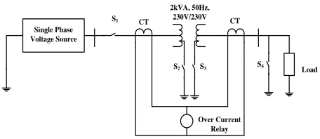
In this paper, the physical model of two winding, 2 kVA, 50 Hz, 230 V/ 230 V single phase transformer is simulated in MATLAB Simulink platform for the study of various operating conditions. Obtained results from simulations are processed through DWT to obtain the coefficients at different decomposition levels. These decomposed coefficients are used for training and testing of proposed SVM algorithm.
[image:1.612.329.557.378.477.2]II. CASE STUDY
Fig. 1 depicts the architecture of studied system,
Single Phase Voltage Source
CT CT
Load
Over Current Relay 2kVA, 50Hz,
230V/230V S1
S2 S3 S4
Fig.1: System configuration of simulated differential protection scheme
International Journal of Emerging Technology and Advanced Engineering
Website: www.ijetae.com (ISSN 2250-2459,ISO 9001:2008 Certified Journal, Volume 5, Issue 11, November 2015)
91
The parallel RLC load block is used to implement a linear load whose voltage and frequency is set equal to 230 V and 50 Hz respectively. The real and reactive power can be specified for load. Switch S1 is used to simulate the energization operation of transformer at the time of switching. Switches S2 and S3 are used to simulate the internal faults (inter-turn faults on winding 1 and 2) i.e. faults inside the CT locations. The percentage of shorted turns can be varied. Switch S4 is used to simulate external fault i.e. fault outside the CT location.
In this paper, small sized single phase transformer is used for simulation of differential relay model and can also extend its use for high capacity power transformers.
III. DISCRETE WAVELET TRANSFORM
Discrete wavelet transform is the decomposition and discretization of Continues wavelet transform. DWT provides ease of study for any kind of signals and can be reconstructed back to original state. Level of decomposition can be varied and it has different types of coefficients during each decomposition level. These coefficients obtained after decomposition process can be analysed using any of the proposed methods in literature. In this paper, Authors have used Mallat’s Multi Resolution Analysis [9] for the study of transient signals using DWT. In the process of analysis using Mallat’s scheme, the signal is first passed through FIR filter and then through the low pass filter to obtain the approximate coefficients and further it is passed through a high pass filter to get detail coefficients [10]. Generally, any transient signal has high frequency component present in it and hence called transient signal and has maximum weight-age. So, the coefficients obtained after high pass filter are called as detail coefficients. As stated earlier, the signal can be reconstructed with Inverse DWT operation using detail and approximate coefficients.
The DWT is given by,
(1)
where,
‘ ’ is the mother wavelet.
‘m’ is the scaling parameter.
‘n’ is the translation index at each decomposition level.
Selection of mother wavelet is very important for study of any signals using DWT. Mother Wavelet can be any signal which is periodic in nature i.e. average mean of signal over one cycle should be zero.
There are many readymade choices of mother wavelet available in literatures [11]. In this paper, Authors have chosen db6 as mother wavelet.
A. Daubechies Wavelet
Daubechies belongs to the family of orthonormal bases and invented by Ingrid Daubechies. It widely used choice of mother wavelet in DWT. ‘db6’ has six levels of decomposition [12].
IV. SVM BASED CLASSIFIER ALGORITHM
A. Support Vector Machine
The SVM is introduced by Boser, Vapnik & Guyon. It is method of optimization and based on feature extraction in statistical form. In general, SVM tries to learn structure of data used for its training purpose. For example, to map
X→Y, where x Є X and y Є Y (class of object). So, one can have data like (x1,y1), (x2,y2),---, (xn,yn) which can be used
for training the SVM. So, x and y will have some relationship in between them and can be given by,
y=f(x,α) (2)
where,
α is the parameter of the function
So, one can try to learn f(x,α) such that chosen function work on training data without any training error and hyperplane designed by SVM for classification will not have any false recoganization. Vapnik states that the maximum risk can be defined using empirical risk with addition term
(3)
Where,
‘h’ is the VC dimension set parameterized by α.
In general, VC dimensions means set of all functions is the maximum number of points separated by all the possible means.
International Journal of Emerging Technology and Advanced Engineering
Website: www.ijetae.com (ISSN 2250-2459,ISO 9001:2008 Certified Journal, Volume 5, Issue 11, November 2015)
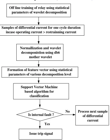
92 Off line training of relay using statistical
parameters of wavelet decomposition
Samples of differential current for one cycle duration incase operating current > restrainning current
Normallization and wavelet decomponistion using db6
mother wavelet
Formation of feature vector using statistical parameters of various decomposition level
Support Vector Machine based algorithm for
classification
Is internal fault ?
Issue trip signal Yes
Process next sample of differential
[image:3.612.60.282.127.408.2]current No
Fig. 2: Schematic block diagram of the proposed scheme
V. DATA ACQUISITION
For internal faults, different sets of data are generated both for training and testing purpose. For example in internal faults, different cases are observed like inter-turn fault on primary and secondary sides, inter-turn faults during switching operation and inter-turn faults with windings shorted. In case of inter-turn fault on primary side, different percentages of shorting ratio are considered like 16%, 33%, 50%, 66%, 83% and 100%. Similarly, data is collected on secondary side of transformer. Also during inter-turn fault during switching from 0 sec. to 0.02 sec. at step size of 0.002sec. on primary side as well as secondary side of the transformer. Also for inter-turn faults at different loading conditions both at primary and secondary sides. Cumulatively, from all the cases stated above 454 cases are generated.
Similarly for non-fault conditions like saturation and over-fluxing conditions, data has been collected of order 222. Overall data generated for training and testing purpose of machine is 676.
VI. SIMULATION RESULTS
Out of all the possible operating conditions transformer can encounter, following is the list of all the possible events.
A. Loaded condition B. Internal faults C. External faults
D. Magnetizing inrush condition E. Over-fluxing condition
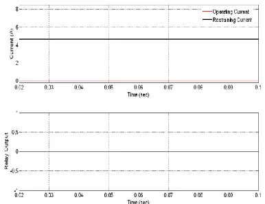
A. Loaded Condition
During loaded condition, the load current should be less the restrain current and relay should not operate. In Fig. 3, relay output is at zero magnitude level which represents the correct operation of relay.
Fig. 3: Relay output for load condition with operating and restrain current.
B. Internal Fault
[image:3.612.341.543.382.518.2]International Journal of Emerging Technology and Advanced Engineering
Website: www.ijetae.com (ISSN 2250-2459,ISO 9001:2008 Certified Journal, Volume 5, Issue 11, November 2015)
[image:4.612.68.271.145.287.2]93 Fig. 4: Relay output for an internal fault with operating and restrain
current.
C. External Fault
[image:4.612.341.542.206.336.2]When line to ground fault occurs at load end outside CT location, the relay should not operate. Fig. 5 shows the operating current less than the restraining current and the relay output is low, which ensures the correct operation of relay and provides the through fault stability to system.
Fig. 5: Relay output for an external fault with operating and restrain current.
D. Magnetizing Inrush Condition
The magnetizing inrush condition occurs in transformer during its energization because of core saturation. There is also possibility of magnetizing inrush condition when core of transformer is partially saturated. This current can be higher magnitude of order 8 to 10 times that of full load current. In this case, due to flux building in core, heavy current will be drawn and operating current will be greater than restrain current.
But, this is not fault. So, relay should not operate. SVM based algorithm differentiate this condition from that of internal fault condition and does not issue any relay command. Fig. 6 shows the correct operation of relay during energization.
Fig. 6: Relay output for inrush current with operating and restrain current.
E. Over-Fluxing Condition
[image:4.612.71.264.410.559.2]Under normal operating condition, transformer develops a maximum flux density in the core which is directly proportional to magnitude of applied voltage and is inversely proportional to frequency. Any deviation of these quantities from its nominal magnitudes, transformer core is subjected to over-fluxing condition but should not operate. Fig. 7 the correct operation of relay even when operating current is majority of times greater than restrain current (when supply voltage is increased by 25% and frequency is reduced by 5%).
Fig 7: Relay output for over-fluxing Condition with operating and restrain current.
VII. CONCLUSION
[image:4.612.343.555.516.623.2]International Journal of Emerging Technology and Advanced Engineering
Website: www.ijetae.com (ISSN 2250-2459,ISO 9001:2008 Certified Journal, Volume 5, Issue 11, November 2015)
94
The mal-functioning of conventional harmonic restrain method has been rectified using combination discrete wavelet transform and SVM. The all possible operating conditions are passed through powerful wavelet transformation to obtain the data in form of coefficients. These statistical data then used for training and testing purpose of SVM. In this paper, Authors have used 30% data for training purpose and 70% data for testing purpose and found the efficiency of proposed algorithm to be 92.89%. This efficiency can be further improved by using majority of collected data for training purpose and remaining data for testing purpose but, that will slow down the operation of the system resulting in delayed decision making.
APPENDIX
1) Winding resistances R1= 0.027603946 p.u. R2= 0.027603946 p.u.
2) Winding inductances L1= 0.022495099/314.5 p.u. L2=0.022495099/314.5 p.u.
3) Magnetizing
resistance Rm= 500 p.u.
4) Magnetizing
inductance Lm=80 p.u.
REFERENCES
[1] J.Lewis Blackburn, Thomas J.Domin, Prorective Relaying Principles and Applications, CRC Press.
[2] www.severon.com.au
[3] Pelin L.Mao and Raj K.Aggarwal, A Novel Approach to the Classification of the Transient Phenomena in Power Transformers Using Combined Wavelet Transform and Neural Network, IEEE Transactions on Power Delivery, vol. 16,no.4,pp. 654-660,October 2001.
[4] Monsef, H., Lotfifard, S, Internal fault current identification based on wavelet transform in power transformers Electric Power Systems Research, 2007.
[5] R.Bouderbala, H.Bentarzi and A.Quadi, Digital differential relay reliability enhancement of power transformer, International Journal of Circuits, Systems and Signal Processing,vo.5,issue 3,pp 263-270,2011.
[6] Kadri Kadriu, Gazmend Kabashi, Misoperation of the differential protection during the dynamic process of faults in the secondary protection circuit. Differential protection modeling with Matlab software and fault simulation, Proceedings of the 5th WSEAS International Conference on Power Systems and Electromagnetic Compability, Corgu, Greece, pp 156-162, August 23-25,2005. [7] Haihui Song, Fangming Zhao, Di He, Simulation study on Internal
fault of Transformer, 2012 International Conference on Solid State Devices and Material Science, Physics Proceeding. 25, pp 459-464. [8] F. Fard Ali Asghar, K. P. Basu, Reduction of three-phase
transformer magnetizing inrush current by use of point on wave switching, Proceedings of 2009 IEEE student Conference on
Research and Development,16-18 November 2009,UPM
Serdang,Malyasia.
[9] S. Mallat: A wavelet Tour of Signal Processing, Academic Press, San Diego 1998.
[10] Shariatinasab, Reza, Mohsen Akbari, and Bijan Rahmani. Application of Wavelet Analysis in Power Systems, Advances in Wavelet Theory and Their Applications in Engineering Physics and Technology, 2012.
[11] Ms. Sonam Malik and Mr. Vikram Verma, Comparative analysis of DCT, Haar and Daubechies Wavelet for Image Compression, International Journal of Applied Engineering Research, ISSN 0973-4562 Vol.7 No.11 (2012)