International Journal of Emerging Technology and Advanced Engineering
Website: www.ijetae.com (ISSN 2250-2459,ISO 9001:2008 Certified Journal, Volume 5, Issue 6, June 2015)
109
Implementation of Image Fusion Techniques for Remote
Sensing Application
Gore Tai M
1, Prof. S I Nipanikar
2 1PG Student, Department of E&TC, PVPIT, Pune, India 2Assistant Professor, Department of E&TC, PVPIT, Pune, India
Abstract—in remote sensing; there are many applications that simultaneously require the high spatial and high spectral resolution from multisensory images. Image fusion is required to combining relevant information from two or more images into a single image which is more informative than any of the input images. In this paper, we propose an image fusion approach based on Discrete Cosine Transform (DCT), Discrete Wavelet Transform (DWT) & Stationary Wavelet Transform (SWT) and the hardware implementation of fused image using Discrete Wavelet Transform on FPGA platform and their comparative analysis with the help of parameter evaluation for various test images.
Keywords— Discrete Cosine Transform (DCT), Discrete Wavelet Transform (DWT), Fusion, Multi-Sensor, Stationary Wavelet transforms (SWT).
I. INTRODUCTION
Recently, the image fusion has great importance in digital image processing. Image fusion is a data fusion technology which keeps images as main research contents. The main goal of image fusion is to integrate complementary multisensory, temporal and multi-view information into one new image which is more informative than any of the input images. The multisensory data in the field of remote sensing, medical imaging may have multiple images of the same scene providing different information. It is not possible to have a single image that contains all the information of objects in the image. To achieve this, image fusion is required. Image fusion is the process of combining relevant information from two or more images into a single image which is more informative than any of the input images. Data fusion has been widely used in remotely sensed image analysis at pixel, feature, and decision level. Images used for fusion can be taken form multimodal imaging sensors or from the same imaging sensor at different times [1].
The IR images contain information that is not the same as in the visible range images. The IR reflectance of objects may be different than for the visible light.
Foliage is often much more intensive in IR images and some semitransparent objects may become transparent in IR wavelengths and vice versa. One possible solution comes from the field of data fusion of these images with different contents could be utilized to enhance image quality of object if suitable cameras are available. A number of methods have been proposed for merging infrared images with visible spectrum images concentrate heavily on the surveillance and remote sensing applications [10]. Fusion methods can be broadly classified into two that is spatial and transform domain fusion. But spatial domain methods such as Averaging, Brovery, and Principle Component Analysis (PCA) based methods produce spectral distortion in the fused image. This is particularly crucial in remote sensing if images to merge were not taken at the same time. In the last few years, multi-resolution analysis has become one of the most promising methods for the analysis of images in remote sensing. Recently proposed new approach to image merging that uses a multi-resolution analysis procedure based upon wavelet transform. The DWT and SWT based method will be more efficient for fusion. Stationary Wavelet Transform (SWT) is similar to Discrete Wavelet Transform (DWT) but the only process of down-sampling is suppressed that means the SWT is translation-invariant [2]. But the image fusion algorithm based on DWT is faster developed image fusion method in recent decade. Discrete Wavelet Transform has good time frequency characteristics. DWT is defined as considering the wavelet transform of the two registered input images (Infrared and Visible) together with the fusion rule. Then, the inverse wavelet transform is computed, and the fused image is reconstructed.
II. IMAGE FUSION
International Journal of Emerging Technology and Advanced Engineering
Website: www.ijetae.com (ISSN 2250-2459,ISO 9001:2008 Certified Journal, Volume 5, Issue 6, June 2015)
110 Fig.1 General Image fusion processes
The fused image is obtained by taking an inverse multi-scale transform (IMST). Multi-multi-scale transforms are useful for analyzing the information content of images for the purpose of fusion.
III. FUSION ALGORITHMS
A. Discrete Cosine Transform
Discrete cosine transform is extensively used in digital image processing. Large DCT coefficients are concentrated in the low frequency region. DCT based image fusion technique can be used for application which does not require high quality and precision [2].
Fig.2 Process flow graph of DCT [2]
Step1: To perform DCT, an image is first subdivided into blocks of 8x8 pixels as shown in fig.2
Step2: The DCT is performed on each block and fusion rules are applied to get fused DCT coefficients.
Step3: Then apply the inverse DCT on the fused coefficients to produce the fused image.
B. Stationary Wavelet Transform
The discrete wavelet transform is not a time in-variant transform. The way to restore the translation invariance is to average some slightly different DWT, called un-decimated DWT. The stationary wavelet transform is similar to discrete wavelet transform (DWT) but the only process of down-sampling is suppressed that means the SWT is translation-invariant [11].
Fig.3 1st level decomposition using SWT [13]
Step1: The source images decomposed using SWT at one level resulting in three details sub bands and one approximation sub band (A, H, V and D bands).
Step2: After getting coefficient, take the average of approximate parts of an images shows fig.3
Step3: We have to take the absolute values of horizontal details of the image and then subtract the second part of image from first.
D = (abs (H1L2)-abs (H2L2))>=0
Step4: After that fused horizontal part make element wise multiplication of D and horizontal detail of first image and then subtract another horizontal detail of second image multiplied by logical not of D from first.
Step5: To obtain the fused vertical & details of image after finding D for vertical and diagonal parts.
Step6: Repeat same process for fusion at first level.
Step7: Take inverse SWT to get fused image.
C. Discrete Wavelet Transform (DWT)
Wavelet transform is a multi-decomposition of an image in a bi-orthogonal basis and results in a non-redundant image representation. This basis is called as wavelets i.e. they are the functions generated from one single function called as mother wavelet. This transform is more suitable then Fourier transform and Discrete Cosine Transform since wavelet transform has the ability to represent the signal both in time and frequency domain [8].
1. DWT decomposition of images.
International Journal of Emerging Technology and Advanced Engineering
Website: www.ijetae.com (ISSN 2250-2459,ISO 9001:2008 Certified Journal, Volume 5, Issue 6, June 2015)
111
Fig.4 1st DWT decomposition scheme
DWT coefficients for Haar wavelet transform-
2 1 2 1 L 2 1 2 1 H
Approximation and Detail coefficients are as follows-
' xL xL d c b a A 2 d c b a A Detail coefficients:-
2 d c b a H
2 d b c a V
2 d c d a D2. Process flow of DWT image fusion
Fig.5 The scheme of image fusion using DWT
Step 1: Wavelet transform is first transformed on each source images to generate a wavelet coefficients based on haar wavelet transform.
Step 2: By using different fusion rules which are average, minimum and maximum rules fuse each decomposition levels.
Step 3: Apply inverse DWT on fused decomposition levels, to reconstruct the original image that is fused image.
IV. RESULTS
A. Simulation Results
In the proposed algorithm, image fusion of Infrared and Visible images by using different image fusion techniques such as DCT, SWT & DWT. Fused images were generated are shown below:-
(a) (b)
(c) (d)
International Journal of Emerging Technology and Advanced Engineering
Website: www.ijetae.com (ISSN 2250-2459,ISO 9001:2008 Certified Journal, Volume 5, Issue 6, June 2015)
[image:4.612.112.228.134.242.2]112 (g)
Fig.6 Experimental images (a) visible image (b) IR image (c) fused image by DCT (d) fused image with DWT minimum rule (e) fused image with DWT weighted average rule (f) fused image by SWT (g)
fused image by DWT maximum rule.
B. Evaluation of image quality with proposed metric
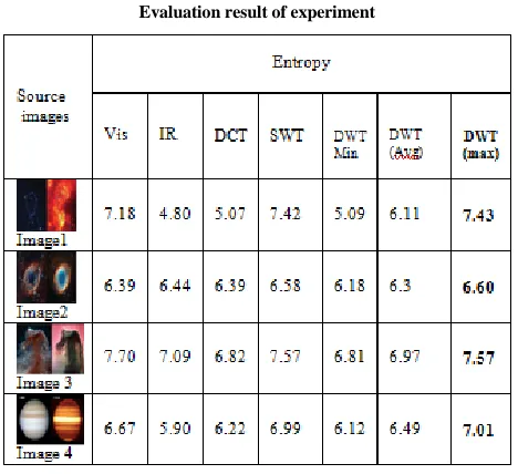
Following Table. I demonstrate the quality measures for different image fusion techniques with respect to entropy.
Entropy- Entropy is quantifies the quantity of information contained in the fused image. Entropy of the fused image is calculated using equation (1)
H= -
10
L
i hf(i) log2 hf (i) (1)
Here hf is the normalized histogram of fused image and L is the no. of gray levels.
Table I.
Evaluation result of experiment
According to above output images and the values of entropy, we can find that the DWT maximum fused image and their value have large entropy, which means they have more information than the source image.
V. CONCLUSIONS
In this paper, we observe simulation results by using different image fusion techniques. A fusion technique such as DCT is used for real time application but does not produce high quality & precision. SWT produce maximum information but hardware point of view, it require more storage capability. Whereas DWT based fusion techniques provides us good fused images. Experimental results prove that: We are selecting DWT maximum fusion rule for hardware implementation, because it provides more information for good contrast [2].
VI. FUTURE WORK
The image fusion techniques will be ported on FPGA hardware and we will prove our design in real time.
REFERENCES
[1] C. Pohl and J. L. van Genderen, “Multisensor image fusion in remote sensing: Concepts, methods and applications,” Int. J. Remote Sens., vol. 19,no. 5, pp. 823–854, 1998.
[2] Desale, Rajenda Pandit, and Sarita V. Verma. “Study and analysis of PCA, DCT & DWT based image fusion techniques." In Signal Processing Image Processing & Pattern Recognition (ICSIPR), 2013 International Conference on, pp. 66-69. IEEE 2013.
[3] P. Phanindra, J. Chinnababu, V.Usha Shree, “FPGA Implementation of Medical Image Fusion based on DWT”, ISSN:2272-128x, vol.3, issues 9, sep-2013, pp-118-122.
[4] V.Tsagaris, "Objective evaluation of color image fusion methods,"Optical Engineering, vol. 48, p. 066201, 2009.
[5] Michal Bartys, Barbara Putz, Adrian Antoniewicz, “Real-time Single FPGA-based multimodal image fusion system”, IEEE international conference on imaging systems and techniques, fusion 2012, in print. [6] M. Wielgus, A. Antoniewicz, M. Bartys, B. Putz, “Fast and Adaptive Bidimensional Empirical Mode Decomposition”, IEEE 15th
Conference on Information Fusion, Fusion 2012, in print.
[7] Yihui Yuan, Hui Xu, Zhuang Miao, Feng Liu, Junju Zhang, Benkang Chang, “Real-time Infrared and Visible Image Fusion Sytem and Fusion Image Evaluation”, IEEE Symposium on Photonics and Optoelectronics, fusion 2012, in print..
[8] Laure.J.Chipman, Timothy M.Orr, Lewisn.Graham, “Wavelet and Image Fusion”, 1995 IEEE, Jan 2010, pp-248-249.
[9] Amrit Mann, Rajbhupinder Kaur, “Colored Image Fusion using Different Methods”, Iternational Journal of Information Technology and Engineering (IJITME), ISSN: 2349-2865, Vol.1, Issues-5, Aug 2014, pp. 1-9.
[10] J.Jenirha Christinal, T.Jemima Jehaseai, “A Novel Color Image Fusion for Multi-sensor Night Vision Images”, International Journal of Computer Application Technology and Reaserch, ISSN: 2319-8656, vol.2, Issues 2, 2013, pp. 155-159.
[image:4.612.52.286.438.652.2]International Journal of Emerging Technology and Advanced Engineering
Website: www.ijetae.com (ISSN 2250-2459,ISO 9001:2008 Certified Journal, Volume 5, Issue 6, June 2015)
113 [12] K. Anil Kumar, M. Vijay Kumar, “ Implementation of Image
Processing Lab using Xilinx System Generator”, Advances in Inage and Video Processing, ISSN: 2054-7412, Vol.2, Issue 5, Sept 2014.