N o v el s of t b e n d i n g a c t u a t o r
b a s e d p o w e r a u g m e n t a ti o n h a n d
e x o s k el e t o n c o n t r oll e d b y h u m a n
i n t e n ti o n
Al-F a h a a m , H , D a vi s, ST, N e f ti-M e zi a ni, S a n d T h e o d o ri di s, T
h t t p :// dx. d oi.o r g / 1 0 . 1 0 0 7 / s 1 1 3 7 0-0 1 8-0 2 5 0-4
T i t l e
N o v el s of t b e n d i n g a c t u a t o r b a s e d p o w e r a u g m e n t a ti o n
h a n d e x o s k el e t o n c o n t r oll e d b y h u m a n i n t e n tio n
A u t h o r s
Al-F a h a a m , H , D avi s, ST, N e f ti-M e zi a ni, S a n d T h e o d o ri di s,
T
Typ e
Ar ticl e
U RL
T hi s v e r si o n is a v ail a bl e a t :
h t t p :// u sir. s alfo r d . a c . u k /i d/ e p ri n t/ 4 6 8 1 4 /
P u b l i s h e d D a t e
2 0 1 8
U S IR is a d i gi t al c oll e c ti o n of t h e r e s e a r c h o u t p u t of t h e U n iv e r si ty of S alfo r d .
W h e r e c o p y ri g h t p e r m i t s , f ull t e x t m a t e r i al h el d i n t h e r e p o si t o r y is m a d e
f r e ely a v ail a bl e o nli n e a n d c a n b e r e a d , d o w nl o a d e d a n d c o pi e d fo r n o
n-c o m m e r n-ci al p r iv a t e s t u d y o r r e s e a r n-c h p u r p o s e s . Pl e a s e n-c h e n-c k t h e m a n u s n-c ri p t
fo r a n y f u r t h e r c o p y ri g h t r e s t r i c ti o n s .
https://doi.org/10.1007/s11370-018-0250-4
O R I G I N A L R E S E A R C H P A P E R
Novel soft bending actuator-based power augmentation hand
exoskeleton controlled by human intention
Hassanin Al-Fahaam1 ·Steve Davis1·Samia Nefti-Meziani1·Theo Theodoridis1 Received: 31 August 2017 / Accepted: 15 April 2018
© The Author(s) 2018
Abstract
This article presents the development of a soft material power augmentation wearable robot using novel bending soft artificial muscles. This soft exoskeleton was developed as a human hand power augmentation system for healthy or partially hand disabled individuals. The proposed prototype serves healthy manual workers by decreasing the muscular effort needed for grasping objects. Furthermore, it is a power augmentation wearable robot for partially hand disabled or post-stroke patients, supporting and augmenting the fingers’ grasping force with minimum muscular effort in most everyday activities. This wearable robot can fit any adult hand size without the need for any mechanical system changes or calibration. Novel bending soft actuators are developed to actuate this power augmentation device. The performance of these actuators has been experimentally assessed. A geometrical kinematic analysis and mathematical output force model have been developed for the novel actuators. The performance of this mathematical model has been proven experimentally with promising results. The control system of this exoskeleton is created by hybridization between cascaded position and force closed-loop intelligent controllers. The cascaded position controller is designed for the bending actuators to follow the fingers in their bending movements. The force controller is developed to control the grasping force augmentation. The operation of the control system with the exoskeleton has been experimentally validated. EMG signals were monitored during the experiments to determine that the proposed exoskeleton system decreased the muscular efforts of the wearer.
Keywords Soft robotics·Soft mechanism·Wearable robot·Artificial pneumatic rubber muscle·Modelling
1 Introduction
In the increasingly rapid development of recent decades, one important area of innovation has been alleviating heavy tasks [1]. Human–robot power assistance refers to the utilization of robotics systems to raise human functionalities in various operational cases [2]. Generally, the power assistance of peo-ple’s functionalities using robotic systems refers exclusively to augmentation in mechanical abilities including movement control and limbs output force. This involves complex func-tionalities and taking advantage of perceptual abilities. There are cases of working conditions in which human–robot assis-tance can form a fundamental part of the operation, e.g. tasks for wreckage elimination after an earthquake in which human
B
Hassanin Al-Fahaam1 Autonomous Systems and Robotics Research Centre, School
of Computing/Science and Engineering, The University of Salford, Manchester M5 4WT, UK
employees, wearing such devices, can move and work in a more adaptable and precise way than machines like excava-tors or cranes.
Different situations are exemplified by functions in which the number of repetitive actions, rather than the scale of loads to be lifted, is high and turns into the critical factor for diminishing fatigue, and thus maintaining long-term lev-els of optimal functioning. A wearable robot is a particular kind of wearable gadget that is utilized to improve a human’s movement as well as physical capabilities. Wearable robots are otherwise called bionic-robots or exoskeletons. One of the general features of an exoskeleton is that it includes physical equipment for supporting the human movement. Exoskele-tons can help people to walk, which might be utilized for post-surgery or rehabilitation issues.
decade have concentrated on the significance of designing exoskeleton robots able to produce forces at the level of the upper-limbs or different parts of the wearer body. As a result, an expanded definition of the robotic community to include exoskeleton robots has been registered. The major part of recent research on wearable robots derives from their appli-cation in neuro-rehabilitation, where the exoskeleton system is utilized to dynamically help the patient’s appendage with the execution of particular activities [3,4].
This paper depicts the development of novel bending pneumatic soft actuators for utilization in a power augmen-tation soft glove. A mathematical model of the new bending actuator has been developed and verified against experi-mental results. This soft actuator is then deployed in an exoskeleton glove for hand power augmentation for healthy or partially disabled individuals. This soft exoskeleton is able to fit any adult hand size without the need for any mechanical system changes or calibration. A hybrid cascaded position/force intelligent control system has been developed to control the proposed prototype. The performance of the proposed system has been proven experimentally. The poten-tial beneficiaries of the system are post-stroke patients and the elderly who have reduced strength and the exoskeleton may allow for increased independent daily living. There are potentially significant philological benefits to be gained from enhanced patient independence.
2 Human hand soft exoskeletons
The human hand consists of four fingers and a thumb [5] and each finger has three joints (see Fig.1); the thumb has a different bone structure and its joints are named differently. The index, middle, ring, and little finger joints are named as follows:
Metacarpal-phalangeal joint (MCP)root joint of the fin-ger; connects the metacarpal bone to the proximal phalange. Proximal interphalangeal joint (PIP)middle joint of the finger; connects the proximal phalange to the intermediate phalange.
Distal interphalangeal joint (DIP)terminal joint of the finger; connects the intermediate phalange to the distal pha-lange.
The thumb finger joints are named:
Carpal-metacarpal joint (CMC)root joint of the thumb; connects the metacarpal to the carpal bones at the base of the wrist.
Metacarpal-phalangeal joint (MCP)middle joint of the thumb; connects the metacarpal to the proximal phalange.
Interphalangeal joint (IP)terminal joint of the thumb; connects the proximal phalange to the distal phalange.
For the fingers (index through little), the carpals and metacarpals can be assumed to be fixed at the wrist joint. In
Fig. 1 Human upper-limb anatomy [5]
reality, there is a small degree of abduction in the metacarpals (which can be distinguished by pressing the little and index fingers together); however, this is a generally a minor part of the general hand movement. The three bones in the finger are the proximal phalange, the middle phalange, and the distal phalange. For the thumb, the metacarpal moves significantly and there are just two phalangeal bones: the proximal pha-lange and the distal phapha-lange (proximal, middle, and distal phalanges).
[image:3.595.310.538.57.288.2]detecting the human intentions and supports any movements of the wrist joint. This device is also small and lightweight, so that patients can use it in a clinic or at home. Actuator units receive a biological signal from the muscles to decide which movement the patient needs. Xiang et al. [9] presented a one DOF wrist and forearm rehabilitation device for stroke patients. This device is capable of providing different training modes and creating a virtual-reality game for the patient to perform the training. The device had been examined by two stroke patients and one chronic patient with left hemiplegia, and the results were successful. The robot is reconfigurable to each rehabilitation mode, and it is portable. Chen et al. [10] presented a rehabilitation robot called NTUH-ARM to rehab the human upper-limb. This robot has 7 DOFs actuated by FAULHABER DC motors to perform most upper-limb reha-bilitation exercises. Two 6-axis force/torque sensors were used to provide a movement capture for the monitoring and the controller. This device was tested clinically by six patients to evaluate the performance of the robot, and the results were examined by physical therapists, also revealing promising results. Otten et al. [11] developed a hydraulically powered self-aligning upper-limb exoskeleton for identify-ing the reflex properties of the shoulder and elbow joints in stroke patients. Powerful hydraulic motors are used to actuate this rehabilitation device and also to generate high torques and power using lightweight actuators. This exoskeleton is also used for diagnostic purposes to diagnose the level of muscle/neuron damage in the upper-limb. Vitiello et al. [12] proposed a powered elbow exoskeleton designed for post-stroke physical rehabilitation, ensuring maximum safety and comfort to the patient. They used lightweight mechanical materials to minimize the pressure on the skin. This device has 4 DOFs to drive elbow flexion and extension move-ments. These DOFs are actuated hydraulically by using two cylinders and tendons to enable suitable control for the joint movements under rehabilitation training conditions.
Force assistive or rehabilitation exoskeletons have to be: (i) inherently safe because they are in direct contact with humans, (ii) lightweight, for easy use and portability, and (iii) able to fit a person without extensive adjustment and cali-bration. Unfortunately, conventional actuators and inflexible, serial connection manipulators are not fully appropriate for these prerequisites. In any case, the generally new field of soft robotics technology may be able to address these issues. Polygerinos et al. [13] developed an exoskeleton glove using soft muscles made from elastic materials such as liq-uid silicon. The actuator design is complex meaning the manufacturing process is slow and laborious. The Actuation force is comparatively low at 8N although the authors say this is sufficient for many tasks of daily living. The overall glove weighs 285 g which although lighter than other hand exoskeletons is still a significant load to support at the hand for extended periods, especially for the elderly or weak. The
same authors used EMG signals to control their exoskeleton [14]. However, the research faced problems with the releas-ing movements because the EMG signal characteristics of the release movements are similar to the wrist joint movements and this resulted in a conflict between the signals.
Toya et al. [15] also developed force assistance glove based on moulded bending muscles. The actuators used in this prototype meant the glove was more lightweight than Polygerinos’ at 180 g but the output force was just 3 N per finger, and the operating pressure was limited to 300 kPa. A 3D-printed soft actuator is also presented by Polygerinos et al. [16] to create a rehabilitation glove. This prototype is lighter still (160 g) but still suffers from comparatively low force output. There is therefore a need to develop gloves with higher force output and reduced weight which can be manu-factured simply and rapidly.
Pneumatic soft artificial muscles are driven by air pres-sure and are created from soft materials such as rubber tubes acting as a bladder and braided sleeves. They are inherently safe actuators for direct human interaction because of their lightweight and lack of rigid parts. These features also make them suited to use in exoskeleton robots. The pneumatic arti-ficial muscle (PAM) [17], also called McKibben Muscle, is a tube-like an actuator that is characterized by an increase or decrease in length when inflated or deflated [18]. The PAM is generally designed and constructed from a rubber or latex bladder tube which is encased in a braided sleeve and secured to rigid caps at both terminal ends. The PAMs transform applied pneumatic pressure into either a compres-sive or tensile force. These actuators have many advantages, for example, high power to weight ratios, the ability to be used as a direct drive, inherent safety, compliance and low cost.
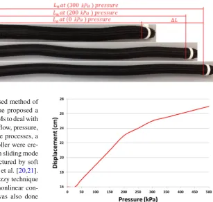
Fig. 2 The extensor muscle with different supplied pressures, where:Lois the muscle length at the rest,Lnis the muscle length under pressurization andLis the amount of length increase
Shen [17] presented a nonlinear model-based method of control of PAM servo devices. This technique proposed a controller method for servo systems-based PAMs to deal with the four major processes in these devices: the flow, pressure, force, and load dynamics. Depending on these processes, a fully nonlinear model and the efficient controller were cre-ated. A position control approach depending on sliding mode controller relay type for a robot arm manufactured by soft pneumatic actuators was developed by Sárosi et al. [20,21]. An adaptive controller based on fast hybrid fuzzy technique was proposed by Hosovsky et al. [22] as a nonlinear con-troller for PAM, and the adaptive control was also done by using Genetic Algorithms. Nuchkrua and Leephakpreeda [23] presented a real-time conventional PID self-tuning by using fuzzy logic to create an efficient nonlinear controller for PAMs. A tracking controller for PAM was presented by Qian et al. [24], who used a combination between a conven-tional sliding mode control method and a fuzzy control to create a robust adaptive controller. Finally, a fuzzy-PID self-tuning controller was also used by Sun et al. [25] to control a damping seat based on PAMs, used in a crawler construc-tion vehicle. Many controller methods have been developed in this area (soft pneumatic actuators) in many industrial and medical applications because this is an interesting field for researchers to create safer robots and machines for human direct interaction.
3 Bending artificial muscle
The novel bending artificial muscle has been developed using a braided sleeve with a minimum diameter of 10 mm and a maximum of 23 mm, a tubular rubber bladder with length of 16 cm and diameter of 10 mm and 3D-printed endcaps (one has a hole for air supplied pressure). However, the sleeve length was double that of the bladder, giving the muscles a resting diameter of 23 mm. Due to the braid being longer than the bladder, the muscle will extend in length when the supplied pressure is increased; this type of muscle is known as an extensor. First, the rubber tube is secured at each end to the two endcaps, the sleeve in then places around this and then again secured to the two endcaps using a cable tie. Due
Fig. 3 The length of the proposed extensor muscle related to the sup-plied pressure
to the fact the braid is longer than the bladder, it must be compressed in length. Figure2illustrates the behaviour of the proposed extensor artificial muscle under different sup-plied pressures (without any load attached). It can be seen that the extensor artificial muscle expands as the supplied air pressure is increased. The maximum increase in the mus-cle length was measured experimentally to be 68% under 500 kPa supplied pressure. Figure3shows the characteristic behaviour of the proposed extensor actuator in relation to the supplied pressure. During this operation, an axial extensile force is produced at the free end of the muscle.
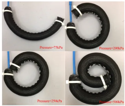
The bending artificial muscle is derived from the extend-ing muscle by reinforcextend-ing one side of it usextend-ing a fixed length thread (inextensible) with a 500N breaking strength and leav-ing the other side free. Figure 4 shows the same bending muscle with different applied pressures.
[image:5.595.234.542.53.345.2]rela-Fig. 4 The bending artificial muscle with different pressures
tionship between the provided pressure and the curve angle of the proposed bending actuator. It can be seen that the bend angle is proportional to the air pressure. The bending angle was measured by photographing the actuator at each pres-sure and then manually measuring the angle between a line extended from the free end of the actuator and the vertical axis.
Whilst there have been pneumatic bending actuators pro-duced in the past, as discussed in Sect.2, this work presents a novel McKibben muscle-based bending actuator. As stated, the intended application for the actuators is in a force aug-mentation glove. Therefore, the design specifications of the glove will determine the required actuator specifications. The glove is intended to be lighter in weight than the sys-tems described in Sect. 2, with a target weight of 150 or 50 g per digit. The glove should provide greater force out-put at the fingertip than existing soft systems with a target of 25 N per finger. The system should also operate at the full range of common pneumatic pressures (0–500 kPa), be easy and rapid to construct, be formed from low-cost
materials and allow the full range of human finger flex-ion.
3.1 Kinematic analysis of the bending actuator
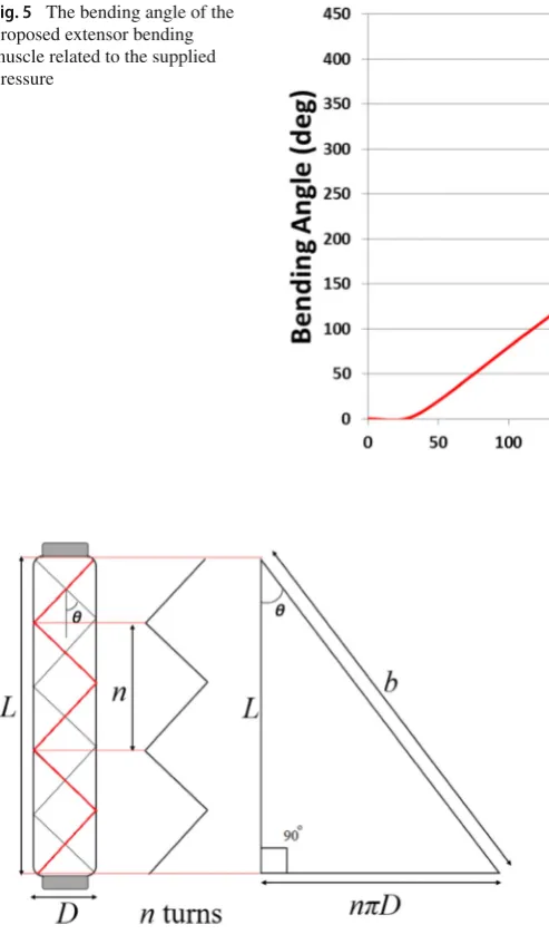
[image:6.595.78.512.52.420.2]Fig. 5 The bending angle of the proposed extensor bending muscle related to the supplied pressure
Fig. 6 The general geometry of pneumatic artificial muscles
energy state and this will cause extension of the artificial muscle.
As mentioned previously, the bending actuator is derived from an extensor actuator by reinforcing one side of the braided sleeve. In other words, that side of the sleeve angle is always at its maximum value and cannot extend in length. When increasing the supply pressure of the bending actua-tor, the free side only of the actuator will increase in length. Based on Fig.6, the nominal length of the bending muscle will be:
L =b cosθ (1)
and the actuator diameter:
D= b sinθ
nπ (2)
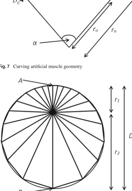
The analysis of the extensor bending artificial muscles is based on the following assumptions: the muscle main-tains a circular cross section during bending, the braid is formed from inextensible threads, there are no friction forces between the rubber tube and the braid or between the braid threads, and there are no elastic forces within the rubber tube. Figure 7illustrates the curving artificial muscle geometry, where Lois the actuator length on the fixed length side,Ln is the length of bending actuator on the free side, Dc is the bending actuator diameter,αis the curve angle of the actu-ator, ro is the inner radius andrn is the outer radius. The bending muscle lengthLcwill be the average length:
Lc=
Lo+Ln
2 (3)
The muscle diameter relevant to the inner and outer radii is:
Dc=rn−ro (4)
Using the equation for the length of an arc, the length of the two sides of the bending muscle will be:
Lo=b cosθmax=roα (5)
Ln=b cosθ=rnα (6)
The inner radiusroof the actuator curve can be determined by the maximum sleeve angle(θmax), which is a constant for
[image:7.595.170.544.52.275.2] [image:7.595.53.553.53.487.2] [image:7.595.55.302.54.478.2]Fig. 7 Curving artificial muscle geometry
Fig. 8 Radii inside bending actuator
sleeve angle will reduce around the circumference fromθon the outside edge of the curve (point A in Fig.8) toθmaxon
the inward edge of the curve (point B in Fig.8).
These sleeve angles will have an associated actuator diam-eter as illustrated in Fig.8. If it is assumed that the muscle cross section is a perfect circle, then the overall diameter will be the sum of the radii on the outside of the bendr1and inside
the bendr2, as shown in Fig.8. The bending muscle diameter
can be found from (2) as follows:
r1=
D1
2 =
bsinθ
2nπ (7)
r2=
D2
2 =
b sinθmax
2nπ (8)
Dc=r1+r2 (9)
Dc= b sinθ+b sinθmax
π (10)
However, if the thickness (tc) of the bladder and the sleeve is considered, the diameter equation will be:
Dc= b sinθ+b sinθmax
2nπ −2tc (11)
Now it is possible to develop the kinematic equations of the proposed bending actuator by using the above informa-tion, these equations describe the bending angleα, and the central axis length of the actuatorLcas follows:
By combining (4) in (6), we will have:
Ln=(Dc+ro)α (12)
Combining (5) and (6) in (12) produces the following equation:
Ln=
Dc+Lo
α
α=Dcα+Lo=b cosθ (13)
Based on (13) and (5) we can derive the bending angle as a function of braid anglesθandθmaxusing the following
equation:
α=b cosθ−b cosθmax
Dc (14)
Furthermore, the actuator length can be determined by substituting (5) and (6) in (3):
Lc=
b cosθmax+b cosθ
2 (15)
We now have equations describing the diameter and length of the bending muscle relative to the braid angle; this will be used in the next section to develop a model of actuator force.
3.2 Modelling the output force of the bending
actuator
Section3.1develops a kinematic analysis of the proposed bending actuator. However, if the actuator is to be utilized as part of an application, it is vital that its output force behaviour is also characterized. This has been achieved using the the-ory of the conservation of energy, as presented by Chou and Hannaford [26] for contracting PAMs. The input workWi n which exists in the PAM is in the form of supplied air pres-sure, which acts on the inner surface of the artificial muscle, and leads to changes in muscle volume. This can be demon-strated by the following equation:
dWin=
si
(P−Po)dli.dsi =(P−Po)
si
dli.dsi =P.dVc
[image:8.595.53.279.136.461.2]Fig. 9 The output force direction of the proposed bending actuator
wherePis the interior absolute gaseous pressure,Pois the environmental pressure (103.360 KPa at the time of testing), Pis the relative differential gaseous pressure,Siis the muscle total inner surface,dli is the internal surface displacement vector,dsi is the muscle area vector, andd Vcis the muscle volume change. Depending on the formula of volume of the cylinder:
V =πD
2L
4 (17)
the bending muscle volumeVcwill be:
Vc= πD
2
cLc
4 →Vc
= 1 32n2π
(b cosθmax+b cosθ)×
(b sinθ+bsinθmax−4nπtc)2
(18)
whereDcis the bending actuator diameter from (11) andLc is the central actuator length from (15).
The output workWout done when the proposed curving
actuator bends is associated with an increase in length of the muscleLcas a result of the muscle volume changing. This can be expressed by the following equation:
dWout=F.d Lc (19)
Figure9illustrates the output force direction of the pro-posed bending actuator.
Based on Energy Conservation Theory, the change in input work is equal to the change in output work:
dWin=dWout (20)
The proposed actuator output force can therefore be deter-mined from (16) and (19) as follows:
F =PdVc
dLc (21)
Differentiating the bending muscle volume and length with respect toθgives:
dVc dθ =
1 32n2π
×(2b2cosθ(cosθ+cosθmax)(b(sinθ+sinθmax)
−4nπtc)−b sinθ(b(sinθ+sinθmax)−4nπtc)2)
(22)
and:
dLc dθ =
−bsi nθ
2 (23)
The final mathematical model of the output force of the proposed extensor bending artificial muscle results from sub-stituting (22) and (23) in (21) as follows:
F = −2P
32n2πb sinθ
×(2b2cosθ(cosθ+cosθmax)(b(sinθ+sinθmax)
−4nπtc)−bsinθ(b(sinθ+sinθmax)−4nπtc)2)
(24)
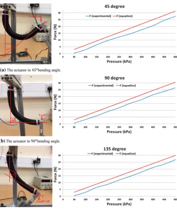
To validate this output force mathematical model of the bending muscles, we used the same muscle as in Fig.4. The muscle is placed in three positions (bending angles) to val-idate that the force model is correct at any bending angle. Figure10a shows the muscle at 45◦bending angle and the graphs of the theoretical output force from the model at the same bending angle with the experimental results of the out-put force of the proposed actuator. It is obvious from the two curves that there is a small gap between the theoreti-cal and the experimental output force at this position. For validation of this model, we placed the same muscle at 90◦ bending angle, as shown in Fig.10b. In this case, we also measured the theoretical and experimental output force of the proposed muscle, and the match between the two curves was as expected. Another validation was performed at a bend-ing angle of 135◦as shown in Fig.10c. In the results of these three experiments, the average error across all three curved angles was calculated to be 3.7 N. This represents an error of 12.05% of the maximum force generated by the proposed extensor bending artificial muscle.
[image:9.595.54.287.53.235.2] [image:9.595.300.546.76.288.2]Fig. 10 Three bending angles of the proposed actuator with their output force curves.aThe actuator in 45◦bending angle.b The actuator in 90◦bending angle.cThe actuator in 135◦ bending angle
been used to model contracting pneumatic muscles [27]. It is clear from Fig.10there is a dead zone at the lower pressure region than 50 kPa; that is because of the energy spend radi-ally expanding the rubber bladder before it makes contact with the braided sleeve.
4 Power augmentation soft glove
One of the drawbacks of most exoskeletons is that they have discrete joints, which must be effectively aligned to the wearer’s limb joints [28–30]. The wrong alignment may harm the wearer’s limb joints, and calibration is therefore required when another individual uses the exoskeleton. The main advantage of our novel bending actuator is that it does not have discrete joints, rather the whole actuator flexes. If the
muscle is placed at the back of a finger, when pressurized it will apply force to the whole back of the finger bringing about bending at the joints. In view of this idea, a soft exoskeleton glove was constructed. The power augmentation soft glove was constructed depending on our novel bending pneumatic artificial muscle, as shown in Fig. 11. Four bending actua-tors are reinforced (sewn) on the back surface of a traditional worker’s leather glove; one muscle for each finger except the little finger.
The supplied air for all muscles is controlled by a solenoid valve type MATRIX 3×3. The proposed soft exoskeleton glove has a weight of approximately 0.12 kg. The proposed exoskeleton sensing data are helpful to gather enough data about a hand motion to create appropriate assistance by the controller.
Fig. 11 The proposed exoskeleton
finger joints; one bend sensor to capture the bending angle of the root of the finger is named MP joint (metacarpopha-langeal Joint) and the others are for the PIP middle joint (proximal interphalangeal joint) and the DIP terminal joint (distal interphalangeal joint). An assumption of the con-troller is that all fingers bend together at the same time for full grasping movement; therefore, the index finger flex sen-sors provide the feedback of grasp movement angle of the hand. A force sensitive sensor (SEN-09375 with sensing area: 0.5) on the front side of the glove (on index fingertip) is also included. This sensor is attached to feedback the tactile press force of the index finger when grasping an object. Air pressure sensor is attached to the soft bending actuators for real-time feedback of the pressure inside the glove muscles. A significant problem of power augmentation and rehabil-itation exoskeletons is the grasping release movement. Due to power augmentation (when actuators are pressurized), the wearer may not be able to deliver enough force in the oppo-site direction to the actuated muscles to open the fingers or release the grasped object. For instance, if the wearer grasps an object with the exoskeleton’s support, he may not be able
[image:11.595.186.542.348.707.2]Fig. 13 The block diagram of the proposed position controller system
Fig. 14 The results of the neural network identifier and the error between the targets and outputs
to open his hand to release this object until the assisted mus-cles deflate, because his fingers’ force may be less than the assistive force.
Noritsugu, Takaiwa and Sasaki developed an exoskeleton for human hand grasping assistance without any information about a release movement [28]. Numerous hand exoskeletons such as [13,31–33], use manual control to release the grasps. Some rehabilitation hand exoskeletons such as [30,34,35] do not need controllers to release the grasp as movements are based on open-loop controllers for repetitive movements to grasp and release.
According to Kiminori et al. [29], the release movement was solved by estimating the grasping time needed before releasing the fingers (fixed time for all grasping types), which was not an effective solution, in light of the fact that there is no settled time for human hand grasping for one individual, and in this way it is difficult to gauge the time for numerous dif-ferent people. Other researchers [14,36,37] have attempted to solve this problem using electromyography (EMG) signals, however, this encountered problems because the features of human hand EMG signals for releasing a grip are similar in a wide range to the features of human wrist movement, so they
assumed that if the release grip signal occurred, the wrist was fixed and vice versa.
The proposed solution of the release movement problem is to leave the little finger without any assistance muscle. Instead of the assistive muscle, we placed a flex bend sensor size 4.4on the back of the little finger to provide the con-troller with real-time feedback on the little finger bending angle. As normal, when grasping an object, all fingers will bend, then the controller will start working. If we need to release the object, at first we release the little finger (because it is free of assisted force) then depending on the angle of the little finger (it will reach zero bend angle) the controller will understand it is a release movement then deflate all actuators.
5 The proposed control algorithm with
experimental results
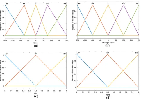
[image:12.595.56.542.212.395.2]Fig. 15 The membership functions for the inputs and outputs for the Fuzzy controller of the proposed position controller; whereNBNegative Big,
NSNegative Small,ZZero,PSPositive Small,PBPositive Big,ZFZero Fill,SFSmall Fill,BFBig Fill,ZVZero Vent,SVSmall Vent andBVBig Vent
of air. The classical control techniques are regularly created via simple models of the actuator functionality that fulfil the important assumptions and through the uncommon tuning of comparatively basic linear or nonlinear controllers.
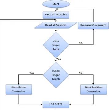
Figure12illustrates the proposed controller system flow chart. The initial state of the control system has vented all actuators (all bending muscles with zero air pressure). The next state is reading all sensors, flex bend sensors (on the index and little fingers), force sensitive sensor (on index fin-gertip) and the pressure sensor.
The first conditional block in the proposed algorithm is testing the little finger bending angle (if little finger bending angle=0) if there is no bend or return to the straight posi-tion, the release movement state will occur as explained in the previous section. If there is bending in the little finger, continue to the next condition. The second condition is to test the force sensitive sensor; whether the index fingertip is in contact with the object or not (the force > 0). If there is no force applied, start the position controller, and if there is a force, start the force controller. In other words, when the wearer needs to grasp an object, the wearer start to bend
his/her fingers to touch the object (the position controller system, in this case, actuate the muscles to follow the fingers until the fingers be in contact with the object then the con-troller system stop the position concon-troller and switch on the force controller depending on the index fingertip press force).
5.1 The position controller system
Fig. 16 Fuzzy controller rules surface for each fill and vent output of the proposed position controller
The computational burdens of the NN identifier and Fuzzy controller in the viewpoint of real-time implementation are acceptable because of the control system is simple and the NN is already trained. The control system is implemented by MATLAB, and there is not noticeable delay occurred in real-time interface operation.
5.1.1 The neural network identifier
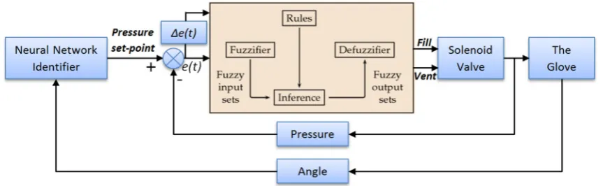
The first block of the proposed position control system is the neural network identifier. This block is used to generate the appropriate pressure set point for the position controller, depending on the online feedback signal of the index fin-ger bending angle. This neural network identifier is designed by the MATLAB neural network data fitting application. The experimental data from the relation between the
actu-ator bending angles and the amount of supplied pressure are used to design this identifier. The network includes one input layer, four hidden layers and one output layer. Bayesian Regularization [38] training technique is used to train the proposed neural network identifier. It is a network training technique that updates the weight and bias values according to Levenberg–Marquardt optimization; it minimizes a com-bination of squared errors and weights and then determines the correct combination so as to produce a network that gen-eralizes well. Figure14illustrates the results of this identifier and the error between the targets and outputs.
5.1.2 The fuzzy logic controller of the position controller
Fig. 17 The experimental results of the position controller system
Fig. 18 The proposed force controller
bending muscles. The desired pressure set point for each bending angle comes from the neural network identifier (real-time feedback signal). This Fuzzy controller has two inputs (error and change of error) and two outputs (fill and vent). As we used a MATRIX 3×3 solenoid valve to control the air flow by pulse-width modulation (PWM), the same valve output can fill and vent by applying two separate PWM signals. Based on this, the Fuzzy controller has two
Fig. 19 The membership functions for the inputs and outputs for the Fuzzy controller of the proposed force controller
Fig. 20 Fuzzy controller rules surface for each fill and vent output of the proposed force controller
controlled by the control system. Figure15shows the mem-bership functions of the inputs and outputs of the fuzzy controller.
There are five ranges for the input error and five ranges for the change in error, with the entire range being−200 to 200, because experimentally the proposed actuator when placed on the index finger reached its maximum angle at less than 200 KPa pressure. Likewise, three intervals for PWM fill
[image:16.595.55.543.449.570.2]Fig. 21 The experimental results of the force controller system
The proposed position controller is experimentally exam-ined. Figure17shows the experiment results of the controller at various bending angles. These six experiments were done by grasping cylindrical shape objects with different diame-ters to reach the grasping angles 38◦, 64◦, 90◦, 122◦, 144◦, and 170◦; they are represented in Fig.17a–f, respectively.
5.2 The force controller system
The proposed force controller is based on the assumption that the applied touch force from the fingertips to the grasped object is equal for all fingers depending on the index finger-tip force (see Fig.18). The main purpose of the proposed controller is to decrease the muscular effort of the wearer when grasping an object. The wearer needs only to apply press force on the object with the index fingertip (the wearer estimates the amount of this press pressure), after that rest-ing the wearer’s hand, and then the controller feeds back and calculates the maximum amount of this pressing force. This maximum press force will be added to the bent force (the spent force to reach the position at the moment of touch grasped object) to provide a force feedback signal to the controller system. The bent force is calculated by the kine-matic analysis equations of the bending actuator. Substitute the bending angle of the actuator (it is constant when fingers
in contact with the grasped object) in these equations to cal-culate the sleeve strain angleθ, and we have the amount of the pressure inside the actuators at the touching moment to calculate the bent force by using the proposed output force model in Eq.24. After adding the bending force to the maxi-mum touch force, we now have the desired force of the single fingertip and the strain angleθ; then we calculate the desired pressure set point of this pressing force, also by using Eq.24. By the same technique as the Fuzzy controller of the posi-tion controller system, we designed the Fuzzy controller of the force controller system. This Fuzzy controller has two inputs: error and change of error, with seven membership functions of each input; and two outputs: fill and vent, with four membership functions for each output, as shown in Fig.19. Figure20illustrates the Fuzzy controller rules sur-face of each fill and vent output in this controller.
Fig. 23 EMG signals analysis of grasping an object with 120◦bending angle of the human hand
bending angles were also tested with different press forces for validation, as shown in Fig.21c–f.
5.3 The validation of the proposed exoskeleton and
its controller
The validation of the proposed exoskeleton and its controller has been proven experimentally, as shown in Fig.22. Fig-ure 22a shows a human wearing the power augmentation exoskeleton and grasping to apply force on a load cell and the hand fingers bending angles was 120◦. Muscular effort, fatigue cause a corresponding increase in muscle activation amplitude measured with electromyography (EMG) [39]. Based on the previous research such as [14,28,32,33,40,41], there is a noticeable increase in EMG amplitude because of the increase in muscular efforts. EMG signals were monitored to demonstrate the muscular efforts during the experiment without wearing the exoskeleton as shown in Fig. 22b and with wearing the exoskeleton as shown in Fig.22c. The fingers’ bending angle was recorded as shown in Fig.22d. The desired pressure set points and the actual pressure inside the actuators are illustrated in Fig.22e. Fig-ure22f shows the index fingertip press force and the total applied force on the load cell.
We divided the experiment figures into six regions R1, R2, R3, R4, R5 and R6 to simplify what happened during the entire experiment:
• Region R1the wearer wears the exoskeleton with straight fingers without any movements.
• Region R2the wearer curls the fingers to touch the bar and the load cell, meanwhile the position controller is
active and the bending muscles follow the fingers until touch occurs at approximately 90◦bending angle; we can note the slightly increased muscular effort from the EMG signals because of the fingers’ movement.
• Region R3 the wearer touches the bar and the load cell and briefly presses with the index fingertip to apply force on the force sensitive sensor, meanwhile the force con-troller is working to reach the desired force; it is obvious from Fig.22c that at this region, the muscular effort is the maximum during the entire experiment because of the effort of the fingertip when pressing on the bar. The load cell force in Fig.22f is higher than the applied index fingertip force (approximately four times) because the applied force on the load cell comes from four fingers (index, middle, ring and thumb) with their assistive mus-cles.
• Region R4the wearer rests his muscles and the exoskele-ton performs the grasping function with the desired force and the proof of that is the muscular effort signals in Fig.22a in thisregion.
• Region R5 the wearer releases his little finger to the straight bending angle, then the release movement pro-cedure becomes active, venting all muscles to the zero pressure.
• Region R6the wearer’s fingers are straight again without any movement (as in R1) and the controllers standby for another movement.
Fig. 25 EMG signals analysis of grasping an object with 90◦bending angle of the human hand
to spend high efforts only at the beginning of grasping and pressing by its index fingertip on the object and after that the exoskeleton will apply the appropriate assistive force and the wearers hand takes rest (the lowest muscular efforts regions). Three statistical features from time domain are used in evaluation [42]. Time domain features can be implemented in real time. It usually used for detecting muscle contraction, muscle activity and onset detection. The three statistical fea-tures based on time domain are described as follows.
• Maximum amplitude Maximum amplitude (MAX) is defined as the peak amplitude of a signal. It is often used in areas where the measure and is a signal that is not sinu-soidal, which is the signal that swings above and below a zero value.
• Standard deviation Standard deviation (SD) measures the spread of data from the mean. In signal processing, SD represents noise and other interference. It is used in comparison to the mean. This leads to the term: signal-to-noise ratio (SNR), which is equal to the mean divided by the standard deviation. Better data mean a higher value for the SNR.
• Root mean squareRoot mean square (RMS) is another feature that popular in EMG signal analysis. RMS is defined as the square root of the mean over time of the square of the vertical distance of the graph from the rest state related to the constant force and non-fatiguing con-traction of the muscle. In most cases, it is similar to standard deviation method.
Figure23illustrates these three EMG features for Fig.22b, c. Figure23a shows the EMG signal analysis of the naked hand when grasping an object (experiment in Fig.22b), to
prove that the high muscular efforts are during completely grasping period (R3 and R4). Figure 23b shows the EMG signal analysis of a human wearing the power augmentation exoskeleton and grasping to apply force on a load cell (exper-iment in Fig.22c), to prove that the high muscular efforts are occurring only at pressing by the wearer index fingertip on the load cell (R3). This analysis supports our validation of the power augmentation glove by serving the aim of augmenting or assisting the wearer human hand during grasping objects. The same experiment and analysis were repeated at the fingers bending angles of approximately 90◦with different index fingertip pressing force, as shown in Figs.24and25.
6 Conclusion
The control system of this exoskeleton was created by hybridization between both cascaded position and force closed-loop intelligent controllers. The cascaded position controller is designed for the bending actuators to follow the fingers in their bending movements. The force controller was developed to control the grasping force augmentation. Validation of the control system with the exoskeleton has been done experimentally in this research. EMG signals were monitored to validate whether the proposed exoskeleton sys-tem decreased the muscular efforts of the wearer during the experiments.
Future work will seek to improve the mathematical model further by considering other losses such as rubber bladder impedance, the friction between the bladder and the braided sleeve, and the friction between the fibre threads in the braid. This will be done to improve the mathematical model and decrease the average percentage error. The controller system should also be developed to be more effective at decreasing the steady state errors with overshoots.
Acknowledgements The authors would like to thank the ministry of higher education/Iraq, University of Basrah, computer engineering department for providing scholarship support to the first author of this paper.
Open Access This article is distributed under the terms of the Creative Commons Attribution 4.0 International License (http://creativecomm ons.org/licenses/by/4.0/), which permits unrestricted use, distribution, and reproduction in any medium, provided you give appropriate credit to the original author(s) and the source, provide a link to the Creative Commons license, and indicate if changes were made.
References
1. Malcolm M (1996) Abstracting craft: the practiced digital hand. The MIT Press, Cambridge
2. Kazerooni H (1990) Human–robot interaction via the transfer of power and information signals. IEEE Trans Syst Man Cybern 20:450–463
3. Al-Fahaam H, Davis S, Nefti-Meziani S (2016) Power assistive and rehabilitation wearable robot based on pneumatic soft actuators. In: 2016 21st international conference on methods and models in automation and robotics (MMAR), pp 472–477
4. Al-Fahaam H, Davis S, Nefti-Meziani S (2016) Wrist rehabilitation exoskeleton robot based on pneumatic soft actuators. In: Interna-tional conference for students on applied engineering (ICSAE), pp 491–496
5. Gopura R, Bandara D, Kiguchi K, Mann GK (2016) Developments in hardware systems of active upper-limb exoskeleton robots: a review. Robot Auton Syst 75:203–220
6. Ergin MA, Patoglu V (2012) ASSISTON-SE: a self-aligning shoulder-elbow exoskeleton. In: 2012 IEEE international confer-ence on robotics and automation (ICRA), pp 2479–2485 7. Martinez JA, Ng P, Lu S, Campagna MS, Celik O (2013) Design
of wrist gimbal: a forearm and wrist exoskeleton for stroke reha-bilitation. In: 2013 IEEE international conference on rehabilitation robotics (ICORR), pp 1–6
8. Yamamoto I, Inagawa N, Matsui M, Hachisuka K, Wada F, Hachisuka A (2014) Research and development of compact wrist rehabilitation robot system. Bio-Med Mater Eng 24:123–128 9. Xiang KK, Hua PCJ, Rahman HA, Fai YC, Narayanan ALT, Ming
ESL (2015) Development of reconfigurable rehabilitation robot for post-stroke forearm and wrist training. Jurnal Teknologi 72:79–83 10. Chen S, Lien W, Wang W, Lee G, Hsu L, Lee K et al (2016) Assis-tive control system for upper limb rehabilitation robot. IEEE Trans Neural Syst Rehabil Eng 24(11):1199–1209
11. Otten A, Voort C, Stienen A, Aarts R, van Asseldonk E, van der Kooij H (2015) LIMPACT: a hydraulically powered self-aligning upper limb exoskeleton. IEEE ASME Trans Mechatron 20:2285– 2298
12. Vitiello N, Lenzi T, Roccella S, De Rossi SM, Cattin E, Giovac-chini F et al (2013) NEUROExos: a powered elbow exoskeleton for physical rehabilitation. IEEE Trans Robot 29:220–235 13. Polygerinos P, Wang Z, Galloway KC, Wood RJ, Walsh CJ (2015)
Soft robotic glove for combined assistance and at-home rehabili-tation. Robot Auton Syst 73:135–143
14. Polygerinos P, Galloway KC, Sanan S, Herman M, Walsh CJ (2015) EMG controlled soft robotic glove for assistance during activities of daily living. In: 2015 IEEE international conference on rehabil-itation robotics (ICORR), pp 55–60
15. Toya K, Miyagawa T, Kubota Y (2011) Power-assist glove operated by predicting the grasping mode. J Syst Des Dyn 5:94–108 16. Polygerinos P, Lyne S, Wang Z, Nicolini LF, Mosadegh B,
White-sides GM et al (2013) Towards a soft pneumatic glove for hand rehabilitation. In: 2013 IEEE/RSJ international conference on intel-ligent robots and systems (IROS), pp 1512–1517
17. Shen X (2010) Nonlinear model-based control of pneumatic arti-ficial muscle servo systems. Control Eng Pract 18:311–317 18. Kelasidi E, Andrikopoulos G, Nikolakopoulos G, Manesis S (2011)
A survey on pneumatic muscle actuators modeling. In: Industrial Electronics (ISIE), 2011 IEEE International Symposium, IEEE, pp 1263–1269
19. Tondu B, Lopez P (2000) Modeling and control of McKibben arti-ficial muscle robot actuators. IEEE Control Syst 20:15–38 20. Sárosi J, Gyeviki J, Véha A, Toman P (2009) Accurate position
control of PAM actuator in Lab VIEW environment. In: 7th inter-national symposium on intelligent systems and informatics, 2009. SISY’09, pp 301–305
21. Sárosi J, Gyeviki J (2009) Experimental setup for the positioning of humanoid upper arm. Comput Methods Biomech Biomed Eng 13:11–18
22. Hosovsky A, Novak-Marcincin J, Pitel J, Borzikova J, Zidek K (2012) Model-based evolution of a fast hybrid fuzzy adaptive con-troller for a pneumatic muscle actuator. Int J Adv Robot Syst 9:673–681
23. Nuchkrua T, Leephakpreeda T (2013) Fuzzy self-tuning PID con-trol of hydrogen-driven pneumatic artificial muscle actuator. J Bionic Eng 10:329–340
24. Qian J, Huang J, Ri S (2015) Adaptive fuzzy sliding mode con-trol for pneumatic muscle actuator. Chin Autom Congress (CAC) 2015:431–436
25. Sun D, Yan B, Han B, Song Y, Zhang X (2016) Vibration charac-teristic simulation of a pneumatic artificial muscle damping seat. J Low Freq Noise Vib Active Control 35:39–51
26. Chou C-P, Hannaford B (1996) Measurement and modeling of McKibben pneumatic artificial muscles. IEEE Trans Robot Autom 12:90–102
27. Davis S, Tsagarakis N, Canderle J, Caldwell DG (2003) Enhanced modelling and performance in braided pneumatic muscle actuators. Int J Robot Res 22:213–227
conference on mechatronics and machine vision in practice, 2008. M2VIP 2008, pp 539–544
29. Kiminori T, Miyagawa T, Kubota Y (2011) Power-assist glove operated by predicting the grasping mode. J Syst Des Dyn 5:94–108 30. Yap HK, Lim JH, Nasrallah F, Goh JC, Yeow RC (2015) A soft exoskeleton for hand assistive and rehabilitation application using pneumatic actuators with variable stiffness. In: 2015 IEEE international conference on robotics and automation (ICRA), pp 4967–4972
31. Noritsugu T, Yamamoto H, Sasakil D, Takaiwa M (2004) Wearable power assist device for hand grasping using pneumatic artificial rubber muscle. In: SICE 2004 annual conference, pp 420–425 32. Noritsugu T (2005) Pneumatic soft actuator for human assist
tech-nology. In: Symposium on fluid power
33. Tadano K, Akai M, Kadota K, Kawashima K (2010) Develop-ment of grip amplified glove using bi-articular mechanism with pneumatic artificial rubber muscle. In: 2010 IEEE international conference on robotics and automation (ICRA), pp 2363–2368 34. Polygerinos P, Lyne S, Wang Z, Nicolini LF, Mosadegh B,
White-sides GM, Walsh CJ (2013) Towards a soft pneumatic glove for hand rehabilitation. In: Intelligent Robots and Systems (IROS), 2013 IEEE/RSJ International Conference, pp 1512–1517 35. Polygerinos P, Galloway KC, Savage E, Herman M, O’Donnell
K, Walsh CJ (2015) Soft robotic glove for hand rehabilitation and task specific training. In: 2015 IEEE international conference on robotics and automation (ICRA), pp 2913–2919
36. Kadowaki Y, Noritsugu T, Takaiwa M, Sasaki D, Kato M (2011) Development of soft power-assist glove and control based on human intent. J Robot Mechatron 23:281
37. Sasaki D, Noritsugu T, Takaiwa M, Konishi H (2014) Control method based on EMG for power assist glove using self-organizing maps. Int J Autom Technol 8:177–85
38. Demuth HB, Beale MH, De Jess O, Hagan MT (2014) Neural Network Design. Martin Hagan
39. Graham RB, Wachowiak MP, Gurd BJ (2015) The assessment of muscular effort, fatigue, and physiological adaptation using EMG and wavelet analysis. PLoS ONE 10:e0135069
40. Sasaki D, Noritsugu T, Takaiwa M (2005) Development of active support splint driven by pneumatic soft actuator (ASSIST). In: Pro-ceedings of the 2005 IEEE international conference on robotics and automation, 2005. ICRA 2005, pp 520–525
41. Kadota K, Akai M, Kawashima K, Kagawa T (2009) Develop-ment of Power-Assist Robot Arm using pneumatic rubbermuscles with a balloon sensor. In: The 18th IEEE international symposium on robot and human interactive communication, 2009. RO-MAN 2009, pp 546–551
42. Daud WMBW, Yahya AB, Horng CS, Sulaima MF, Sudirman R (2013) Features extraction of electromyography signals in time domain on biceps Brachii muscle. Int J Model Optim 3:515
![Fig. 1 Human upper-limb anatomy [5]](https://thumb-us.123doks.com/thumbv2/123dok_us/8671608.872648/3.595.310.538.57.288/fig-human-upper-limb-anatomy.webp)