International Journal of Emerging Technology and Advanced Engineering
Website: www.ijetae.com (ISSN 2250-2459, ISO 9001:2008 Certified Journal, Volume 6, Issue 5, May 2016)
45
Design and Analysis of Various Bluff Objects for
Vortex flow meters
T. Milinda Purna
1, L. Aarya
2, K. Lakshmi Nageswari
31Assistant Professor, Department Of Electronics & Instrumentation, Sree Vidyanikethan Engineering College 2,3Department of Electronics & Instrumentation Sree Vidyanikethan Engineering College
Abstract— Vortex flow meters are standard devices to
measure flow rates of fluids (liquids, gases, steam and cryogenic fluids) in industrial applications. The working principle of vortex flow meter is based on Karman vortex street phenomenon. Bluff body is the key component in a vortex flow meter because the stability of generated vortex street depends on the shape and geometric parameters of the bluff body. Frequency of the shedding vortices is used to measure the flow rate. A smooth bluff body shape may not generate stable and sharp vortices. In this paper the flow over various bluff bodies in a pipe has been analyzed using COMSOL Multiphysics software to study the effect of body shape on pressure loss and velocity, by determining lift coefficient and drag coefficient. The experiments were done with different bluff bodies with and without using splitter plate. Using splitter plate will help in permanent pressure loss. We can develop many applications including energy harvesting by installing piezoelectric sensors on the bluff bodies.
Keywords— Vortex flow meters, Bluff body, COMSOL Multiphysics, lift coefficient, drag coefficient.
I. INTRODUCTION
The vortex flow meters uses the phenomenon called ―vortex shedding‖, that occurs when a fluid flows against an obstruction, termed a bluff body. The vortices are formed alternatively on both sides of the bluff body at a frequency which is proportional to the mean flow velocity in the pipe. Vortex flow meters are good choice to work under hazardous atmosphere. Vortex flow meters have been used for industrial purpose since 1970, but the bluff bodies with good signal to noise ratio were developed recently. The use of these sensors rapidly diffused due to the good characteristics of sensitivity and linearity in a large of flow rate. It is possible to measure flow rates of
Fluids at temperatures from -2000C to +4000C and pressures up to 300 bar; this range is about six times greater than orifice methods. Accuracy of measurement is not influenced by pressure, temperature, density and viscosity variations.
To establish the shedding characteristics in non pulsating flow, here we examine the shedding behaviour of the various geometries in a 2D uniform study flow. In particular the variation of lift and drag coefficients with different densities and for similar area of cross section was examined. The Reynolds number Re in all cases is set at 100, so that the flow is laminar.
A. Vortex flow meter measuring principle:
Vortex flow meters also known as vortex shedding flow meters or oscillatory flow meters consists of bluff body immersed in fluid causes vortices to be shed downstream of the bluff body. The vortices will be shed on alternative sides of the bluff body and the frequency is proportional to the flow velocity as shown in equation (1).
f=s.v/d --- (1)
s=strouhals number
f=frequency
v=average flow velocity
d=width of bluff body
B. Methods for detecting vortices:
1) Detecting vortices with pressure transducer: One way to calculate vortex frequency is to use pressure transducers. There is a change in pressure of flow due to vortex shedding. Pressure transducer will detect the pressure fluctuations and calculates the vortex frequency.
2) Detecting vortices with ultrasonic transducer: The vortices formed will affect the phase and frequency of ultrasonic signal. We will place ultrasonic transducer in the downstream of the bluff body and measurements are perpendicular to the fluid flow.
International Journal of Emerging Technology and Advanced Engineering
Website: www.ijetae.com (ISSN 2250-2459, ISO 9001:2008 Certified Journal, Volume 6, Issue 5, May 2016)
46 C. Drag coefficient (CD): It is a dimensionless quantity that is used to quantify the drag or resistance of an object in a fluid environment, such as air or water or any other medium. It is an unavoidable consequence of an object moving through a fluid. Drag coefficient is directly proportional to the area of the object, doubling the area doubles the drag. In addition the amount of drag generated by an object depends on the size of the object. The lift and drag coefficients are given in equations (2) and (3).
CD=2FD/ρU2mean.L --- (2)
D. Lift coefficient (CL): Lift is the force generated perpendicular to the direction of travel for an object moving through a fluid. It is a dimensionless coefficient that relates the lift generated by a bluff body to the fluid density around the body, the fluid velocity and an associated reference area. The lift coefficient can be calculated as:
CL=2FL/ρU2mean.L --- (3)
Where, FD and FL are drag and lift forces,
ρ is the fluid density Umean is the mean velocity
L is the characteristic length, i.e. cylinder’s radius
II. SIMULATION
The simulation we have carried in this paper is done with the help of COMSOL Multiphysics. It is simulation software based on finite element method. It can simulate many physical and engineering applications, and especially coupled phenomenon or multiphysics. It is dedicated to various domains like electrical, mechanical, fluid flow and chemical applications. Additional interfacing products connect your COMSOL Multiphysics simulation with technical computing, CAD and ECAD software. Here we used a version of COMSOL 5.0.
We use laminar inlet fluid flow in this simulation. To initiate the vortex production, the flow needs some kind of asymmetry in the symmetric velocity inlet profile. The asymmetry is nothing but the bluff body. The flow around in a cylinder is a common point of reference test for CFD algorithms. The procedure involved in the simulation starts with selecting the physics, which is laminar flow in the fluid flow. Here we perform the simulation in 2D by selecting from model wizard window. Next we select the time-dependent study and then provide the required parameters. We choose step function for plotting and also provide the parameters and location for the function.
[image:2.612.332.571.189.549.2]Then we build a rectangle in the geometry section with the diameter of 0.4m.
Table I
Dimensions Of Bluff Bodies
Later we choose our bluff bodies to be inserted in the flow meter such as circle, triangle, rectangle, square, ellipse etc, and specify their diameters and dimensions as per our requirements as shown in Table I. Then we choose the difference operation in Booleans and partitions for subtraction of the bluff body from the rectangle in order to provide some disturbance during flow. Then we choose the blank material and in the contents section, and enter the density and dynamic viscosity values. Then in the laminar flow section we select the inlet and outlet boundaries of the flow meter, further in the inlet settings window we provide the velocity equation. Then the component is meshed in finer element size.
S. no
Type of
the
shape
Area
Dimensions in
m
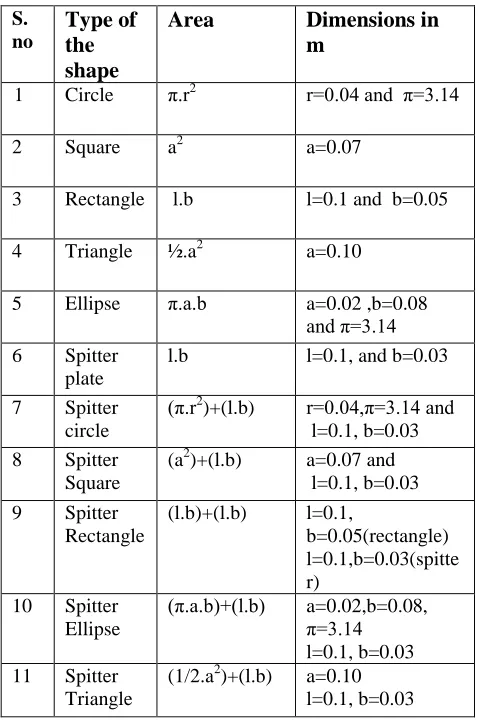
11 1 Circle π.r2 r=0.04 and π=3.14
2 Square a2 a=0.07
3 Rectangle l.b l=0.1 and b=0.05
4 Triangle ½.a2 a=0.10
5 Ellipse π.a.b a=0.02 ,b=0.08 and π=3.14 6 Spitter
plate
l.b l=0.1, and b=0.03
7 Spitter circle
(π.r2
)+(l.b) r=0.04,π=3.14 and l=0.1, b=0.03
8 Spitter Square
(a2)+(l.b) a=0.07 and l=0.1, b=0.03
9 Spitter Rectangle
(l.b)+(l.b) l=0.1,
b=0.05(rectangle) l=0.1,b=0.03(spitte r)
10 Spitter Ellipse
(π.a.b)+(l.b) a=0.02,b=0.08, π=3.14 l=0.1, b=0.03 11 Spitter
Triangle
International Journal of Emerging Technology and Advanced Engineering
Website: www.ijetae.com (ISSN 2250-2459, ISO 9001:2008 Certified Journal, Volume 6, Issue 5, May 2016)
[image:3.612.321.568.238.382.2]47 Later in the model builder window we select the time dependent study and enter the specified ranges in the settings. We select the time dependent solver1 under the solution 1, and choose intermediate steps taken by solver under time stepping function. Then we compute the model. Further in the results window, we select the particle tracing with mass plot in the velocity section. In the mass and velocity settings type the equation in the mass section and range in the particle positioning section. Then further define the parameters in the release section and colouring and style section. Later we click plot in the velocity (spf) toolbar. On the results toolbar we select the evaluation dataset and choose the boundaries of the bluff body in the geometry entity selection. Then for plotting in 1D plot group we choose point graph and provide the expressions in the settings window. We find the results as following figures. The dimensions details of the bluff bodies are furnished below in the tabular column.
Table II Different Densities
The area of all the bluff bodies remains same throughout the simulation i.e. 0.005m. We have carried out the simulation in three different densities they are Aerogel, water, Liquid hydrogen, their densities are stated in Table II. The flow meter has wide range of applications in different densities. The spitter plate attached to the bluff bodies drops the pressure to a wide extent resulting in various advantages. The spitter plate area remained same for all the bluff bodies’ i.e. 0.003m.
III. RESULTS AND DISCUSSION
Hence we have computed for various shapes in three densities, and found the best shapes for each density. We have considered the pressure loss and also lift and drag coefficients for concluding the best shapes
Best shapes with respect to PRESSURE DROP are: Splitter Triangle- Aerogel density
Square –Water density
Circle- Liquid Hydrogen density
By considering the pressure loss coefficient, splitter triangle bluff body is found to be the best shape in aerogel density.
[image:3.612.327.564.517.692.2]Best Shapes with respect to Lift and Drag coefficients are:
Table III Best Shapes
S.no Shape Drag
coefficient Lift coefficient
Density
1. Splitter Rectangle
7.5 11.5 Liquid
Hydrogen
2. Splitter Triangle
3.0 3.6 Water
3. Splitter Rectangle
6.8 11 Water
As we can see in the above table Splitter Rectangle and Splitter Triangle are found to be best shapes in overall analysis as in the above Table III, when lift and drag coefficients are considered.
For an ideal bluff body the drag coefficient should be less than the lift coefficient. As we can see in the table these both shapes have less drag coefficient than lift coefficient. Splitter Rectangle is considered to be the best shape in Liquid hydrogen and water densities. Splitter triangle is found to be the best shape in water density. Following are the results of the above mentioned shapes.
S.no Material Density
(kg/m3)
1 Aerogel 1
2 Water 997.047
International Journal of Emerging Technology and Advanced Engineering
Website: www.ijetae.com (ISSN 2250-2459, ISO 9001:2008 Certified Journal, Volume 6, Issue 5, May 2016)
48
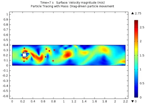
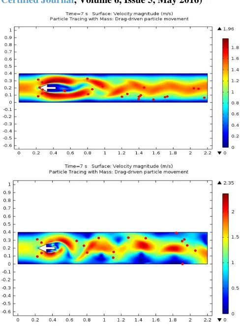
fig (a): Velocity plots of square, circle and splitter rectangle bluff bodies
fig (b): Velocity plots of splitter triangle in water, Aerogel and liquid hydrogen densities
IV. CONCLUSION
[image:4.612.329.573.124.456.2] [image:4.612.54.298.144.463.2]International Journal of Emerging Technology and Advanced Engineering
Website: www.ijetae.com (ISSN 2250-2459, ISO 9001:2008 Certified Journal, Volume 6, Issue 5, May 2016)
49 But the vortex flow meters requires a body shape with sharp corners to generate stable vortex shedding frequency. It is found that bluff body geometry has significant effect on the shedding characteristics. Based on our reference papers we have computed bluff bodies and found new things and also reduced the pressure loss by placing a splitter plate as a tail to the bluff body. Energy harvesting application can be done by placing a piezoelectric strip on the bluff body. Here we can generate voltage and use this application in many fields. Hence the overall analysis has done on the various bluff bodies with and without splitter plate, and found that splitter rectangle and splitter triangle are found to be the best shapes. Hence all these bluff bodies are used in all the vortex flow meter applications like, Custody transfer of natural gas metering, steam measurement applications, flow of liquid suspensions, general water applications, Liquid chemicals and pharmaceuticals, food processing industries, oil and gas industries etc.
REFERENCES
[1] Mujaferija s,peric M & seidi V,computation of flow around circular
cylinder in a channel, Internal Report, Institute fiir
shiffbau,University of Hamburg, 1995.
[2] Swaroop A, Design of vortex flow meter, M.Tech. Thesis, IIT Delhi,
1990. Singh S N, seshadri V &swaroop A, Effect of size and shape of the bluff body on strouhal number in pipe flow, 20th Nation conf on FMFF, palaghat, 1993.
[3] BEARMAN, P.W. and TRUEMAM, D.M. ―An investigation of the
flow around rectangular cylinders‖, Aeronautical Quarterly, 229-237, 1992.
[4] LANEVILLE A.and YONG, L.Z ―Mean flow patterns around
two-dimensional rectangular cylinders and their interpretation‖, J.Wind Eng.&Indust.Aero.14,387-398,1983.
[5] OKAJIMA, A. ―Numerical analysis of the flow around an oscillating
cylinder‖ in flow induced vibration, Balkema, Rotterdam pp.159-166, 1995.
[6] STFGGEL, N.,‖A Numerical Investigation of the Flow Around
Rectangular cylinders‖, ph.D.Thesis, university of surrey, 1998.
[7] Kalkhof H.G.: Influence of the bluff body shape on the measurement