On In-situ Methodologies for the
Characterisation and Simulation of
Vibro-Acoustic Assemblies
Ph.D. Thesis
Acoustics Research Centre, University of Salford Greater Manchester
Author
Joshua W R Meggitt
Supervisor
Prof. Andy T Moorhouse
A thesis submitted in partial fullment of the requirements
for the degree of Doctor of Philosophy
Declaration of Authorship
I, Joshua W R Meggitt, declare that this Thesis titled, `On In-situ Methodologies for the Characterisation and Simulation of Vibro-Acoustic Assemblies' and the work presented in it are my own. I conrm that:
- This work was done wholly or mainly while in candidature for a research degree at this University.
- Where any part of this thesis has previously been submitted for a degree or any other qualication at this University or any other institution, this has been clearly stated.
- Where I have consulted the published work of others, this is always clearly attributed.
- Where I have quoted from the work of others, the source is always given. With the exception of such quotations, this thesis is entirely my own work.
- I have acknowledged all main sources of help.
- Where the thesis is based on work done by myself jointly with others, I have made clear exactly what was done by others and what I have contributed my-self.
Signed:
Date:
Be excellent to each other, and party on dudes"
Abstract
A drive towards leaner engineering has seen the use of physical prototypes become a limiting factor in the development of new products. Consequently, alternative pro-totyping methods are of interest. With their ability to reduce cost, accelerate time to market, and optimize products to higher levels of performance and reliability, vir-tual methods oer an attractive alternative. Methods for virvir-tual prototyping with respect to visual design and engineering (i.e CAD and CAE) are particularly well developed. Unfortunately, the same cannot be said in the realm of acoustics. Al-though numerical methods, such as nite and boundary element analysis, are able to predict, with some accuracy, the passive properties of simple assembly components, they currently lack the ability to accurately model more complex vibro-acoustic com-ponents, for example vibration sources and their associated vibratory mechanisms. Consequently, the adoption of any virtual acoustic prototyping (VAP) methodol-ogy will require some element of experimental work. As such, this Thesis concerns the development and implementation of experimental methods for the independent characterisation of assembly components, with particular emphasis on in-situ ap-proaches. The methods discussed in this work will focus on the determination of active and passive sub-structure properties that may be recombined virtually within a dynamic sub-structuring framework so as to construct a VAP. A well constructed VAP will allow for an engineer to `listen' to a product without it having to phys-ically exist. With the growing importance of product sound quality, this oers a considerable advantage, particularly in the early stages of product development. Work begins by developing an in-situ method for the independent characterisation of resilient coupling elements. The approach holds a number of advantages over current methods as it may be applied to arbitrary structures and over a wide frequency range. In order to provide a exible and workable method that may be used in a practical scenario three experimental extensions are provided. These extensions concern; the nite dierence approximation for rotational degrees of freedom, the round trip identity for remote measurement positions, and generalised transmissibility for the use of operationally determinable quantities. Experimental studies show that the proposed method, and its extensions, are capable of determining the independent
passive properties of coupling elements from a range of dierent assembly types with good accuracy.
The in-situ characterisation approach goes on to form the basis of a novel in-situ decoupling procedure which is shown to accurately determine the independent free interface frequency response functions (FRFs) of resiliently coupled source and re-ceiver sub-structures. The decoupling procedure provides a convenient alternative to the free suspension of a sub-structure whilst providing a number of potential benets, for example, characterisation whilst under representative mounting condi-tions. The approach is validated experimentally and used to decouple both single and multi-contact resonant assemblies with great success.
The in-situ blocked force approach is re-introduced to the reader as a method for independently characterising the active component of a source sub-structure. Meth-ods for assessing uncertainties involved are also discussed. The blocked force method is subsequently extended so as to allow for an estimate of uncertainties to be made. The concept of error propagation is investigated and an experimental study pre-sented. This study is aimed at providing an example of the in-situ blocked forces application, whilst validating the proposed measure of uncertainty.
Acknowledgements
Firstly, I would like to express my immeasurable gratitude towards my supervisor Prof. Andy Moorhouse for his continuous support, patience and motivation. It would be by no means an understatement to say that I could not have asked for a better supervisor and mentor for my PhD studies. I am also especially indebted to Dr. Andy Elliot whose guidance, encouragement, and insightful comments have been indispensable.
Also in need of special thanks are the remaining members of sta at the Acoustic Research Center. Furthermore, I would also like to acknowledge with much ap-preciation the role of all those involved in the Research projects I was employed on throughout my PhD studies, notably those residing at Dyson UK, The Boeing Company and The University of Liverpool.
A special thanks must also be paid to my fellow G10/G11 post-graduates. The past 3/4 years has been awash with enjoyable conversions, snacks, boardgames and beers, and it goes without saying that my time as a post-graduate would certainly have been a lot less enjoyable without you all.
Beyond the realms of the Newton Building there are a few people whose support and friendship I would like to acknowledge; Tim, Kate, Phil, and all my friends back home. I must also pay a special thanks to John Saxton, for it was he who rst introduced me to acoustics and unknowingly set me on this delightful path.
On a more personal note I would like to thank my love, Rosie, for her endless support and patience. It is safe to say that forgetting to wear shoes that night was the best mistake I ever made. Last but not the least, I must thank my family; Mum, Dad and Jack. Without their love and encouragement I would certainly not be in the position I am today, and for that I am eternally grateful.
Contents
Abstract iii
Contents v
List of Figures vii
List of Tables viii
Author Publications ix
Symbols x
Foreword xii
I Introduction and Literature Review
1
1 Introduction 2
1.1 Research Context and the VAP Approach . . . 2
1.2 Thesis Topics, Aims and Objectives . . . 7
1.3 Thesis Outline . . . 8
2 Literature 9 2.1 Denitions . . . 9
2.1.1 Mobility . . . 9
2.1.2 Impedance . . . 10
2.1.3 Degrees of Freedom & LTI Systems . . . 11
2.2 Source Characterisation . . . 13
2.3 Dynamic Sub-structuring . . . 19
2.3.1 Sub-structure Decoupling . . . 22
2.4 Isolator Characterisation . . . 22
II Coupling Elements
28
3 Characterisation of Resilient Elements 29 3.1 In-situ Characterisation of Coupling Elements . . . 293.2 Theoretical Development . . . 30
3.3 Numerical Validation . . . 37
3.4 Experimental Application . . . 42
3.4.1 Single Contact . . . 43
Mass-Isolator-Mass . . . 43
Transmissibility Validation . . . 49
Mass-Isolator-Plate . . . 50
Beam-Isolator-Plate . . . 53
3.4.2 Multiple Contact . . . 58
Beam-Isolator(2)-Plate . . . 58
3.5 Concluding Remarks . . . 63
4 Experimental Extensions 64 4.1 Rotational Degrees of Freedom . . . 64
4.1.1 Finite Dierence Approach . . . 66
4.1.2 Numerical Validation . . . 69
4.1.3 Experimental Validation . . . 71
4.1.3.1 Single Contact . . . 71
Mass-Isolator-Mass . . . 71
4.2 Extension to Remote Measurement Positions . . . 73
4.2.1 Dual Interface Round Trip . . . 75
4.2.2 Remote In-situ Characterisation . . . 76
4.2.2.1 Remote Partial Interface Method . . . 76
4.2.2.2 Remote Full Interface Method . . . 78
4.2.3 Experimental Validation . . . 79
4.2.3.1 Single Contact . . . 79
Beam-Isolator-Plate . . . 79
4.2.3.2 Multiple Contact . . . 84
Beam-Isolator(2)-Plate . . . 84
4.3 Operational Characterisation via the Generalised Transmissibility . . 88
4.3.1 Generalised Transmissibility Concept . . . 89
4.3.2 Operational Dynamic Transfer Stiness . . . 92
4.3.3 Experimental Validation . . . 94
4.3.3.1 Single Contact . . . 94
Beam-Isolator-Plate . . . 94
4.3.3.2 Multiple Contact . . . 97
Beam-Isolator(2)-Plate . . . 97
4.4 Concluding Remarks . . . 100
III Source and Receivers
102
5 In-Situ Sub-structure Decoupling 103 5.1 Sub-structure Decoupling . . . 1035.2 In-situ Decoupling Theory . . . 106
5.3 Experimental Investigation . . . 112
5.3.1.1 Mass-Isolator-Plate . . . 113
5.3.1.2 Beam-Isolator-Plate . . . 116
5.3.2 Multiple Contact . . . 121
5.3.2.1 Beam-Isolator(2)-Plate . . . 121
5.4 Concluding Remarks . . . 125
6 Blocked Force Characterisation 126 6.1 Independent Source Characterisation . . . 126
6.2 Blocked Force Theory . . . 128
6.2.1 Impedance Formulation . . . 129
6.2.2 Mobility Formulation . . . 132
6.2.3 Blocked Force Determination . . . 134
6.2.3.1 Experimental Considerations . . . 136
6.2.3.2 Post Processing for Auralisation . . . 138
6.3 Accounting for Uncertainty . . . 140
6.3.1 On-board and Transferability Validation . . . 140
6.3.1.1 Articial Excitation . . . 142
6.3.2 Sample Space Approach - Expected Value and Standard De-viation . . . 142
6.3.2.1 Nature of the Sample Space Uncertainty . . . 145
6.3.2.2 Alternative Uncertainty Approach . . . 147
6.3.2.3 Propagation of Uncertainty . . . 150
6.4 Experimental Validation . . . 153
6.4.1 Resiliently Coupled Source and Receiver . . . 154
6.4.1.1 Articial Excitation . . . 155
Blocked Forces and Standard Deviations . . . 156
On-board Validation . . . 163
6.4.1.2 Operational Excitation . . . 167
Blocked Forces and Standard Deviations . . . 168
On-board Validation . . . 171
Transferability Validation . . . 174
6.5 Concluding Remarks . . . 177
IV Experimental Case Study and Conclusions
178
7 Case Study 179 7.1 Building Blocks . . . 1797.2 Dynamic Sub-Structuring . . . 180
7.2.1 Numerical Example: Beam-Beam . . . 182
7.3 Experimental Case Study . . . 187
1a) Passive Source Characterisation . . . 189
1b) Active Source Characterisation . . . 192
2) Resilient Coupling Element Characterisation . . . . 192
4) Dynamic Sub-Structuring . . . 194
5) Operational Prediction . . . 201
7.4 Concluding Remarks . . . 209
8 Conclusion 210
V Appendices and Bibliography
215
Appendices 216 A Regularisation . . . 216B Matrix Identities . . . 219
C Summary of Assembly Details . . . 220
D Matrix Reduction . . . 221
E Experimental Case Study - IOA Conference Proceeding Manuscript . 222 E.1 Introduction . . . 222
E.2 Source Characterisation: Blocked Force Method . . . 223
E.3 Dynamic Sub-structuring: Impedance Approach . . . 226
E.4 In-Situ Isolator Characterisation . . . 228
E.5 Case-Study . . . 229
E.6 Conclusion . . . 232
List of Figures
1.1 Diagrammatic representation of a general VAP problem. . . 6 2.1 Cartesian co-ordinate system and notation of forces and velocities. . . 12 3.1 Schematic of an arbitrary source-isolator-receiver system. . . 31 3.2 Forces contributing to the velocity of interface c1 (as in Equation 3.6). 32
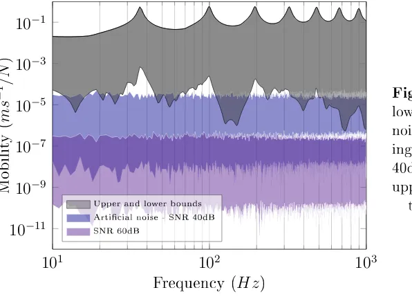
3.3 Graphical depiction of the numerical simulation carried out. . . 37 3.4 The upper and lower bounds of the articial noise matrix N
corre-sponding to SNRs of 60dB and 40dB, compared against the upper and lower bounds of the mobility matrixY. . . 40 3.5 Translational transfer impedance obtained via numerical simulation.
Solid blue line is the exact transfer impedance obtained from I whilst uncoupled. . . 41 3.6 Diagrammatic representation of the mass-isolator-mass test rig. Red
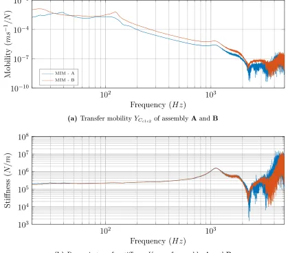
arrows correspond to the direction and position of the applied forces, whilst blue arrows indicate the positive direction of the measured accelerations. . . 45 3.7 Dynamic transfer stiness and transfer mobility measurements made
on assemblies A and B (see Table 3.2). . . 46 3.8 Dynamic transfer stiness and transfer mobility measurements made
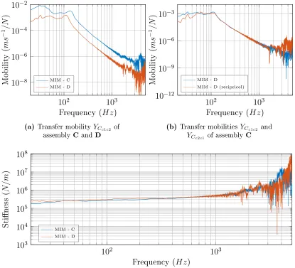
on assemblies C and D (see Table 3.2). Low level excitation atc2 was
used to avoid introducing non-linearities. . . 47 3.9 Dynamic transfer stiness and transfer mobility measurements made
on assemblies C and D (see Table 3.2). High level excitation at c2
was used to exaggerate non-linearities resulting from large dierence in mass behaviours. . . 48 3.10 Measured and predicted transmissibilities of assembly B obtained
us-ing a dynamic stiness determined from assembly A. . . 50 3.11 Diagrammatic representation of the mass-isolator-plate test rig, E.
Red arrows correspond to the direction and position of the applied forces, whilst blue arrows indicate the positive direction of the mea-sured accelerations. . . 51 3.12 Dynamic transfer stiness and transfer mobility measurements made
on assemblies C and E (see tables 3.2 and 3.3). . . 52 3.13 Diagrammatic representation of the beam-isolator-plate test rig, F,
showing both full and partial interface measurement set-ups. Red arrows correspond to the direction and position of the applied forces, whilst blue arrows indicate the positive direction of the measured accelerations. . . 54
3.14 Dynamic transfer stiness and transfer mobility measurements made on assemblies C and F using partial interface approach. . . 55 3.14 (Continued) Dynamic transfer stiness and transfer mobility
mea-surements made on assemblies C and F using partial interface approach. 56 3.15 Diagrammatic representation of the beam-isolator(2)-plate test rig,
G, for full and partial interface measurements. Red arrows correspond to the direction and position of the applied forces, whilst blue arrows indicate the positive direction of the measured accelerations. . . 60 3.16 Dynamic transfer stiness and transfer mobility measurements made
on assemblies C and G (see tables 3.2 and 3.5) using full and partial interface approach. . . 61 3.16 (Continued) Dynamic transfer stiness and transfer mobility
mea-surements made on assemblies C and G (see tables 3.2 and 3.5) using full and partial interface approach. . . 62 4.1 Force and velocity positions for nite dierence approximation. . . 66 4.2 Rotational transfer impedance Z˜Iψ
2τ1 obtained via numerical
simu-lation using nite dierence approach. Solid blue line is the exact transfer impedance obtained from beam Iwhilst decoupled. . . 70 4.3 Dynamic transfer stiness and transfer mobility measurements made
on assemblies. . . 72 4.4 Mobility paths for the round trip and `broken' round trip terms of
Equation 4.24. . . 77 4.5 Diagrammatic representation of the beam-isolator(2)-plate test rig,
G. Red arrows correspond to the direction and position of the ap-plied forces, whilst blue arrows indicate the positive direction of the measured accelerations. . . 80 4.6 Contact interface mobility matrix determined from assembly F (see
tables 3.4) using direct and round trip methods. For the round trip case both determined and over-determined results are presented. . . . 81 4.7 Dynamic transfer stiness'KIc1c2 determined from assemblies C and F
(see tables 3.2 and 3.4) using direct and remote method (see Sections 3.2 and 4.2.2). For remote cases both determined and over-determined results are presented. . . 83 4.8 Diagrammatic representation of the beam-isolator(2)-plate test rig,
H. Red arrows correspond to the direction and position of the ap-plied forces, whilst blue arrows indicate the positive direction of the measured accelerations. . . 84 4.9 Point mobilities from full mobility matrix determine via round trip. . 85 4.10 Dynamic transfer stinesses KIc11c21 and KIc12c22 determined from
4.10 (Continued) Dynamic transfer stinessesKIc11c21 and KIc12c22
deter-mined from assembly F using direct and remote methods (see Sections 3.2 and 4.2.2). For remote cases both determined and over-determined results are presented. . . 87 4.11 Mobility paths for the round trip and `broken' round trip terms of
remote partial interface impedance relation of Equation 4.24. High-lighted paths are to be replaced by generalised transmissibility terms. 88 4.12 Diagrammatic representation of the beam-isolator(2)-plate test rig,
G. Red arrows correspond to the direction and position of the ap-plied forces, whilst blue arrows indicate the positive direction of the measured accelerations. . . 95 4.13 Transmissibility based predictions determined from assembly F using
mobility and velocity based approaches. . . 96 4.14 Diagrammatic representation of the beam-isolator(2)-plate test rig,
H. Red arrows correspond to the direction and position of the ap-plied forces, whilst blue arrows indicate the positive direction of the measured accelerations. . . 97 4.15 Elements of the transmissibility matrix TCc2b determined via time
averaged velocity and standard mobility measurements on assembly G. 98 4.16 Elements of the transmissibility matrix TCc1b determined via time
averaged external velocity and standard mobility measurements on assembly G. . . 99 4.17 Dynamic transfer stiness predictions for the two resilient elements
of assembly G using the time averaged velocity based transmissibility approach (over-determined). . . 100 5.1 Diagrammatic representation of the general multi-contact assembly
considered in the in-situ decoupling procedure. . . 107 5.2 Coupled and in-situ decoupled eective mass (a) and accelerance (b)
of the source sub-structure of assembly E. A diagrammatic represen-tation of the assembly shown in the inset of b (a full size diagram can be found in Figure 3.11). . . 114 5.2 (Continued) Coupled, in-situ decoupled and physically uncoupled
impedance (c) and mobility (d) of the receiver sub-structure of as-sembly E. . . 116 5.3 Coupled and in-situ decoupled impedance (a) and mobility (b) of the
source sub-structure of assembly F. A diagrammatic representation of the assembly is shown in the inset of b (a full size diagram can be found in Figure 3.13a). . . 118 5.3 Continued: Coupled, in-situ decoupled and physically uncoupled
impedance (d) and mobility (e) of the receiver sub-structure of as-sembly F. . . 119 5.4 Coupled and in-situ decoupled mobilities of the source sub-structure
5.4 Continued: Coupled and in-situ decoupled mobilities of the receiver sub-structure of assembly G. . . 123 6.1 Diagrammatic representation of independent source quantities. . . 127 6.2 General source-receiver system. . . 130 6.3 Source-receiver assembly highlighting the DoF subsetsSandR.
Sym-bols× represent response DoFs, whilst ⊗represent solution DoFs at
the source-receiver interface. In this rigid caseS ⊂R. . . 143 6.4 Photos of source and sensor positioning used throughout Chapter 6. . 155 6.5 Determined, over-determined and expected blocked forces for feet 1-4
of assembly K. . . 157 6.6 Spread in blocked force sample space for one foot of the pump using
articial excitation. Also shown, the expected, over-determined and determined blocked force. . . 158 6.7 Determined forces from assembly H for each DoF combination used
in the sample space approach, where the frequencies shown are f1 ≈
144Hz, f2 ≈365Hz, and f3 ≈2191Hz. . . 159
6.8 Determined, over-determined and trimmed expected blocked forces for feet 1-4 of assembly H. . . 160 6.9 Trimmed expected blocked force at foot 1 with ± the trimmed
stan-dard error of the mean. The ±SEM plot has been passed through a
3 point moving average lter so as to improve clarity. . . 161 6.10 Coecient of variation for the blocked force at foot 1 determined
using the trimmed standard deviation and mean. . . 162 6.11 On-board validation on assembly H using an articial excitation,
us-ing over-determined and expected blocked forces. . . 164 6.12 Transfer mobilities and corresponding coherences between the remote
reference point and each foot of the source. . . 165 6.13 On-board validation using expected blocked force with propagated
SEM. The ±SEM plot has been passed through a 5 point moving
average lter so as to improve clarity. . . 166 6.14 Coecient of variation for each blocked force (grey) used in the
on-board validation, and the predicted operational velocity of assembly K (orange). . . 167 6.15 Over-determined and trimmed expected operational blocked forces for
feet 1-4 of assembly K. . . 169 6.16 Spread in blocked force sample space for one foot of the pump using
operational excitation. Also shown, the expected, over-determined and determined blocked force. . . 170 6.17 Over-determined and trimmed expected operational blocked forces for
feet 1-4 of assembly H in 3rd octave-bands. . . 171 6.18 On-board validation on assembly H for over-determined and expected
blocked forces. . . 172 6.19 On-board validation on assembly H for over-determined and expected
6.20 Coecient of variation for each blocked force (grey) and the resultant prediction on assembly H (orange), in 3rd octave bands. . . 174 6.21 Transferability validation using an articial excitation, using
over-determined and expected blocked forces. . . 175 6.22 Transferability validation using an articial excitation, using
over-determined and expected blocked forces. . . 176 6.23 Coecient of variation for each blocked force (grey) and the resultant
prediction on assembly I (orange), in 3rd octave bands. . . 176 7.1 Diagrammatic representation of numerical study coupling two beams
end-to-end. . . 183 7.2 Results of a numerically simulated dynamic sub-structuring problem.
Point mobility matrix of the sub-structured SR assembly. Also shown are the mobilities determined directly for assembly C. . . 186 7.3 Diagrammatic representation of the experimental case study
(assem-bly N). Electric pump (S) mounted via 4 resilient elements (I) to a cavity backed plate (R). Two remote sensors (r1, r2) are located on
the housing, with a measurement microphone (p1) in the cavity. . . . 187
7.4 Coupled point mobilities of the source sub-structure determined us-ing full remote contact interface relation (see Equation 4.29) and the collocated remote relation (see Equation 7.18). . . 190 7.5 Coupled, in-situ decoupled and physically uncoupled point mobilities
of the source sub-structure. . . 191 7.6 Dynamic transfer stiness obtained from MIM assembly for use in
experimental case study. . . 193 7.7 Coupled transfer mobilities between the source and the top face
de-termined via dynamic sub-structuring and direct measurement. . . 198 7.8 Coupled transfer mobilities between the source and side face
deter-mined via dynamic sub-structuring and direct measurement. . . 199 7.9 Coupled and uncoupled vibro-acoustic transfer functions determined
via dynamic sub-structuring and direct measurement. . . 200 7.10 Operational velocity prediction at r1 using transferred blocked forces
(over-determined and expected) and directly measured transfer mo-bilities. Also shown is the directly measured velocity on the coupled assembly. . . 202 7.11 Operational velocity prediction at r1 in 3rd octave bands using
trans-ferred blocked forces (over-determined and expected) and directly measured transfer mobilities. Also shown is the directly measured velocity on the coupled assembly and the 95% condence intervals obtained from the propagated blocked force covariance matrix. . . . 203 7.12 Coecient of variation for each blocked force and the predicted
7.13 Operational velocity prediction at r1 using transferred blocked forces
(over-determined and expected) and sub-structured transfer mobil-ities. Also shown is the directly measured velocity on the coupled
assembly. . . 204
7.14 Operational velocity prediction at r1 in 3rd octave bands using trans-ferred blocked forces (over-determined and expected) and sub-structured transfer mobilities. Also shown is the directly measured velocity on the coupled assembly and the 95% condence intervals obtained from the propagated blocked force covariance matrix. . . 205
7.15 Coecient of variation for each blocked force and the predicted opera-tional velocity (using sub-structured transfer mobilities) in 3rd octave bands. . . 206
7.16 Operational cavity pressure prediction atp1using transferred blocked forces (over-determined and expected) and sub-structured vibro-acoustic transfer function. Also shown is the directly measured pressure in the coupled assembly. . . 207
7.17 Operational cavity pressure prediction atp1using transferred blocked forces (over-determined and expected) and sub-structured vibro-acoustic transfer function. Also shown is the directly measured pressure in the coupled assembly and the 95% condence intervals obtained from the propagated blocked force covariance matrix. . . 208
7.18 Coecient of variation for each blocked force and the predicted oper-ational cavity pressure in 3rd octave bands. . . 208
8.1 Source-receiver diagrams for operational and blocked forces. . . 224
8.2 General source-isolator-receiver system. . . 228
8.3 Diagrammatic illustration of case study. . . 229
8.4 Sub-structured and directly measured transfer mobilities between each foot of the source to the remote receiver point. . . 230
List of Tables
2.1 A list of commonly used frequency response functions along with their relations. E.g. K =iωZ =−ω2Mˆ oriωC =Y =A/iω . . . 11 2.2 Dynamic sub-structuring domains and their use in theoretical and
experimental studies. . . 20 3.1 Geometry, material properties and excitation/response positions for
free-free beam simulations, where; L- length,W - width,H - height, E - Young's modulus,ρ - density, andxij - excitation/response posi-tion. Highlighted xij correspond to those of the coupling interfaces, c1 and c2. . . 38
3.2 Details on the construction of Mass-Isolator-Mass (MIM) assemblies. 44 3.3 Details on the construction of the Mass-Isolator-Plate assembly. . . . 51 3.4 Details on the construction of the Beam-Isolator-Plate assembly. . . . 53 3.5 Details on the constructions of the Beam-Isolator(2)-Plate assembly. . 59 4.1 Details on the construction of Mass-Isolator-Mass assemblies used in
the determination of rotational dynamic transfer stiness. . . 71 6.1 Details on the construction of experimental assemblies. . . 154 7.1 Independent sub-structure quantities used in the construction of a VAP.180 7.2 Geometry, material properties and excitation/response positions for
free-free beam simulations, where; L- length,W - width,H - height, E - Young's modulus,ρ - density, andxij - excitation/response posi-tion. Highlighted xij correspond to those of the coupling interfaces, c1 and c2. . . 182
7.3 Assembly details for experimental case study. . . 188 8.1 Summary of details on the construction of experimental assemblies. . 220
Author Publications
First Author
- Meggitt, J. W. R., Moorhouse, A. T. (2017). The in-situ decoupling of resiliently coupled sub-structures. In ICSV 2017. London.
- Meggitt, J. W. R., Elliott, A. S., Moorhouse, A. T., Banwell, G., Hopper, H., & Lamb, J. (2016). In-situ characterisation of ducted sources of airborne sound. In Internoise 2016. Hamburg.
- Meggitt, J. W. R., Elliott, A. S., & Moorhouse, A. T. (2016). Virtual assemblies and their use in the prediction of vibro-acoustic responses. In Proceedings of the Institute of Acoustics. Warickshire.
- Meggitt, J. W. R., Elliott, A. S., & Moorhouse, A. T. (2015). In-situ determination of dynamic stiness for resilient elements. In NOVEM: Noise and Vibration - Emerging Methods. Dubrovnik.
- Meggitt, J. W. R., Elliott, A. S., & Moorhouse, A. T. (2015). In-situ determination of dynamic stiness for resilient elements. Journal of Mechanical Engineering Science, 0(0), 1-8.
Second Author
- Banwell, G., Hopper, H., Moorhouse, A. T., Elliott, A. S., & Meggitt, J. W. R. (2015). Methods for auralising sound with tonal components. In ICSV 2016. - Elliott, A. S., Meggitt, J. W. R., & Moorhouse, A. T. (2015). Blocked forces for the
characterisation of structure borne noise. In Internoise 2015 (pp. 5798-5805). San Fransisco.
Symbols
General remarks: Symbols and formulations are by the most part given in the fre-quency domain, unless otherwise specied. For clarity, explicit frefre-quency dependence notations has been omitted, except where confusion may arise.
Matrix quantities are indicated by bold upper-case font whilst vector quantities are shown in bold lower-case. Individual matrix and vector elements are shown in standard typeface and their position indicated by subscripts ij and i, respectively.
Symbol denitions are tabulated below. Symbols used only in passing are not in-cluded.
Roman Capitals: Lower-case Roman letters
Y Mobility v Velocity
Yij Mobility element vi Velocity element
Z Impedance x Displacement
K Dynamic stiness f Force
T Generalised transmissibility ¯f Blocked force H Vibro-acoustic transfer function p Sound pressure B Finite dierence transformation x, y, z Cartesian coordinates
L Boolean localisation i Imaginary unit
Greek Capitals Accents and other symbols
∆ Finite dierence spacing |x| Magnitude
Lower-case Greek letters x(t) Time domain signals
ω Angular frequency x˜ Finite dierence approximation
α, β, γ Rotational Cartesian coordinates x´ Operational quantity
∠ Phase angle x˙ Derivative
τ Torque x` Time averaged
Foreword
A large proportion of the work presented in this Thesis was inspired by the research undertaken as part of an externally funded project I was lucky enough to work on. This project, entitled 'Characterisation of vibration sources and isolators for structure-borne noise', ran in collaboration with the University of Liverpool, The Boeing Company, LORD and ITT Enidine.
As this project came to an end, so did my Masters by research programme. It was only with securing additional funding through the Innovate UK funded project `Towards zero prototyping' that I was able to transfer onto the PhD programme that has resulted in this Thesis. The `Towards zero prototyping' project ran in collaboration with the high technology company Dyson and, although none of the work carried out has made it directly into this Thesis, it was an incredibly rewarding project and has certainly helped shape this piece of work.
For Dot.
1
Introduction
This introductory Chapter will outline the context behind the work presented in this Thesis and introduce the `Virtual Acoustic Prototype' (VAP) concept. Following this the topics, aims and objectives of this Thesis will be discussed, and lastly, its structure outlined.
Contents
1.1 Research Context and the VAP Approach . . . 2 1.2 Thesis Topics, Aims and Objectives . . . 7 1.3 Thesis Outline . . . 8
1.1 Research Context and the VAP Approach
A drive towards leaner engineering has seen the use of physical prototypes become a limiting factor in both new product development (NPD) and the continual devel-opment of existing products. Consequently, alternative prototyping methods are of interest. With their ability to reduce cost, accelerate time to market, and optimize products to higher levels of performance and reliability, virtual prototyping methods are considered the most suitable alternative, particularly with regards to the assess-ment of vibro-acoustic performance. Garcia et al.[1] dene a virtual prototype as A computer-based simulation of a system or subsystem with a degree of functional realism comparable to a physical prototype" and furthermore the process of virtual prototyping as The process of using a virtual prototype, in lieu of a physical proto-type, for test and evaluation of CE specic characteristics of a candidate design". It
Chapter 1. Introduction 3
has been shown that the use of virtual prototyping not only encourages communica-tion between dierent engineering disciplines during early design stages, but can be used to provide an impressive demonstration that may help `sell' a design or product to higher management [2]. Furthermore, with previous research showing that 70% -80% of a nal product's quality and 70+% of its entire life-cycle cost are determined in the product design phase, an ecient design process can oer one of the single greatest opportunities for cost reduction [3, 4]. Providing such an eciency may be considered the primary advantage of any virtual prototyping method.
Methods for virtual prototyping with respect to visual design and engineering (i.e CAD and CAE) have been around for many decades and as such are particularly well developed, as demonstrated by the plethora of available 3D drawing packages, etc. Extending the virtual prototype concept to the realms of acoustics one arrives at the aptly named virtual acoustic prototype (VAP), dened by Moorhouse [5] as ...a com-puter representation of a machine, e.g. a washing machine, fridge, lawnmower etc., such that its sound can be heard without it necessarily having to exist as a physical machine". Outlined more explicitly, the VAP concept involves the construction of a virtual assembly from the properties of its constituent components in such a way that best represents the physical workings and/or acoustic `appearance' of the real machine and, furthermore, can be used to produce auralisations of said machine. Here, the term `auralisation' may be dened as, the creation and subsequent pre-sentation of audible sound les generated from numerical (simulated, measured, or synthesized) data. With the ever growing importance of product sound quality [6], methods for accurately assessing the subjective response to a design change is of particular interest and is the perfect example of a VAP application. Unfortunately, the eld of virtual acoustic prototyping is far less advanced than its visual counter-parts, owed in part to the often complex nature of vibro-acoustic problems, not to mention the remarkable sophistication of the human ear.
Chapter 1. Introduction 4
part by their appropriate frequency response functions (FRFs).1 However, an active
component requires a secondary descriptor in order to account for its operational activity. For now, this may be referred to generally as a source strength (SS). Depending upon the nature of the source mechanism (i.e. air-borne, structure-borne, etc.) and the medium of the target response (i.e. pressure at listening position, structural velocity at remote assembly position, etc...), the FRFs and SSs may be based on dierent physical quantities (i.e force, pressure, velocity, etc.). The successful implementation of a VAP requires the properties of both component types to be determined and handled correctly. This statement leads onto one of the most important concepts in virtual acoustic prototyping, that of independent characterisation. In order to allow for the coupling and exchange of both active and passive components within a general VAP framework, the individual components must be characterised independently from the remainder of the assembly, i.e. in such a way that is invariant of any acoustic or structural loading, and thus provides an intrinsic property of that component.
Although numerical methods such as nite element analysis (FEA) are able to pre-dict, with some accuracy, the independent passive properties of a simple assembly components, the reality is somewhat more complicated. State-of-the-art FEA meth-ods, although powerful, currently lack the ability to reliably model the complex behaviour of source activity, i.e. the noise generating mechanisms within an active component. Consequently, the adoption of any VAP methodology will require some element of experimental work, at least for the foreseeable future.
Whilst attempts have been made at establishing an experimentally based VAP framework [7], a lack of measurement protocols and clear guidelines has seen its adoption within industry hindered. Similar approaches have however been adopted within the automotive industry under a variety of names [811]. These methods tend to be based on some variant of the well established diagnostic method, transfer path analysis (TPA) [12]. However, with a lack of independent component characteri-sation (discussed further in Section 2.2) the resulting models are generally limited in application, often requiring assembly modications (i.e. interchange or installa-tion of addiinstalla-tional components) to be handled in an articial way that bears limited resemblance to the physics involved.
1An FRF is a frequency domain representation of the input/output relation for a given system
Chapter 1. Introduction 5
A simplistic representation of a general VAP framework is given by Equation 1.1, where having successfully characterised each component independently, the total sound pressure level, p, at a given receiver point, r, is determined from the sum of N source strengths (SS) weighted by their appropriate FRFs.
pr(ω) = N X
i=1
FRFri(ω)SSi(ω) (1.1)
Here, the FRF relating an operational source strength (SSi) to the target quantity (pr), may itself be some combination of `sub-FRFs', each of which describes the be-haviour of a sub-component in the transfer path. Consider the automotive example of an engine mounted in a car. The engine is supported by a number of resilient mounts, these are in turn coupled to the sub-frame, which is in turn coupled to the coachwork, which radiates into the cabin. The assembly FRF is a combination of the sub-component FRFs of the engine, resilient supports, sub-frame, coachwork, and lastly the vibro-acoustic FRF into the cabin. This concept can be visualised more generally in Figure 1.1 where a source sub-component (S) containing some operational activity (O), is coupled by some resilient support (I) to a receiver sub-component (R), which is itself coupled to a compartment (C), in which the target position (r) is located.
Chapter 1. Introduction 6
I S
R
o
C
D
p
[image:28.596.229.422.80.377.2]r
Figure 1.1: Diagrammatic representation of a general VAP problem.
The main challenge in the construction of a VAP may be outlined as; the independent characterisation of both the appropriate FRFs (or sub-FRFs) and source strengths that make up a given assembly. Once the pressure level at a given receiver location is determined, as per Equation 1.1, an auralisation may be produced and presented to a listener for subjective evaluation, or as part of some objective assessment, i.e. sound quality metrics [8].
To summarise, the construction of a VAP requires the completion of the following:
1 Independent characterisation of the sub-components, including both active and passive properties.
2 Measurement and/or prediction of the coupled assembly's passive properties. 3 Prediction of the coupled assembly's operational response.
Chapter 1. Introduction 7
1.2 Thesis Topics, Aims and Objectives
Over the last four decades considerable work has been undertaken in the eld of vibro-acoustic characterisation, however, there still exist signicant gaps in the lit-erature that impede the further development of VAPs, among other experimentally based prediction methodologies. Of these gaps, it is arguably the independent char-acterisation of assembly sub-structures that presents the largest hurdle. Although promising steps have been taken with regards to the determination of a suitable source strength quantity, i.e. via the in-situ blocked force approach [13] (see dis-cussion in Section 2.2), methods for determining the appropriate passive properties of source, receiver and coupling sub-structures are less well developed. One of the largest hurdles faced is the characterisation of such quantities whilst the compo-nents are under representative loading and mounting conditions. The sensitivity of structural components to such conditions may lead to erroneous VAP predictions if the intended installation conditions dier from those of the characterisation. Such discrepancies may be avoided by use of in-situ measurement methods. That is, char-acterisation methods that do not require the structural components to be removed from their intended installation. That said, there exists very little literature concern-ing the in-situ passive characterisation of source, receiver or couplconcern-ing sub-structures. It is only with reliable methods for the characterisation of such components that we can begin to construct VAPs in such a way that their true capabilities may be exploited.
With the above in mind, the primary aim of this Thesis may be stated as follows; to provide a comprehensive set of methods that allow for the construction of a vir-tual acoustic prototype (VAP) from measurements made in-situ. This aim will be achieved through the completion of the following objectives:
1 Develop a general method for the in-situ characterisation of resilient coupling elements.
- The method will be extended via a number of state-of-the-art experimen-tal methods so as to provide greater exibility.
- Validations will be provided through experimental and numerical studies. 2 Develop an in-situ method for independently characterising the passive
Chapter 1. Introduction 8
- The method will make use of the in-situ characterisation approach and its associated extensions.
- The decoupling procedure will be validated through a number of experi-mental studies.
3 Introduce the in-situ blocked force approach as an independent characterisa-tion for the active component of a source sub-structure.
- Discuss methods for assessing the uncertainties involved in the blocked force characterisation and subsequent prediction.
- Provide an experimental demonstration of the above uncertainty mea-sures.
4 Bring together the above methodologies and construct a VAP. - Outline an experimental dynamic sub-structuring procedure. - Carry out an experimental case study.
1.3 Thesis Outline
2
Literature
In this Chapter a brief overview is given of the literature pertinent to the context and aims of this Thesis. Topics of particular relevance are those of; independent source characterisation, dynamic sub-structuring and isolator characterisation. The following sections will aim to; introduce the reader to these concepts, outline their development and ultimately detail their current state-of-art.
Contents
2.1 Denitions . . . 9 2.2 Source Characterisation . . . 13 2.3 Dynamic Sub-structuring . . . 19 2.4 Isolator Characterisation . . . 22
2.1 Definitions
Before reviewing the literature, the important concepts of mobility and impedance are dened. (The reader is referred to [14] for a more detailed discussion.)
2.1.1 Mobility
Mobility is dened by,
v=Yf (2.1)
where v ∈ Cn is an n dimensional vector of resultant velocities, f ∈
Cm is an m dimensional vector of applied forces, and Y ∈ Cn×m is the n ×m dimensional mobility matrix that relates the two. For collocated excitation and response degrees
Chapter 2. Literature 10
of freedom (DoFs)1 (n = m), Y is a square symmetric matrix that satises the
principle of reciprocity, i.e. Y = YT. The measurement of this matrix is done in such a way that (1) forces are applied one at a time to each point of interest; (2) the forces at all other points are constrained to zero (the structure is allowed to respond freely); (3) the individual elements of the matrix are measured as the complex ratio of velocity response to the single excitation force, as shown in Equation 2.2.
Yi,j = vi fj
fi6=j=0
(2.2)
In experimental vibro-acoustics mechanical systems are more than often represented by their mobility matrices. The lack of physical constraints (i.e. forces are con-strained to zero) makes it is straightforward to achieve the unconcon-strained conditions required as per their denition. To this end, internationally recognised standard measurement procedures have been made available [1517] for their measurement.
2.1.2 Impedance
Impedance is dened by,
f =Zv (2.3)
where f ∈ Cn is an n dimensional vector of resultant forces, v ∈
Cm is an m dimensional vector of applied velocities and Z ∈ Cn×m is the n×m dimensional impedance matrix that relates the two. For collocated excitation and response DoFs (n =m), Z is a square symmetric matrix that satises the principle of reciprocity, i.e. Z = ZT. The measurement of this matrix is done in such a way that (1) the velocities are applied one at a time to each point of interest; (2) the velocities at all other points are constrained to zero (the structure is not allowed to respond freely); (3) the individual elements of the matrix are measured as the complex ratio of force response to the single excitation velocity, as shown in Equation 2.4.
Zi,j = fi vj
vi6=j=0
(2.4)
It is perhaps useful to note that due to the physically constrained nature of impedance, the force at all positional-DoFs (see Section 2.1.3) other than that of the velocity excitation, fi wherei6=j, is the blocked force, f¯, required to constrain the velocity
Chapter 2. Literature 11
at these points to zero.
¯
fi =Zi,jvj|i6=j (2.5)
The concepts of mobility and impedance may readily be extended to other commonly used kinematic variables, including displacement x and acceleration a. Shown in Table 2.1 are the denitions and relations for a number of commonly used FRF types.
Name Symbol Denition C Y A
Compliance Cij xi/fj|fj6=i=0 1 1/iω −1/ω
2
Mobility Yij vi/fj|fj6=i=0 iω 1 1/iω
Accelerance Aij ai/fj|fj6=i=0 −ω
2 iω 1
Name Symbol Denition K Z Meff
Inverse
Dynamic stiness Kij fi/xj|xj6=i=0 1 iω −ω
2
Mechanical impedance Zij fi/vj|vj6=i=0 1/iω 1 iω Eective mass Mˆij fi/aj|aj
6
=i=0 −1/ω
2 1/iω 1
Table 2.1: A list of commonly used frequency response functions along with their relations. E.g. K =iωZ =−ω2Mˆ oriωC =Y =A/iω
2.1.3 Degrees of Freedom & LTI Systems
Further to the concepts of mobility and impedance, the notion of degrees-of-freedom (DoFs) requires acknowledged. The DoF of a system describes the number of inde-pendent parameters required to uniquely determine its dynamics.
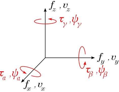
A rigid body permitted to move in 3 dimensions has 6 DoF. In a Cartesian coordinate system these correspond to translations inx,y, andzalong with their axial rotations, α, β, and γ, respectively. For mechanical systems translational DoFs are often represented in terms of force,f, and velocity, v, whilst rotational DoFs are described in terms of moment (or torque),τ, and angular velocity, ψ, as shown in Figure 2.1.2 For a rigid body the resultant velocity (or angular velocity) in any given DoF may be represented as a linear combination of all applied forces (and moments), weighted
2The conventional notation for angular velocity, ω, has been replaced with ψ so as to avoid
Chapter 2. Literature 12
by their appropriate mobilities. That is,
vi =
3
X
j=1
Yi,jfj+
6
X
k=4
Yi,kτk−3. (2.6)
The above may be expressed in a matrix notation as,
vx vy vz ψα ψβ ψγ =
Yxx Yxy Yxz Yxα Yxβ Yxγ Yyx Yyy Yyz Yyα Yyβ Yyγ Yzx Yzy Yzz Yzα Yzβ Yzγ Yαx Yαy Yαz Yαα Yαβ Yαγ Yβx Yβy Yβz Yβα Yββ Yβγ Yγx Yγy Yγz Yγα Yγβ Yγγ
fx fy fz τα τβ τγ (2.7)
the compact form of which is given in Equation 2.1, wherev= [vx, vy, vz, ψα, ψβ, ψγ]T is the resultant velocity vector, and f = [fx, fy, fz, τα, τβ, τγ]T is the applied force vector, each containing both translational and rotational DoFs.
f
z ,v
zf
y ,v
yf
x ,v
x,
ψ
β
τ
β
,
ψ
α
τ
α
,
ψ
γ
[image:34.596.211.445.388.569.2]τ
γ
Figure 2.1: Cartesian co-ordinate system and notation of forces and velocities.
Chapter 2. Literature 13
equation may be written in block form as,
v1 v2 ... vN =
Y11 Y12 . . . Y1N
Y21 Y22 . . . Y2N
... ... ... ... YN1 YN2 . . . YNN
f1 f2 ... fN (2.8)
where entries vN,fN and YNN are themselves block vectors and matrices.
At this point it is perhaps useful to make the distinction between positional and coordinate based DoFs. The former refers to the spatial position on a given struc-ture, whilst the latter refers to the coordinate in which a given variable is acting, i.e. translational or rotational. As such, each positional-DoF is made up of 6 coordinate-DoFs. In Equation 2.8 YNN may be considered the point mobility of the Nth positional-DoF, whilst its constituent elements, shown in Equation 2.7, correspond to coordinate-DoFs atN. The number of individual mobilities required to determine the state of a multi-DoF structure is consequently proportional to the square of the number of DoFs considered. For a linear time invariant (LTI) system the principle of reciprocity may be used to further reduce the number of measurements required [18]. The principle of reciprocity states that the input-output relation between any two DoFs remains unchanged if their force/response roles are interchanged, i.e. Yi,j = Yj,iT. As such, the number of individually required mobilities is only linearly proportional to the number of points. Under certain circumstances further reduc-tions may be made by considering geometric and coupling eects whilst neglecting non-contributing DoFs.
It is important to state that the work considered in this Thesis concerns only linear and time invariant systems, that is, those systems whose outputs may be regarded as weighted linear combinations of their inputs, and furthermore, those whose outputs do not depend upon the time at which the inputs are applied.
2.2 Source Characterisation
Chapter 2. Literature 14
desktop fan) is of interest. Key in the development of such prediction methodology is the successful characterisation of the contributing noise sources (for example; gearboxes, motors, compressors, etc.).
In the characterisation of an acoustic source (air-borne or structure-borne) the fun-damental aim may be stated as follows; to determine a physical set of quantities that describe both the active and passive behaviour of the source in such a way that they may later be used to predict an operational response in some other scenario. To aid the development of an appropriate method the International Organization for Standardization (ISO), Technical Committee on Acoustics TC43, Working Group outlined the following set of requirements that a suitable characterisation method should allow [24]:
1) Comparison of one source with another. 2) Comparison of sources with set limits. 3) Prediction of sound levels when installed.
4) Quantication of improvement in new low noise designs.
For many years the general consensus had been that the above were best achieved through a single valued frequency dependent quantity [25], for example sound power. However, as will be discussed shortly, such methods are generally unsuitable for the characterisation of structure-borne sources.
Depending upon the characterisation method employed, determined quantities may, or may not, be independent properties of the source. An independent quantity may be dened as one whose behaviour is an intrinsic property of the sub-structure under investigation, and therefore unaected by any modications made to its surround-ings. An independent characterisation is generally preferable in that it not only fulls above objectives, but satises the transferability requirements of dynamic sub-structuring (and therefore facilitates the construction of VAPs).
Chapter 2. Literature 15
An acoustic source may be considered either air-borne (or more generally uid-borne) or structure-borne depending upon the nature of the noise generating mechanisms, or the level at which the practitioner considers the problem. The characterisation of an air-borne source is more than often a simple procedure, owed in part to the weak coupling between the source and receiver sub-structures (i.e. the surrounding environment).3 As such, a number of well established sound power based
measure-ment procedures have been developed, standardised and subsequently adopted with industry [2628]. Unfortunately, procedures for the characterisation of structural sources are less well developed, not because they are of less signicance, but due to their greater complexity. The strong mechanical coupling between source and re-ceiver sub-structures results in the contamination of any directly measurable source quantity by the coupled receiver sub-structure. As such, the adoption of standard air-borne measurement procedures for structural source characterisation is inappro-priate. Consequently, the characterisation of structural sources has been a topic of great interest for many decades and a number of alternative methods have been proposed, including; the free velocity [29], operational force [30], blocked force [13], the source descriptor [31], the characteristic power, mirror power and maximum available power [32] and pseudo forces [33], to name but a few.
Further clarifying its requirement, Mondot and Peterson [31] proposed a potential independent source characterisation, the source descriptor and coupling function. It was shown that an expression for complex power between source and receiver sub-structures could be manipulated in such a way that yields two coecients; a source descriptor and a coupling function. The source descriptor is an independent source property that is proportional to power and involves both its active and pas-sive properties. The source descriptor may be interpreted as the source's ability to deliver power, whilst its product with the coupling function, a term proportional to the ratio of the source and receiver mobilities, determines the active power transmit-ted from the source to receiver. The original single contact point formulation was extended to multiple-contacts through the application of both `eective mobilities' [3436] and `interface mobilities' [37]. In the former, the resulting multi-point source descriptor became a function of force distribution and therefore dependent upon the receiver and no longer an independent property of the source. An independence re-taining generalization of the source descriptor to multi-point connected systems was later presented by Moorhouse [32] and termed the `characteristic power'. Dened as the dot product of the blocked force and free velocity vectors, the characteristic
Chapter 2. Literature 16
power provides an equivalent single point model for multi-point connected struc-tures. Unlike its single case counterpart, the determination of characteristic power requires the inversion of a measured source mobility matrix and is therefore suscep-tible to inversion error and ill-conditioning. Also presented by Moorhouse [32] were the concepts of mirror power and maximum available power, describing the power delivered by a vibrating source into a passive receiver structure whose properties are the mirror and complex conjugate of the source, respectively. With both the source descriptor and its generalization, the characteristic power, being dened on a power basis, translational and rotational contributions are dimensionally compatible and can therefore be collapsed into a single value. The characteristic power has since been introduced as part of the European standard EN 12354-5 for the prediction of structure-borne sound levels from building equipment [38].
Alternative power based methods, where the source is coupled to a standardized receiver structure have also been investigated, most notably the reception plate method [25, 39, 40]. Analogous to the reverberation method for the measurement of air-borne sound power, the reception plate method determines the power transmitted into a plate from the plate's loss factor, averaged velocity, mass per unit area, and surface area. Idealizations such as velocity and force sources hold for light (source mobility much less than plate mobility) and heavy structures, respectively. However, the characterisation is not independent and does not usually allow for the transfer of data, other than for approximate predictions in specic environments. Regardless of its limitations, the reception plate has been introduced as part of the European standard EN 15657-1 for the characterisation of structure-borne sound sources under laboratory conditions [41].
Chapter 2. Literature 17
between characterisation and installation may well pose problems. Furthermore, unlike power based methods, the dimensions of translational and rotational compo-nents are not compatible and therefore the free velocity can not be collapsed to a single frequency dependent variable. A practical application of the free velocity in the prediction of structure-borne noise emission from resiliently mounted machinery was demonstrated by Moorhouse and Gibbs [42, 43]. Assumptions based on the coupling and phase between contact DoFs allowed for a multi-contact theory to be established. Unfortunately the simplifying assumptions led to a reduction in appli-cability to a narrow range of cases. Recent work by Moorhouse et al. [44] has shown that the free velocity may be determined from in-situ operational measurements via the application of the round trip [45] and in-situ blocked force [13] relations. In doing so the free velocity may be determined from measurements conducted under representative mounting conditions, partly avoiding the need to freely suspend the source. Through a similar application of the round trip and in-situ blocked force relations it was also shown that the aforementioned characteristic power [32] may also be determined partly through in-situ operational measurements.
Perhaps the most common approach to source characterisation, particularly within the automotive and aerospace sector [30, 46] is the operational force method, also referred to as indirect force determination [47]. The operational force method deter-mines the forces acting on a receiver structure through an inverse approach whereby a measured receiver mobility matrix is inverted and subsequently multiplied by an operational velocity vector. Unfortunately, this does require the source and receiver sub-structures to be decoupled for the FRF measurement. In contrast to the direct measurement of free velocity, the operation force method does allow for operational measurements to be made in-situ, and thus avoids discrepancies between mounting conditions. Sadly, as with the characteristic power, the inverse approach is suscep-tible to ill conditioning. Fortunately, however, with the operational force method forming the basis of the well established diagnostic method `transfer path analysis` (TPA) [12], much work has been focused on the minimization of this error, with par-ticular emphasis on regularisation techniques, see [48, 49].4 Although well adopted
within industry and having become more or less standard practice, the operational forces obtained are not independent properties of the source and can not transferred between assemblies.
4An overview of the general concept of regularisation with regards to force identication may
Chapter 2. Literature 18
Janssens and Verheij proposed an alternative in-situ approach, referred to as the pseudo-force method, whereby the internal excitation of a source is reproduced by a set of ctitious forces on its outer surface [33]. Unlike the operational force method, pseudo forces may be determined using entirely in-situ measurements, thus allowing for diagnostic methods (similar to TPA) to be carried out without having to disman-tle the assembly. The pseudo force method has since been used to compare source strengths of dierent machines [50], and conduct diagnostic tests on ships [51, 52]. A similar method was presented by Ohlrich, instead termed the equivalent force method [53, 54]. Unfortunately, the forces determined using these methods have little physical meaning, and their transferability is limited. Furthermore, although they may produce equivalent response elds, it is dicult to directly compare the pseudo-forces of two dierent sources due to their dependence upon measurement position.
Chapter 2. Literature 19
based diagnostic procedure which, unlike the pseudo force methodology, pertains to quantities of physical meaning. It is perhaps of interest to note that pseudo forces, when determined at a source-receiver contact interface, are in fact identical to the blocked forces, unfortunately however, Jannsens and Verheij do not appear to have been aware of this at the time. The in-situ blocked force approach may additionally be considered a generalization of the single point synthesised force presented by Lai [66], and further realised as a consequence of an equivalent eld representation as shown by Bobrovnitskii [67].
As the eld currently stands, the in-situ blocked force method appears to oer the most suitable approach to independently characterising the activity of structural sources. To this end, the method is currently in the process of standardisation by the International Organisation for Standardisation, Technical Committee ISO TC43/ SC1/ WG57.
2.3 Dynamic Sub-structuring
Chapter 2. Literature 20
whether the work undertaken is of a theoretical or experimental nature. Outlined in Table 2.2 are the relative occurrences of domain types for theoretical and ex-perimental work. With the work of this Thesis concerned with the development of experimental methodologies, it is the FRF based formulations that are of particular interest here.
Physical State-space Modal FRF Theoretical Always Often Typical Unusual Experimental Never Unusual Typical Always
Table 2.2: Dynamic sub-structuring domains and their use in theoretical and experimental studies. Table adapted from [68].
Chapter 2. Literature 21
Generally speaking, a DSS approach may be considered a member of one of two families, depending on whether its formulation considers interface displacements or forces as unknowns. These are referred to as the primal and dual formulations, respectively [75].
Of the DSS methods available, the `classical impedance coupling' approach (also referred to as the basic impedance coupling process [76] or primal impedance for-mulation [75]) is arguably the most straightforward, both conceptually and in terms of its implementation. The method itself exists within the primal family and can be realised in a number of ways. It is well known that the enforcement of com-patibility and equilibrium between single DoF mechanical sub-structures results in a coupled structure whose impedance is equal to the sum of the individual sub-structure impedances. The extension of this concept to multi-DoF systems forms the basis of the classical impedance approach. Its implementation requires the free-interface mobility of each sub-structure to be measured and subsequently inverted. The resulting impedance matrices are then summed accordingly before being in-verted back to mobility form (usually required). It is this approach that is most often used in the assembly of nite element models. The classical approach requires all DoFs to be included in the inversion process, including those remote from the coupling interface. As such, ill-conditioning is a serious concern, particularly when dealing with large DoF assemblies.. Furthermore, matrix inversions are computa-tionally expensive procedures. The multiple inversions required at each frequency, along with the limited computational power and precision of early computers, meant that more computationally ecient algorithms were required.
Chapter 2. Literature 22
may it be expressed more simply, but only single coupling matrix is required to coupledN sub-structures, unlike Jetmundsen's approach which required N + 1.
2.3.1 Sub-structure Decoupling
In more recent years the DSS concept has been reversed, and instead used in the de-coupling of assemblies [7983]. Referred to here as dynamic sub-structure dede-coupling (DSSD), the procedure may be used to extract the independent passive property of a given sub-structure (i.e. the target sub-structure) from the measured properties of the coupled assembly and that of the remaining uncoupled sub-structure (i.e the residual sub-structure). Such a procedure oers the distinct advantage that the independent passive property of a given sub-structure may be determined without the need for free suspension, as would normally be required. This is of particular interest in cases where free suspension is simply not possible, for example; in cases where sub-structures are very large and heavy, and resilient mounting becomes im-practical (for example the decoupling of train carriages from their bogies [84]), or in cases where sub-structures are very small and lightweight, and resilient mounting does not suciently represent a free suspension.
Like DSS, the concept of DSSD is also of relevance to the eld of virtual acoustic prototyping. As previously stated, a fundamental requirement of a general VAP framework is that each sub-structure is characterised independently. This includes their passive properties. DSSD potentially oers an alternative means to characterise the passive properties of both source and receiver sub-structures.
2.4 Isolator Characterisation
The use of resilient elements, i.e. vibration isolators, for the abatement of structure-borne noise and vibration is wide spread throughout many engineering disciplines and their general application well understood. Notable examples include; auto-mobile engine mounts, resilient supports for buildings, resilient mounts/exible cou-plings for shipboard machinery and small isolators for domestic products.
Chapter 2. Literature 23
ratio. Dened for a single DoF system as the ratio of forces (or velocities) above and below the resilient element, the transmissibility oers an intuitive picture of the problem, providing a clear identication of the regions of amplication and at-tenuation [55]. Unfortunately, the transmissibility describes the performance of an assembly, not the resilient element itself. As such, it does not provide a transferable quantity, thus limiting its use to assemblies of similar dynamic behaviour. Alterna-tive approaches based on insertion loss [8587] and transmitted power [88, 89] have also been investigated yet, like the transmissibility, neither provide an independent characterisation of the resilient element. As with the characterisation of structural sources, a preferred quantity should be independent of the assembly in which the element is installed, and by virtue an intrinsic property of the resilient element. Such an independence ensures the transferability of data between assemblies and thus its compatibility with DSS procedures and, consequently, the general VAP framework outlined in Chapter 1.
The preferred quantity, for which the transmission of vibrational energy through a resilient element is described, is the dynamic transfer stiness [85]. The dynamic transfer stiness, denoted KIij (or reciprocally by KIji), is a frequency dependent
quantity that describes the relation between an applied displacement at one side of a mount to the resultant blocked force at the other,
¯f
i =Kijxj
i6=j. (2.9)
Determined by the elastic, inertial and damping properties of the element5, the
dynamic transfer stiness and can be related to other commonly used FRFs via Table 2.1. Much like a static measure of stiness, dynamic measures (i.e frequency dependent) often exhibit a sensitivity to static pre-load, dynamic excitation level, temperature and relative humidity [91]. The nature of these non-linearities make the complete characterisation of the resilient element a complicated and involved task. That said, accounting for the eects of temperature and relative humidity are merely experimental hurdles, albeit awkward ones to negotiate.
With each side of an element able to move in 6 coordinate DoFs, the dynamic transfer stiness is completely (neglecting any non-linearities) described by the6×6transfer
5At low frequencies only the elastic and damping properties contribute to the global behaviour