International Journal of Emerging Technology and Advanced Engineering
Website: www.ijetae.com (ISSN 2250-2459, ISO 9001:2008 Certified Journal, Volume 6, Issue 12, December 2016)
100
Optimization of Process Parameters of Activated Tungsten Inert
Gas welding for Ferrite Number of Duplex stainless steel Joints
G. Magudeeswaran
1, S. Suresh
2, L. Sundar
3 1Department of Mechanical Engineering, PSNA College of Engineering and Technology, Taminadu, India
2Departmetnt of Automobile Engineering, K.L.N College of Engineering and Technology, Taminadu, India 3
M/s Ador Welding Limited, Maharashtra Pune, India
Abstract— Duplex stainless steels (DSS) have a two-phase
microstructure of ferrite and austenite in approximately equal volume fractions, combining many of the beneficial properties of ferritic and austenitic steels. The weldability is good but proper welding procedures are needed to obtain sound welds. TIG welding process is one of the most popular technologies for welding thin materials in manufacturing industries because it produces high quality welds. The use of activated flux in TIG welding typically results in a 200–300% increase in penetration capability and can also be used for welding Duplex stainless steel (DSS) of higher thickness. The activated TIG welding (ATIG) process mainly focuses on increasing the depth of penetration and a greater attention is required for austenite – ferrite ratio after welding. The major influencing ATIG welding parameters that aid in controlling the austenite – ferrite ratio of DSS joints are electrode gap, travel speed, current and voltage. These parameters must be optimized to obtain greater penetration for DSS joints. Hence in this investigation an attempt has been made to optimize the above parameters of ATIG welding for austenite – ferrite ratio interms of ferrite number (FN) of ASTM / UNS S32205 DSS welds using Taguchi orthogonal array (OA) experimental design (DOE) and other statistical tools such as Analysis of Variance (ANOVA) and Pooled ANOVA techniques. The optimized welding parameters in this investigation is found to be 3 mm Electrode Gap, 100mm/min Travel speed, 160A Current, and 12V Voltage There is good agreement between the predicted and the experimental results.
Keywords—Duplex stainless steelATIG welding, Ferrite
Number
I. INTRODUCTION
Duplex stainless steel (DSS) with a dual phase structure of ferrite and austenite in approximately equal volume fractions combines many of the beneficial properties of both phases, for example, it shows good resistance to oxidation, corrosion, and stress corrosion associated with good mechanical properties and it is used critical applications likes oil and gas industries, heavy structural fabrication, marine engineering and defence applications etc. Welding is a predominant manufacturing process that is widely applied for fabrication in the above mentioned areas of applications.
The most important issue pertaining in welding of DSS is that the resultant microstructure after welding will exhibit unbalanced ferrite/austenite content in the weld metal region. This will affect the properties of the DSS joints and hence it will lead to poor performance. A major concern for duplex stainless steel is that welding can degrade the strength and corrosion resistance of the microstructures. Therefore, techniques that control the ferrite/austenite content of the weld metal are very important. Welding process, filler metal additions, shielding gas and heat input are important factors that contribute for inhibiting equal proportions of austenite-ferrite phase ratio (1:1) in the weld metal region and it is not practically possible in DSS joints and it is necessary to have 30-55 % ferrite content in all the zones of the joints. The entire issue of maintaining equal proportions of austenite – ferrite is based on several factors such as weld thermal cycle, filler metals, shielding gas etc [1-5].
International Journal of Emerging Technology and Advanced Engineering
Website: www.ijetae.com (ISSN 2250-2459, ISO 9001:2008 Certified Journal, Volume 6, Issue 12, December 2016)
101
However a greater attention is required for establishing better austenite – ferrite ratio in the various zones of the joints fabricated using ATIG welding process for joining DSS base meal [6-8].Hence, a systematic study is therefore required to obtain the desirable austenite – ferrite ratio for structural integrity of the DSS joints by properly controlling the weld thermal cycle of ATIG welding process. There is no logical experimental studies has been reported so far to analyze the influence of process parameters of ATIG welding process to obtain desirable ferrite ratio of DSS joints. Hence, in this study, an attempt has been made to optimize the above parameters of ATIG welding for austenite – ferrite content in terms of ferrite number (FN) of DSS joints using Taguchi orthogonal array (OA) experimental design and other statistical tools such as Analysis of Variance (ANOVA) and Pooled ANOVA techniques.II. WORK PLAN
The sequence of the work plan to optimize the process parameters for ATIG welding for 2205 DSS joints are detailed below:
A. Identifying the important process control parameters
B. Finding the levels of the process control parameters C. Selection of the experimental design matrix D. Conducting the experiments as per the design
matrix and recording of responses E. Evaluating the signal to noise (S/N) ratios F. Analysis of variance (ANOVA)
G. Selection of the optimum level of the factors & Checking the adequacy of the optimum process parameters through a confirmation test
A Identifying the important process control parameters
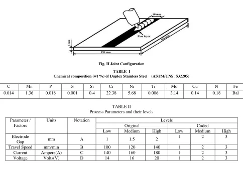
The base metal used in this investigation is a Duplex stainless steel (ASTM/UNS: S32205), the chemical composition of the same is presented in Table I. The microstructural feature of the base metal exhibits a dulplex structure with embedded grains of austenite (A) and ferrite (F) as shown in Fig 1
Fig.I Microstructure of the Base metal
The independently controllable predominant process parameters that control aspect ratio in ATIG welding were identified as: (i) Electrode gap, (ii) Travel speed, (iii) Current and (iv) Voltage .
B Finding the levels of the process control parameters
The range of the parameters were decided based on the several experimental trails and are illustrated in Table II.
C Selection of the experimental design matrix
Taguchi Design of Experiments L9 orthogonal array (OA) (Table III), was chosen as it was most suitable for the investigating four parameters each with three levels [9]. The signal – to –noise (S/N) ratio, which is a performance characteristic was calculated for each response and the mean S/N ratios at each level for various factors was determined. The optimal level, that is the largest S/N ratio among all the levels of the factors, was also determined. A statistical analysis of variance (ANOVA) was also performed to indicate which process parameters are statistically significant
D Conducting the experiments as per the design matrix
International Journal of Emerging Technology and Advanced Engineering
Website: www.ijetae.com (ISSN 2250-2459, ISO 9001:2008 Certified Journal, Volume 6, Issue 12, December 2016)
102
In this investigation, the autogenous welding was carried out using a typical branded activated flux : (Ador A –TIG Flux -1. The welding was carried out using a TIG welding machine ( Model: HF 3000 AD Make: Ador welding limited). The electrode gap and the travel speed was controlled and maintained by using an automatic torch traveler (Model: E –cutpro (Panther NM) Make: Ador welding limited). The welding was carried out by using 3.2mm non consumable Tungsten Electrode with High purity argon (99.99%) with a flow rate of 18 liters per minute. The welding was carried out in sequential order with the parameters as shown in Table III. The Ferrite content (FN:ferrite number) was measured in the weld zone for the joints fabricated by using ferritescope (Model: MP 30 E, Make: Fischer) to check the austenite –ferrite content and are tabulated in Table IV.EEvaluating the signal to noise (S/N) ratios
In this study, an L9 (34) OA with 4 columns and 9 rows
was used.
This array can handle three-level process parameters. Nine experiments were necessary to study the welding parameters using the L9 (3
4
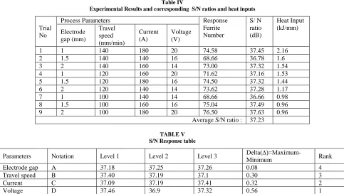
) OA. In order to evaluate the influence of each selected factor on the responses, the S/N ratios for each control factor has been calculated using the following equation as detailed in the literature [10-11]. Table IV shows the experimental results for Ferrite Number (FN) and the corresponding S/N ratios. Since the experimental design is orthogonal, it is then possible to separate out the effect of each parameter at the different levels [12]. In fact, average performance (mean S/ N ratio) of a factor at certain level is the influence of the factor at this level on the mean response of the experiments. The mean S/N ratio for each level of the parameters is summarized and the S/N response table for aspect ratio is shown in Table V. The rank 1 in the Table V indicated that voltage has more significant effect on the ferrite content followed by current, travel speed and electrodegap. .
[image:3.612.64.548.359.696.2]Fig. II Joint Configuration
TABLE I
Chemical composition (wt %) of Duplex Stainless Steel (ASTM/UNS: S32205)
TABLE II
Process Parameters and their levels Parameter /
Factors
Units Notation Levels
Original Coded
Low Medium High Low Medium High
Electrode
Gap mm A 1 1.5 2
1 2 3
Travel Speed mm/min B 100 120 140 1 2 3
Current Ampere(A) C 140 160 180 1 2 3
Voltage Volts(V) D 14 16 20 1 2 3
C Mn P S Si Cr Ni Ti Mo Cu N Fe
International Journal of Emerging Technology and Advanced Engineering
Website: www.ijetae.com (ISSN 2250-2459, ISO 9001:2008 Certified Journal, Volume 6, Issue 12, December 2016)
[image:4.612.64.547.332.605.2]103
TABLE IIIExperimental Layout using L9 (34) orthogonal array (OA) with coded and original level values
Trial No
Parameters / Factors
Electrode Gap [A] (mm) Travel Speed [B] (mm/min)
Current [C] Ampere(A)
Voltage [D] Volts (V)
Original Value
Coded Value
Original Value
Coded Value
Original Value
Coded Value
Original Value
Coded Value
1 1 1 140 3 180 3 20 3
2 1.5 2 140 3 140 1 16 2
3 2 3 140 3 160 2 14 1
4 1 1 120 2 160 2 20 3
5 1.5 2 120 2 180 3 16 2
6 2 3 120 2 140 1 14 1
7 1 1 100 1 140 1 14 1
8 1.5 2 100 1 160 2 16 2
9 2 3 100 1 180 3 20 3
Table IV
Experimental Results and corresponding S/N ratios and heat inputs
Trial No
Process Parameters Response
Ferrite Number
S/ N ratio (dB)
Heat Input (kJ/mm) Electrode
gap (mm)
Travel speed (mm/min)
Current (A)
Voltage (V)
1 1 140 180 20 74.58 37.45 2.16
2 1.5 140 140 16 68.66 36.78 1.6
3 2 140 160 14 73.00 37.32 1.54
4 1 120 160 20 71.62 37.16 1.53
5 1.5 120 180 16 74.50 37.32 1.44
6 2 120 140 14 73.62 37.28 1.17
7 1 100 140 14 68.66 36.66 0.98
8 1.5 100 160 16 75.04 37.49 0.96
9 2 100 180 20 76.50 37.63 0.96
Average S/N ratio : 37.23
TABLE V S/N Response table
Parameters Notation Level 1 Level 2 Level 3
Delta(∆)=Maximum-Minimum Rank
Electrode gap A 37.18 37.25 37.26 0.08 4
Travel speed B 37.40 37.19 37.1 0.30 3
Current C 37.09 37.19 37.41 0.32 2
International Journal of Emerging Technology and Advanced Engineering
Website: www.ijetae.com (ISSN 2250-2459, ISO 9001:2008 Certified Journal, Volume 6, Issue 12, December 2016)
[image:5.612.64.553.132.447.2]104
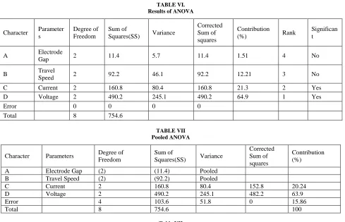
TABLE VI. Results of ANOVACharacter Parameter s
Degree of Freedom
Sum of
Squares(SS) Variance
Corrected Sum of squares
Contribution
(%) Rank
Significan t
A Electrode
Gap 2 11.4 5.7 11.4 1.51 4 No
B Travel
Speed 2 92.2 46.1 92.2 12.21 3 No
C Current 2 160.8 80.4 160.8 21.3 2 Yes
D Voltage 2 490.2 245.1 490.2 64.9 1 Yes
Error 0 0 0 0
Total 8 754.6
TABLE VII Pooled ANOVA
Character Parameters Degree of Freedom
Sum of
Squares(SS) Variance
Corrected Sum of squares
Contribution (%)
A Electrode Gap (2) (11.4) Pooled
B Travel Speed (2) (92.2) Pooled
C Current 2 160.8 80.4 152.8 20.24
D Voltage 2 490.2 245.1 482.2 63.9
Error 4 103.6 51.8 0 15.86
[image:5.612.79.538.467.601.2]Total 8 754.6 100
Table VII
Evaluation of the predicted Ferrite Number (FN) with the experimental results of the confirmation experiment using optimal condition
Parameters
A B C D
S/N Ratio Performance values of
Ferrite Number (FN) Electro
de Gap (mm)
Travel Speed (mm /min)
Current (A)
Voltage (V)
Prediction Experime
nt Prediction
Experime nt Optimum
Coded value
3 1 3 1 37.84 37.92 73.56 73.72
Optimum original value
3 100 160 12
F Analysis of variance (ANOVA)
The ANOVA is a common statistical technique to determine the percent contribution of each factor for results of the experiment [13]. It calculates parameters known as sum of squares (SS), corrected sum of squares (SS’), degree of freedom (D), variance (V), and percentage of the contribution of each factor (P) and the results of ANOVA are presented in Table VI.
International Journal of Emerging Technology and Advanced Engineering
Website: www.ijetae.com (ISSN 2250-2459, ISO 9001:2008 Certified Journal, Volume 6, Issue 12, December 2016)
105
The results of ANOVA after pooling for Ferrite Number (FN) are presented in Table VII. Pooled ANOVA values revealed that the voltage (63.9 %) and current (20.24 %) was significant factor for the ferrite number in the ATIG welding process.G Selection of the optimum level of the factors & Checking the adequacy of the optimum process parameters through a confirmation test
Once the optimal level of the design parameters is selected, the final step is to predict and verify the improvement of the quality characteristic using the optimal level of the design parameters. The predicted S/N ratio using the optimal level of the design parameters is calculated by equations as described in literature [14-15]. Table VIII shows the comparison of the predicted Ferrite Number (FN) with the experimental results using the optimal conditions. There is good agreement between the predicted and the experimental aspect ratio being observed. However, the optimized parameters obtained in this investigation for welding ASTM/UNS S32205 DSS should be justified for its use in real time engineering applications and are illustrated below
III. DISCUSSION
The maximum allowable heat input for 2205 DSS is 2.5 KJ/mm. However it is desirable to maintain a heat input of 0.75 to 1.5 KJ /mm [16]. The optimized welding parameters in this investigation is found to be 3 mm Electrode Gap, 100mm/min Travel speed, 160A Current, and 12V Voltage and the calculated heat input for the above parameters is found to be 1.152 KJ/mm is very much within the recommended levels. The desired ferrite content for 2205 DSS is 30-55% for better performance of the duplex stainless steel to serve the purpose for which it is intended and holds good for DSS welded joint too[17]. In this investigation the experimentally determined ferrite number in the weld region of the joints fabricated using the optimized process parameters is 73.72 and it is equivalent to 52.14 % of ferrite content. Hence the ferrite percentage (52.14,%) is well within the acceptable range. Hence, the optimized process parameters have been justified for welding 2205 grade DSS by ATIG welding process to achieve desirable austenite – ferrite content in the weld region. However the results obtained in this investigation is applicable only to 2205 grades of DSS for a plate thickness upto 6mm only. Moreover, the optimized parameters can only be used as an index for real engineering situations and is applicable only for ATIG welding process.
IV. CONCLUSION
In this Investigation, the Taguchi design method was used to optimise ATIG welding process parameters for ASTM/UNS S32205 DSS joints to obtain desirable autenite- Ferrite ratio interms of Ferrite Number (FN). Analysis of variance (ANOVA) and Pooled (ANOVA) techniques were used to examine the most significant factors. The following are the important conclusion derived.
I. The most significant parameters affecting the Ferrite Number are current and Voltage.
II. The optimized welding parameters in this investigation is found to be 3 mm Electrode Gap, 100mm/min Travel speed, 160A Current, and 12V Voltage
III. The ferrite content in the weld region and the heat input of the joints fabricated using the optimized process parameters is found to be well within the recommended level for 2205 DSS welds.
Acknowledgement
The authors are thankful to M/s Outokumpu Stainless Steel AB,Swden , Chennai for providing base material and M/s Ador Welding Limited, Mumbai for providing the fabrication facility for this investigation.
REFERENCES
[1] Muthupandi V, P. Bala Srinivasan, and S.K. Seshadri, 2003, Effect of Weld Metal Chemistry and Heat Input on the Structure and Properties of Duplex Stainless Steel Weld, Mater. Sci. Eng. A, (2003, 358) 9–16.
[2] Eriksson H and S. Bernhardsson, 1991, The Applicability of Duplex Stainless Steels in Sour Environments, Corrosion, (1991, 47 )719– 727
[3] Calliari, G. Straffelinii, and E. Ramous,2000, Investigation of Secondary Phase Effect on 2205 DSS Fracture Toughness, Mater. Sci. Technol.,(2010, 26), 81–86.
[4] Sherif E.M, Corrosion Behavior of Duplex Stainless Steel Alloy Cathodically Modified with Minor Ruthenium Additions in Concentrated Sulfuric Acid Solutions,2011, Int. J. Electrochem. Sci., (2011, 6), 2284–2298.
[5] Keshmiri H, Hot Deformation Characteristics of 2205 Duplex Stainless Steel Based on the Behavior of Constituent Phases,,2010, Mater. Des., (2010, 31), 220–226.
[6] Huang HY, Shyu SW, Tseng KH, Chou CP.2005 Evaluation of TIG flux welding on the characteristics of stainless steel., Sci Technol Weld Join (2005;10(5)), 566–73.
[7] Shyu SW, Huang HY, Tseng KH, Chou CP. 2008, Study of the performance of stainless steel A-TIG welds. J Mater Eng Perform (2008;17(2) ),197–201.
International Journal of Emerging Technology and Advanced Engineering
Website: www.ijetae.com (ISSN 2250-2459, ISO 9001:2008 Certified Journal, Volume 6, Issue 12, December 2016)
106
[9] Wang Y and D.O. Northwood, 2008,Optimization of the Polypyrrole-Coating Parameters for Proton Exchange Membrane Fuel Cell Bipolar Plates Using the Taguchi Method, J. Power Sour., (2008, 185) 226–232.
[10] Yousefieh M, M. Shamanian, and A. Saatchi, 2011, Optimization of the Pulsed Current Gas Tungsten Arc Welding (PCGTAW) Parameters for Corrosion Resistance of Super Duplex Stainless Steel (UNS S32760) Welds Using the Taguchi Method, J. Alloys Compd.,( 2011, 509), 782–788.
[11] BerilGonder Z,Y. Kaya, I.Vergili, andH.Barlas,2010, Optimization of Filtration Conditions for CIPWastewater Treatment by Nanofiltration Process Using Taguchi Approach, Sep. Purif. Technol.( 2010, 70) 265–273.
[12] Yang W.Hand Y.S. Tarng, 1998, Design Optimization of Cutting Parameters for Turning Operations Based on the Taguchi Method, J. Mater. Process. Technol., (1998, 84), 122–129.
[13] Yang k, E.C. Teo, and F.K. Fuss, 2007, Application of Taguchi Method in Optimization of Cervical Ring Cage, J. Biomech., (2007, 40), 3251– 3256.
[14] Yang W.Hand Y.S. Tarng,1998, Design Optimization of Cutting Parameters for Turning Operations Based on the Taguchi Method, J. Mater. Process. Technol., (1998, 84), 122–129.
[15] Kim KD, D.N. Han, and H.T. Kim, 2004,Optimization of Experimental Conditions Based on the Taguchi Robust Design for the Formation of Nano-Sized Silver Particles by Chemical Reduction Method, Chem. Eng. J., (2004, 104), 55–61.
[16] Outokumpu,How to weld Type 2205 code Plus Two Duplex Stainless steel, www.outokumpu.com/stainless/na