International Journal of Emerging Technology and Advanced Engineering
Website: www.ijetae.com (ISSN 2250-2459, ISO 9001:2008 Certified Journal, Volume 5, Issue 1, January 2015)
356
Fatigue Finite Element Analysis of Pressure Vessel for Vertical
Acceleration Loading
Kolate V. D.
1, Londhe B. C.
2, Bhane A. B.
31
PG student, 2Asst. Professor, SND COE & RC, Yeola, Maharashtra, India Abstract— The objective of analysis was to check fatigue
life of pressure vessel for vertical acceleration loading in accordance with ASME Section VIII, Div-2 Part 5 Ed. 2013. To find out stresses, finite element based modal and harmonic analysis is carried out. The study is conducted to determine the stress levels in the pressure vessel to a sufficient level of accuracy. The study is carried by using the following methodology. 3D model of pressure vessel is created by using CAD software. First 3D model is created including geometric details in corroded condition as per drawing. To achieve accuracy within satisfactory level, convergence study is conducting for +/- 3g vertical acceleration. Model is analyze for variety of element sizes and a size is chosen wherein satisfactory accuracy is obtained having less calculation time. The solution obtained is grid independent (results are not variable with respect to the size of mesh which correlates with real world scenario). This element size is used to mesh the remaining run for all the design cases. Model is analyzed with given data case of modal analysis and harmonic analysis for vertical acceleration loading. Fatigue calculations are perform based on the results of FEA analysis as per ASME Section VIII, Division 2, Part 5, for the above design cases. Results are studied and presented in the following sections.
Keywords— Vertical Acceleration, Fatigue Life, Stress, Modal Analysis, ASME Section VIII, Division 2, Part 5.
I. INTRODUCTION
A pressure vessel is defined as containers used for receiving or carrying, storing the fluid under pressure. When fluid remains stored in storage vessel it may undergo change in state and in case of steam boilers it combine with other reagent present in boiler. Pressure vessel has combination of high pressure together with high temperature and with flammable radioactive material because of hazards it is important to design the pressure vessel such that no leakage can take place as well as pressure vessel is to be designed carefully to withstand the high pressure and temperature without failure. For safety purpose pressure vessel should be designed according to ASME standards. In general the cylindrical shell is made of uniform thickness which is to be determined by the maximum circumferential stress due to the internal pressure. Modification is necessary to performed required function.
The life of a pressure vessel under vertical acceleration is related to the intensity of the stress and the number of cycles it is exposed to. The pressure vessel designed according to national and international code. The fatigue life curves used under ASME VIII-2 to calculate the permitted number of cycle life of a vessel are based on a large factor of safety compared with actual cycle life curves. We are using ASME section VIII- div.2. [1, 2]
The material used for pressure vessel are cast iron, Plain Carbon steel, Alloy steel, Aluminum alloys, copper and copper alloys, Nickel and Nickel alloys. Grey cast iron used for acid reaction vessel, acid coolers etc. Low carbon steels are used to construct light duty pressure vessel. Aluminum alloys are used for storage vessel for handling acids, peroxides, inorganic salts, sea water because it resist the attack by acid, peroxide etc. Copper and its alloy are used in food processing plants. Nickel and Nickel alloys used for handling the corrosive fluids. These alloys are very expensive.
II. SELECTION OF DESIGN PARAMETERS USED IN DESIGN OF PRESSURE VESSELS
There are three important parameter used for design of pressure vessel are internal pressure, allowable stress and corrosion allowance. There are three types of pressures which are related to pressure vessel that are maximum working pressure, design pressure and hydrostatic test pressure. The empirical relationship between maximum working pressure, design pressure and hydrostatic test pressure is given by,
1. Design Pressure, Pd = 1.05 times maximum working pressure.
2. Hydrostat test pressure = 1.365 times maximum working pressure.
International Journal of Emerging Technology and Advanced Engineering
Website: www.ijetae.com (ISSN 2250-2459, ISO 9001:2008 Certified Journal, Volume 5, Issue 1, January 2015)
357 It is necessary to avoid the corrosion and erosion of pressure vessel the corrosion allowance is to be considered for design of pressure vessel to increase thickness of pressure vessel. For cast iron, plain carbon steel the corrosion allowance is considered as 1.5 mm. if the thickness of cylindrical pressure vessel is greater than 30 mm then corrosion allowance is not necessary.
III. MECHANICAL DESIGN FOR PRESSURE VESSEL AS PER ASMESEC.VIII,DIV-1
Design data
Internal Operating pressure: - 3.5 Mpa. Design pressure: - 3.675 Mpa.
Design temp.:-75o C. Operating temp: - 65o C. Design No. of Cycles: - 1 * 108 Inside Diameter: - 1260 mm Pressure vessel length: - 1216 mm. Corrosion Allowance: - 3 mm
Type of Heads: - Semielliptical head with ratio of major axis to minor axis is 2.
[image:2.612.48.287.416.703.2]Type of support:- Saddle support.
TABLE I
MATERIALOF CONSTRUCTION OF PRESSURE VESSEL
Components Material Grade
Cylindrical Shell, Semielliptical
head SA 516 Gr. 70
Flanged joints, Nozzle and
openings SA 105
Saddle support SA 36
Cylindrical Shell Thickness, semielliptical Head Thickness and storage capacity of pressure vessel Calculation-
ts = + c
=
ts = 16.50 mm or 20 mm
or ts = 20 mm
The thickness of semi- elliptical head is given by
th = + c ..(1)
Where, Kf = 1/6 [2 + K12]
= stress intensification factor K1 = ratio of major axis to minor axis K1 = 2
The equation (1) becomes,
th = + c
= + 3
th = 17.376 mm or 20 mm. or th = 20 mm
inside corner radius is given by,
ric = 0.1 di ric = 0.1 126p ric = 126 mm
Straight flange length is given by,
Sf = 3 th Sf = 3 17.37 Sf = 50 mm
Storage Capacity of Pressure Vessel
Storage capacity of pressure vessel is given by,
V = [volume stored in vessel shell] + [volume stored in semielliptical head]
= [volume stored in vessel shell] + [volume stored in
straight flange of semielliptical heads] + [volume stored in semielliptical heads excluding
straight flange portion.
= di2 l + 2 [ di2 . Sf + Vh]
= di2 l + 2 [ di2 . Sf + Vh]
= 12602 1216 + 2 [ 12602 50 + 0.131 12603]
V = 2.293 m3
IV. FINITE ELEMENT ANALYSIS OF PRESSURE VESSEL
International Journal of Emerging Technology and Advanced Engineering
Website: www.ijetae.com (ISSN 2250-2459, ISO 9001:2008 Certified Journal, Volume 5, Issue 1, January 2015)
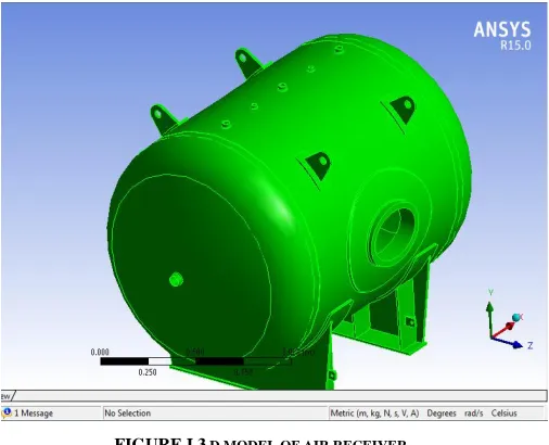
[image:3.612.48.301.186.391.2]358 The air receiver model is created by modeling software like SOLIDWORK , and it is imported in to the analysis software and boundary conditions are given to the imported model and result are evaluated by post processor.
FIGURE I 3 D MODEL OF AIR RECEIVER
[image:3.612.324.556.277.444.2]Figure I shows the imported geometry of air receiver. This geometry has been created in SOLIDWORK. Figure shows the 3D model of air pressure vessel with saddle support. Total volume and mass of the pressure vessel (air receiver) is 2.293 m3 and 1499.4 kg respectively.
FIGURE II MESHING OF PRESSURE VESSEL
Meshing is nothing but the discretization of object into the small parts called as the element. Figure II shows the meshed model of air receiver with solid 187 elements are used, this analysis having an element 162356 and node 321303.
Previous Studies show that the best results are obtained using solid 187 elementsmesh. Considering the concept of grid independence it is been found that this is the best suited size of mesh hence this size of mesh has been selected.
Modal Analysis- Modal analysis is performed as detailed below to determine 6 modes and their respective frequencies. Boundary Condition for Modal Analysis- The entire pressure vessel will be mounted through fixed saddle supports. The bottom surface of fixed saddle has fixed support boundary condition. Figure III shows Boundary Condition Plot for Modal Analysis
FIGURE III BOUNDARY CONDITION OF PRESSURE VESSEL FOR MODAL ANALYSIS
Result plot for Modal Analysis
TABLE III
MODE FREQUENCY TABLE PRESSURE VESSEL
Sr. No. Mode Frequency (Hz)
1 1 69.558
2 2 113.17
3 3 176.7
4 4 199.25
5 5 228.23
6 6 232.27
Total deformation for Modal Analysis
[image:3.612.48.300.464.642.2]International Journal of Emerging Technology and Advanced Engineering
Website: www.ijetae.com (ISSN 2250-2459, ISO 9001:2008 Certified Journal, Volume 5, Issue 1, January 2015)
[image:4.612.322.570.133.322.2]359 FIGURE IV TOTAL DEFORMATION PLOT OF PRESSURE VESSEL FOR
MODAL ANALYSIS
Results for Harmonic Analysis
Figure V shows vertical acceleration as boundary conditions of +/- 3g.
FIGURE V BOUNDARY CONDITION OF PRESSURE VESSEL FOR HARMONIC ANALYSIS
Equivalent Von Mises Stress Plot for Harmonic Analysis (for +/- 3g Vertical Acceleration) For +/- 3g acceleration loading the maximum stress response is calculated for 0.33 Hz (operating cycle frequency), maximum stress magnitude for the case is 10.922 Mpa as shown figure VI.
FIGURE VI VON MISSES STRESS PLOT OFPRESSURE VESSEL FOR HARMONIC ANALYSIS
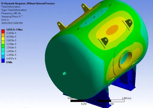
[image:4.612.51.295.137.307.2]Total Deformation Plot for Harmonic Analysis (for +/- 3g Vertical Acceleration) Maximum deformation for +/-3g acceleration, at 0.33 Hz has magnitude of 0.22132 mm as shown in figure VII.
[image:4.612.48.289.379.547.2] [image:4.612.324.580.406.587.2]International Journal of Emerging Technology and Advanced Engineering
Website: www.ijetae.com (ISSN 2250-2459, ISO 9001:2008 Certified Journal, Volume 5, Issue 1, January 2015)
360 V. FATIGUE LIFE CALCULATION FOR VERTICAL
ACCELERATION AS PER ASMESECTION VIII,DIV –2
Salt,k =
Where, ΔSP, k = 56.117 N/mm2
Kf = Fatigue Strength reduction factor = 1.2
Ke, k = Fatigue Penalty Factor = 1
=
Salt, k = 33.6702 N/mm2
As per Table 3.F.1 (ASME Section VIII, Division 2, Part 3) calculating the value of Sa for 1x10⁸ cycles, we can compare the value of Salt, k for present analysis. If the value of Salt, k is less than the corresponding value of Sa (at 1E8) we can conclude that the number of cycles for present case would be more than 1x10⁸. As per ASME stress required for 1x10⁸ is 70.5 Mpa and induced stress is less than that hence components is safe for more than 1x10⁸ cycles.
VI. CONCLUSION
Fatigue Finite element Analysis for vertical acceleration (+/- 3 g) is carried out for entire equipment for specified regeneration cycles. Fatigue life more than required number of cycle and therefore design is safe. Equivalent von misses stresses are within the range for harmonic analysis. Accordingly we conclude that all points for fatigue are within the allowable values specified by code.
REFERENCES
[1] Aditya M, etl. ―Finite Element Analysis of Horizontal Reactor Pressure Vessel Supported on Saddles‖ International Journal of Innovative Research in Science, Engineering and Technology ISSN: 2319-8753, Vol. 2, Issue 7, PP- 3213-3220, July 2013.
[2] Sagar P. Tiwatane, etl. ―Finite Element Analysis of Skirt to Dished junction in a Pressure Vessel‖, International Journal of Modern Engineering Research (IJMER), ISSN: 2249-6645, Vol. 3, Issue. 4, PP-2215-2218 Jul - Aug. 2013.
[3] Vikram V. Mane, etl., ―Finite Element Analysis of Ellipsoidal Head Pressure Vessel‖, International Journal of Engineering Research and Applications (IJERA) ISSN: 2248-9622 National Conference on Emerging Trends in Engineering & Technology (VNCET-30), PP.-132-138, Mar-2012.
[4] Bandarupalli Praneeth, etl. ―Finite Element Analysis of Pressure Vessel and Piping Design‖, International Journal of Engineering Trends and Technology, ISSN: 2231-5381, Volume3, Issue5, PP-567-570, 2012.
[5] Christopher Corneliu Manu, ―Finite Element Analysis of Stress Rupture in Pressure Vessels Exposed to Accidental Fire Loading‖, Queen’s University Kingston, Ontario, Canada July- 2008. [6] L. P. Zick, ―Stresses in Large Horizontal Cylindrical Pressure
Vessels on Two Saddle Supports‖, the Welding Journal Research Supplement, PP- 959-970, September 1951.A. Saffar, A. Shojaei. 2012. Effect of rubber component on the performance of brake friction materials.
[7] V.B. Bhandari ―Design of machine elements‖ Text book, third edition.
[8] R.S Khurmi, etl. ―Design of machine elements‖ Text book, third edition.