International Journal of Emerging Technology and Advanced Engineering
Website: www.ijetae.com (ISSN 2250-2459, ISO 9001:2008 Certified Journal, Volume 3, Issue 9, September 2013)
110
Dynamic Analysis of Reinforced Concrete Building with Plan
Irregularities
Mohammed yousuf
1, P.M. shimpale
2 1M.E. structure- student, 2Associate Professor, Department of Civil Engineering, M.G.MS’ college of Engineering Nanded
Abstract— The main objective of earthquake engineering is
to design and build a structure in such a way that the damage to the structure and its structural component during an earthquake is minimized. This paper aims towards the dynamic analysis of reinforced concrete building with plan irregularity. Four models of G+5 building with one symmetric plan and remaining irregular plan have been taken for the investigation. The analysis of R.C.C. building is carried out with the FE based software ETABS 9.5. Estimation of response such as; lateral forces, base shear, storey drift, storey shear is carried out. Four cross sectional variation in columns section are considered for studying effectiveness in resisting lateral forces. The paper also deals with the effect of the variation of the building plan on the structural response building. Dynamic responses under prominent earthquake, related to IS 1893–2002(part1) have been carried out. In dynamic analysis; Response Spectrum method is used. The CQC (complete quadratic combination) method has also been employed for each model for estimation of dynamic response for 5%, 10%, 15%, and 20% damping and dynamic responses
were compared.
Keywords— Earthquake Analysis, Response Spectrum
Analysis, CQC Method, plan irregularity, dynamic
comparisons.
I. INTRODUCTION
Structural design of buildings for seismic loading is primarily relate with structural safety against major earthquakes, but serviceability and the potential for economic loss are also of concern. Seismic loading requires an understanding of the structural behavior under large inelastic deformations. Behavior under this loading is fundamentally different from wind or gravity loading, requiring much more detailed analysis to assure acceptable seismic performance beyond the elastic range. Some structural damage can be expected when the building experiences design ground motions because almost all building codes allow inelastic energy dissipation in structural systems.[1] The first step in dynamic analysis is to develop a mathematical model of the building, through which estimates of strength, stiffness, mass, and inelastic member properties (if applicable) are assigned. In general, for a multistory building it is necessary to take into account contributions from more than one mode.
Each mode has its own particular pattern of deformation. The contribution of higher modes diminishes very quickly, and it is nearly always sufficient to consider the first three modes of vibration to obtain reasonably accurate results for most short- to medium-rise buildings. For high-rise buildings, it may be necessary to consider more than three modes. The significant modes that contribute to response may be determined by selecting the number of modes such that their combined participating mass is at least 90% of the total effective mass in the structure. [2]
Objectives
The main objectives of present study include:
1.The effect of irregular plan on structural response
under seismic loading.
2.Dynamic analysis of framed structures using Response
Spectrum Method by CQC method for 5%, 10%, 15%, and 20% damping
3.Comparative dynamic analysis of irregular building by
using ETAB software has been investigated.
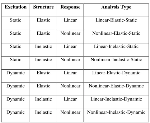
Basic types of structural analysis
There are basically eight types of analysis in the field of
[image:1.612.313.554.516.713.2]structural analysis and they are shown in TABLE I.
Table I
Basic Types of Structural Analysis
Excitation Structure Response Analysis Type
Static Elastic Linear Linear-Elastic-Static
Static Elastic Nonlinear Nonlinear-Elastic-Static
Static Inelastic Linear Linear-Inelastic-Static
Static Inelastic Nonlinear Nonlinear-Inelastic-Static
Dynamic Elastic Linear Linear-Elastic-Dynamic
Dynamic Elastic Nonlinear Nonlinear-Elastic-Dynamic
Dynamic Inelastic Linear Linear-Inelastic-Dynamic
International Journal of Emerging Technology and Advanced Engineering
Website: www.ijetae.com (ISSN 2250-2459, ISO 9001:2008 Certified Journal, Volume 3, Issue 9, September 2013)
111
II. METHODS OF DYNAMIC ANALYSIS
Methods of Dynamic Analysis
The methods of dynamic analysis used here are Time History Method and Response Spectrum Method.
Time History Method
Time-history analysis is a step-by-step analysis of the dynamical response of a structure to a specified loading that may vary with time. The analysis may be linear or non linear. Time history analysis is used to determine the dynamic response of a structure to arbitrary loading. [3]
Response Spectrum Method
The Response Spectrum is a method of estimation of
maximum responses (acceleration, velocity and
displacement) of a family of SDOF systems subjected to a prescribed ground motion. The RSM utilizes the response spectra to give the structural designer a set of possible forces and deformations a real structure would experience under earthquake loads.
In IS:1893, two methods, one Seismic Coefficient and other Response Spectrum method is described to carry out the analysis for Earthquake forces. One Table (in Clause 4.2.1) is also provided to decide upon the method to be used, depending upon Building Ht. and Zone. At the bottom of this table, it is clearly mentioned that building with irregular shape and/or irregular distribution of mass and stiffness in horizontal and/or vertical plane, shall be analyzed as per Response Spectrum Method. For all practical reasons, no building is uniform in all the respects (i.e. shape, mass/stiffness distribution in horizontal and vertical plane). This means that for no building, the Seismic Co-efficient method shall be resorted. Response Spectrum method, being time consuming and tedious process, most of time, it resort to computer applications. Now while, modeling the structure, in most of available software’s, usually, we model the space frame, neglecting the in-fill wall stiffness. These results in flexible frames, and due to which, in most of Cases, the program gives a higher Time Period and results into lower base shear. Today with the availability of Powerful Computers and Software, the seismic coefficient method should not be applied to anything other than mass concrete!! In such a case a reduction coefficient would not be applicable. The infill walls and slabs should be modeled. If software has plate modeling capability, these can be modeled as plates. Otherwise an "equivalent” pair of diagonal members connecting the four corners of the slab or wall (in each bay) would simulate the shear behavior.
The diagonal members shall be 'truss' members - i.e. capable of only carrying axial load. The elastic properties can be derived from first principle, by matching forces and deformations in a plate and the equivalent diagonals. [4]
General: This section provides required minimum standards for the equivalent lateral force procedure of seismic analysis of structures. For purposes of analysis, the
structure is considered to be fixed at the base. For
limitations on the use of this procedure.
Seismic Base Shear:The seismic base shear VB in a given
direction shall be determined in accordance with the following equation:
Where:
VB= Ah W
Ah = the seismic response coefficient
W = the total dead load and applicable portions of other loads:
Calculation of Seismic Response Coefficient: The seismic
response coefficient Ahshall be determined in accordance
with the following equation:
Rg
ZI
S
A
ah
2
Where:
Z =Zone factor given in
Sa/g = average response acceleration coefficient
R = the response reduction factor
I = the importance factor depending upon the functional use of structure
Period Determination: The fundamental period of the
building, T, in the direction under consideration shall be
established using the structural properties and
deformational characteristics of the resisting elementsin a
properly substantiated analysis or, alternatively, it is permitted to be taken as the approximate fundamental
period, T, determined in accordance with the requirements
of Sec. The fundamental period, T, shall not exceed the
product of the coefficient for upper limit on calculated
periodfrom and the approximate fundamental period T.
T=0.075h ¾ for R.C.frame building
T=0.085h ¾ for Steel frame building Where
International Journal of Emerging Technology and Advanced Engineering
Website: www.ijetae.com (ISSN 2250-2459, ISO 9001:2008 Certified Journal, Volume 3, Issue 9, September 2013)
112
Vertical Distribution of Seismic Forces: The lateral force,
F (kip or KN), induced at any level shall be determined
from the following equations:
n j i j i i B i h W h W V Q 1 2 2 Where
Q
i= Design lateral force at floor i
Wi
Seismic Weight of floor i
h
i
Height of floor i measured from base
n
Number of storey’s in the building is the number oflevels at which the masses are located
Complete quadratic combination (CQC):The Complete quadratic combination (CQC) rule for modal combination is applicable to a wider class of structures as it overcomes the limitations of the SRSS rule. The method is based on random vibration theory. It has been incorporated in several commercial analysis programs. A double summation is used to estimate maximum responses,
r i r j j ij i 1 1
In which,
ij is a cross-modal coefficient (alwayspositive), which for constant damping is evaluated by
r= number of modes being considered
i=response quantity in mode i
j= response quantity in mode j
2
2 2
25 . 1 2
1
4
1
1
8
ij
=modal damping ratio
=frequency ratio= i j
j=circular frequency in jth mode
i= circular frequency in ith modeSimilar equations can be applied for the computation of member forces, interstorey deformations, base shears and overturning moments.
III. STRUCTURAL MODELLING AND ANALYSIS
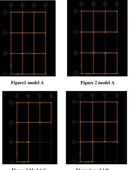
Four building of G+5 stories regular and irregular in plan are modeled as of fixed base building and analyzed with soft computing tool E-TABS V 9.5. Dynamic responses of building are studied. Regular model consists of symmetry in plan as well as elevation and irregular
modelconsists of plan asymmetry but elevation symmetric.
[image:3.612.331.556.400.696.2]The CQC method is employed to get dynamic responses for 5%, 10%, 15%, 20% damping for all four models.
Figure 1 shows the plan of base model and figure 2, 3, 4 shows the developed irregular plans from base model. Each model has plot dimensions 12× 18 m in x-direction and y-direction respectively. The developed models are C-shape, L-shape and irregular in plan as shown in figure 1, 2, 3, and 4.
For the analysis of fixed base building response spectrum method as per I.S. 1893: 2002 is used. The graph represents response spectra for 5%, 10%, 15% and 20% damping rocky soil (shown in Figure 5). X-axis shows period “T” in seconds and Y-axis shows spectral
acceleration coefficient(sa/g).
Figure1 model A Figure 2 model A
International Journal of Emerging Technology and Advanced Engineering
Website: www.ijetae.com (ISSN 2250-2459, ISO 9001:2008 Certified Journal, Volume 3, Issue 9, September 2013)
[image:4.612.321.568.125.293.2]113 Figure 5 Response Spectra for 5%, 10%, 15%, 20% damping
For the dynamic analysis of building the assumed preliminary data as follows
Type of structure =Multi-storey rigid jointed plane frame, seismic zone = IV , zone factor=0.24,number of storey's=G+5.storey height=3.5, base floor height=2,infill
wall=230mmthick,imposed load=5 KN/m2, Materials=
Concrete (M25) and Reinforcement Fe415, Depth of
slab=150 mm, Specific weight of RCC=25 KN/m3, ,
Specific weight of infill=20 KN/m3, Importance
factor=1.The various sizes of columns and beams shown below
C1=230 mm x 380 mm Outer column
C1=230 mm x 800 mm Interior column up to G+1 C1=230 mm x 600 mm Interior column up to G+3
C1=230 mm x 450 mm Interior column up to G+5
BM=230mm x 600 mm Beam in Longitudinal direction
BO=230mm x 600 mm Beam in Transverse direction
IV. RESULT AND DISCUSSIONS
Base Shear:
Base shear is calculated by using IS 1893-2002 method for all four model s in Figure 6 illustrate the comparison of base shear using lateral load Equivalent method. The lower base shear is getting in model C and the higher base shear is getting in model A.
Figure 6 Base shear
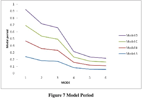
[image:4.612.62.281.126.307.2]Modal Natural Period (Tk): - The modal natural period k is the time period of vibration in mode k. The modal natural period k is more in model A as compared to model B and model C. The modal natural period k is somewhat is less in model D as compared to model A. Therefore the Sa/g value is more in model A as compared to remaining model as shown in Figure 7.
Figure 7 Model Period
[image:4.612.323.565.394.561.2]International Journal of Emerging Technology and Advanced Engineering
Website: www.ijetae.com (ISSN 2250-2459, ISO 9001:2008 Certified Journal, Volume 3, Issue 9, September 2013)
[image:5.612.50.288.125.490.2]114 Figure 8 Response Spectrum Acceleration For 5% Damping After
[image:5.612.329.558.133.317.2]Analysis
Figure 9 Response Spectrum Acceleration For 10% Damping After Analysis
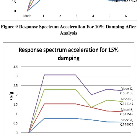
[image:5.612.323.565.438.600.2]Figure 10 Response Spectrum Acceleration For 15% Damping After Analysis
Figure 11 Response Spectrum Acceleration For 15% Damping After Analysis
Natural Frequency: Natural frequency is the reciprocal of model natural period. The dynamic responses are vary according to different natural frequency because the number of modes to be considered is depend upon the natural frequency. If the natural frequency beyond 33Hz those modes are to be considered and model combination will be carried out only for modes up to 33Hz according to IS -1863-2002. The natural frequency for various modes as shown in Figure 12.
Figure 12 Natural Frequency
[image:5.612.52.284.444.674.2]International Journal of Emerging Technology and Advanced Engineering
Website: www.ijetae.com (ISSN 2250-2459, ISO 9001:2008 Certified Journal, Volume 3, Issue 9, September 2013)
115 Figure13 Storey Drift for Model A
Figure 14 Storey Drift for Model B
[image:6.612.319.564.124.316.2]Figure 15 Storey Drift for Model C
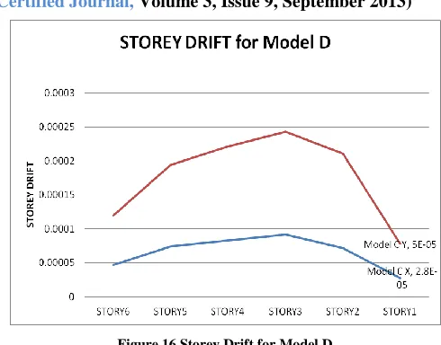
Figure 16 Storey Drift for Model D
Storey Shear by CQC Method:
The storey shear reduces linearly for each in increase in damping percentage. Therefore we have to consider what amount of percentage of damping is required for the building in respective zones because in severe zone more damping is required to reduce structural damages and to get maximum response of structure against damages. But generally 5% damping is considered as critical damping for earth quake design of structure. But for 10% damping we are getting optimum value for spectra x and spectra y. the storey shear by CQC method after analysis that are getting as shown in TABLEII and TABLE III below.
TABLEI
STOREY SHEAR BY CQC METHOD (SPECTRA X)
Storey Shear by CQC method (spectra x)
Model A/L
Ratio
Storey Shear 5%
Storey Shear 10%
Storey Shear 15%
Storey Shear 20%
[image:6.612.321.572.496.603.2]International Journal of Emerging Technology and Advanced Engineering
Website: www.ijetae.com (ISSN 2250-2459, ISO 9001:2008 Certified Journal, Volume 3, Issue 9, September 2013)
116 TABLEIII
STOREY SHEAR BY CQC METHOD (SPECTRA Y)
Storey Shear by CQC method (spectra Y)
Model A/L
Ratio
Storey Shear 5%
Storey Shear 10%
Storey Shear 15%
Storey Shear
20%
A 0 1200 960 843 726
B 0.33 1010 813 714 615
C 0.66 741 594 522 449
D 0.33 969 777 682 587
V. CONCLUSION
From the dynamic analysis of G+5 RCC frames with plan irregularity we have got the following conclusions.
1)Dynamic analysis of buildings requires careful
structural modeling, understanding appropriate
selection of ground motion records, and thorough knowledge and familiarity of the analyst with the procedures and computer software employed.
2)Seismic design of structures is typically based on the
modal analysis with response spectrum that is generally considered a conservative approach.
3)Base shear is calculated by using IS 1893-2002
method for all four model s in Figure 6.27 illustrate the comparison of base shear using lateral load Equivalent method. The lower base shear is getting in model C and the higher base shear is getting in model A.
4)For higher and unsymmetrical buildings Response
Spectrum Method should be used for symmetric building we can use lateral load equivalent method to the best way. But for unsymmetrical building requires more accurate analysis therefore Response Spectrum Method should be used.
5)Irregularity in plan can result in complex dynamics
and irregular response as the above discussion in performance analysis the irregular responses we are getting for models.
6)Where Plan irregularities exist, check the lateral-force
resisting elements using a dynamic analysis so that more realistic lateral load distribution can be achieved because irregularity in plan can result in irregular response so to resist the lateral loads it is necessary to check lateral- force resisting elements.
7)The Complete quadratic combination (CQC) rule for
modal combination is applicable to a wider class of structures as it overcomes the limitations of the other rule because the method is based on random vibration theory.
REFERENCES
[1] Romy Mohan C Prabha(2011): Dynamic Analysis of RCC Buildings with Shear Wall .
[2] P. P. Thakare O. R. Jaiswal(2011): Comparative Study of Fixed Base and Base Isolated Building using Seismic Analysis
[3] Chopra A. K, Dynamics of structures theory and applications to earthquake engineering, Prentice- Hall, Englewood Cliffs, N.J. 1995. [4] IS: 1893 (Part 1) 2002- Indian standard- “Criteria for earthquake
resistant design of structures”, Bureau of Indian Standards, New Delhi.