International Journal of Emerging Technology and Advanced Engineering
Website: www.ijetae.com (ISSN 2250-2459,ISO 9001:2008 Certified Journal, Volume 5, Issue 3, March 2015)
601
The Speed Control of a 3-phase Induction Motor Using PI
(Proportional Integral) Control Method and Fuzzy Logic
Control Method
C S Kailash
1, Melvin george
2, Sreekanth M
3,
Gomathy S
4 1,2,3Student, Dept. of EEE, ADI Shankara Institute of Engg & Tech, Kalady, India,
4Asst. Professor, Dept. of EEE, ADI Shankara Institute of Engg & Tech, Kalady, India,
Abstract - In this paper, we discuss the speed control of a 3-phase induction motor using PI (Proportional Integral) control method and fuzzy logic control method. The induction motor was designed using indirect vector control. We simulated our induction motor model using MATLAB/SIMULINK. We obtained the speed control results using PI controller. Next simulated our induction motor model using fuzzy logic controller. The result obtained was compared with that of PI.
Keywords - Fuzzy logic, Induction motor, scalar control, simulink, speed control, Proportional Integral, Fuzzy logic controller, indirect vector control.
I. INTRODUCTION
Induction motor is the most common electrical machine used in modern industries. It has gained such popularity due to its various advantages. The various advantages are high efficiency, low cost, good self-starting [1], simplicity in design, the absence of the collector brooms system, and a small inertia. Even though it has a wide range of advantages it has quite a few disadvantages. Induction motor has disadvantages, such as complex, multivariable and nonlinear of mathematical model of induction motor, and the induction motor is not inherently capable of providing variable speed operation.
The interest in sensor less drives of induction motor (IM) has grown significantly over the past few years due to some of their advantages, like mechanical robustness, less maintenance, and basic(easy) construction. These applications includes paper and textile mills, pumps and fans, electric and hybrid vehicles subway and locomotive propulsions, , machine tools and robotics, home appliances, air conditioners and heat pumps, rolling mills, wind generation systems. Therefore, Induction motors have been used more in the industrial variable speed drive system with the development of the vector control technology.
Therefore the electrical drives good dynamic performance is mandatory so as to respond the changes in command speed and torques. The most commonly used controller for the speed control of Induction motor is Proportional plus Integral (PI) controller.
However, the PI controller has some demerits such as: sensitivity to controller gains, the high starting overshoot and sluggish response due to sudden disturbance. Therefore to overcome these problems, replacement of PI controller by an intelligent controller based on Fuzzy set theory [5] is proposed in this work. The fuzzy logic controller has certain advantages compared to the classical controllers such as low cost, simplicity of control, and the possibility to design without knowing the exact mathematical model.
The vector control methods are normally classified into two types, direct vector control and indirect vector control methods. In this paper the Indirect Vector Control method is used. Because of it’s, fast dynamic response and speed response without cogging or torque pulsations at low speed, smooth speed reversal under any torque conditions.
A new control of a drive system is formulated and it is often convenient to study the system performance by using Matlab/Simulink package, when compared to other packages like EMTP and PSPICE. The simulation using Matlab has an ease in modeling, the transients of electrical machines and drives and to include controls in the simulation [3]. Then the superior control performance of the proposed controllers is demonstrated at Simulink platform using the Fuzzy logic tool box for different operating conditions.
II. CONTROLLING SCHEMES FOR SPEED CONTROL OF THREE PHASE INDUCTION MOTOR
A. Scalar Control
International Journal of Emerging Technology and Advanced Engineering
Website: www.ijetae.com (ISSN 2250-2459,ISO 9001:2008 Certified Journal, Volume 5, Issue 3, March 2015)
602
If torque is increased by incrementing the slip then the flux tends to decrease [2]. It has been noted that the flux variation is also sluggish. Decreases in flux then compensated by the sluggish flux control loop feeding an additional voltage.B. Vector Control or Field Oriented Control (FOC):
In DC machine the field flux is perpendicular to the armature flux. These two fluxes produce no net interaction on one another, because they are orthogonal. Adjusting the field current can be used for controlling the DC machine flux, and thus torque can also be controlled independently of flux by adjusting the armature current. An AC machine is not simple because of the interactions between the stator and the rotor fields. Due to this the orientations are not held at 90 degrees but it varies with the operating conditions. To obtain DC machine-like performance in holding a fixed and orthogonal orientation between the field and armature in an AC machine can be obtained by orienting the stator current with respect to the rotor flux so as to attain independently controlled flux and torque. This control scheme is called flux-oriented control or vector control. Vector control is applicable to both synchronous and induction motors.
C. Proportional – Integral (PI) Control
In this project complete mathematical model of induction motor is described and simulated in MATALAB. The performance of vector control drive with proportional plus integral (PI) controller is analyzed. Control law used for this strategy is given by
T = Kp e + Ki ∫e dt
Its output is the updating in PI controller gains (Kp and Ki) based on a set of rules to maintain excellent control performance even in the presence of drive nonlinearity and parameter variation. The use of PI controllers for speed control of induction machine drives is characterized by an overshoot during tracking mode and a poor load disturbance rejection [2]. This is mainly due to the fact that the complexity of the system does not allow the gains of the PI controller to exceed a certain low value and at the starting mode the high value of the error is amplified across the PI controller causing
annoyance high variations in the command torque.
Whenever the gains of the controller exceed a certain value, the variations in the command torque become too high and will destabilize the system. In order to overcome this problem we propose the use of a limiter ahead of the PI controller [2]. This limiter causes the speed error to be maintained within the saturation limits provoking, when appropriately chosen, smooth variations in the command torque even when the PI controller gains are very high[2].
The motor reaches the reference speed rapidly and without overshoot, when step commands are tracked with almost zero steady state error and no overshoot. When load disturbances are rapidly rejected and variations of some of the motor parameters are fairly well dealt with.
D. Fuzzy Logic Control
Due to continuously developing automation systems and more demanding small Control performance requirements, conventional control methods are not always adequate. In another word, practical control problems are usually imprecise. The input output relations of the system may be uncertain and they can be changed by unknown external disturbances. Thus a more efficient control scheme called fuzzy logic was implemented. Fuzzy control is based on fuzzy logic [4]. Which provides an efficient method to handle in exact information as basis reasoning. With the help of fuzzy logic it is possible to convert knowledge, which is expressed in an uncertain form, to an exact algorithm. Fuzzy logic embodies human-like thinking into a control system. A fuzzy controller employs a mode of approximate reasoning resembling the decision making route of humans (i.e. The process people use to infer conclusions from what they know) [2]. Fuzzy control has been primarily applied to the control of processes through fuzzy linguistic descriptions stipulated by membership functions.
III. INDIRECT VECTOR CONTROL INDUCTION MOTOR
DRIVE -MATHEMATICAL MODEL:
A. Hysteresis Current Regulator:
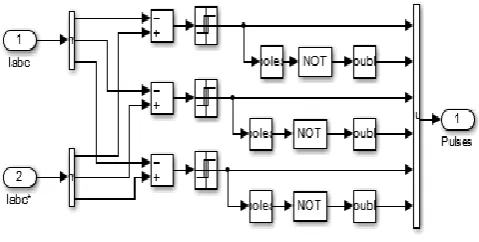
[image:2.595.318.558.587.708.2]The current regulator, which consists of three hysteresis controllers, is built with Simulink blocks [2]. The motor actual currents are cater by the measurement output of the Asynchronous Machine block. The actual motor currents and reference current are compared in hysteresis type relay.
International Journal of Emerging Technology and Advanced Engineering
Website: www.ijetae.com (ISSN 2250-2459,ISO 9001:2008 Certified Journal, Volume 5, Issue 3, March 2015)
603
B. Flux Calculation Block
Fig 2: Flux Calculation block diagram
Lr = Ll'r +Lm = 0.8 +34.7= 35.5 mH
Lm = 34.7 mH
Tr = Lr / Rr = 0.1557 sec
Rr = 0.228 Ω
Phir = Lm *Id / (1 +Tr .s)
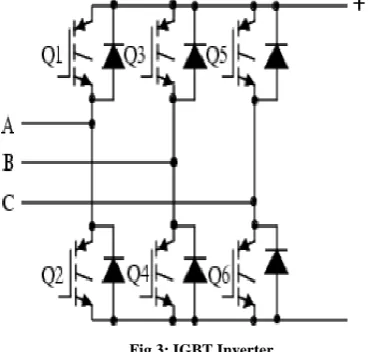
C. Universal Bridge (IGBT) Inverter:
The Universal Bridge block implements a universal three-phase power converter that consists of up to six power switches connected in a bridge configuration. The type of power switch and converter configuration is selectable from the dialog box. Power Electronic device and Port configuration options are selected as IGBT/Diode and ABC as output terminals respectively. The DC link input voltage is represented by a 780 V DC voltage source [2].
Fig 3: IGBT Inverter
D. Theta Calculation Block:
The rotor flux position (θe) is calculated.
Fig 4: θe Calculation block diagram
Teta=Electrical angle=integral(wr+wm)
wr=Rotor frequency in rad/s=Lm*Iq / (Tr*Phir)
wm=Rotor mechanical speed in rad/s
Lm= 34.7mH
Lr=LI’+Lm=0.8+34.7=35.5mH
Rr=0.228 ohms
Tr= Lr/Rr= 0.1557 s
[image:3.595.63.254.449.625.2]E. d-q to abc Transformation Blocks
Fig 5: d-q to abc transformation block diagram
F. abc to d-q Transformation Blocks
International Journal of Emerging Technology and Advanced Engineering
Website: www.ijetae.com (ISSN 2250-2459,ISO 9001:2008 Certified Journal, Volume 5, Issue 3, March 2015)
604
IV. ALGORITHM OF INDIRECT VECTOR CONTROL1. The induction motor is fed by a variable frequency, variable voltage PWM inverter [1], which operates in current control mode [1]. The motor speed ω is examined with the reference speed ω* and the error is produced which is fed to the speed controller. The output of speed controller is electromagnetic torque Te*.
2. The quadrature-axis stator current reference iqs* is calculated from electromagnetic torque reference Te* as
qs* ( ) ( ) ( r
m) e* r
Where ̂r =|ψr|est is the estimated value of rotor flux linkage given by ,
̂r
m ds r
Where, τr = is the rotor time constant.
3. The direct-axis stator current reference ids* is obtained from reference rotor flux input |ψr|*.
ds*
| r*|
m
4. The rotor flux position e required for coordinates transformation is obtained from the rotor speed r and slip frequency sl. e is calculated as
e ∫ e ∫ r s r s
5. The slip frequency is calculated from the stator reference current iqs* and the motor parameters. is given by from equation [1],
sl
m r
r r qs
6. The iqs* and ids* current references are converted into phase current references ia*, ib*, ic* using inverse park transform (two phase to three phase conversion) & fed to the current controller [1]. The controller processes the measured and reference currents to produce the inverter gating signals.
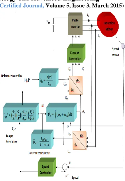
[image:4.595.318.533.115.427.2]The main role of the speed controller is to keep the motor speed equal to the speed reference input in steady state and to provide a good dynamic response during transients & the closed loop current control operates the voltage source inverter in current control mode which ensures that the winding current follow same pattern as that reference currents generated from control logic
Fig 7: Basic Vector control block diagram
V. DESIGN OF FUZZY LOGIC CONTROLLER The fuzzy logic controller consists of four blocks, Fuzzification, inference mechanism, knowledge base and Defuzzification
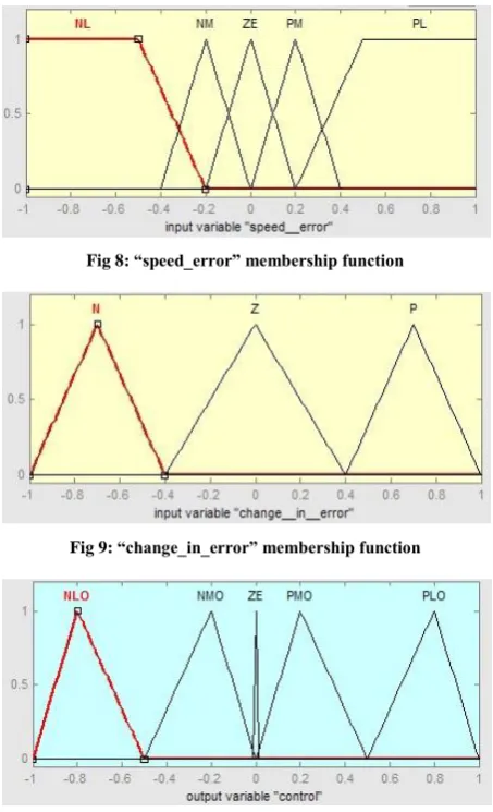
a)Fuzzifications: In this stage the crisp variables of input e(ts) and ce(ts) are converted into fuzzy variables. The fuzzification maps the error and change in error to linguistic labels of fuzzy sets. Membership function is associated to each label with triangular shape which consists of two inputs and one output. The proposed controller uses following linguistic labels NL, NM, ZE, PM, PL. Each of the inputs and output contain membership function with all these five linguistics.
b)Knowledge base and inference stage: Knowledge base
International Journal of Emerging Technology and Advanced Engineering
Website: www.ijetae.com (ISSN 2250-2459,ISO 9001:2008 Certified Journal, Volume 5, Issue 3, March 2015)
605
c) Defuzzification: This stage introduces different methods that can be used to produce fuzzy set value for the output fuzzy variable. Defuzzification interface performs the following functions.
1. A scale mapping, which converts the range of values of output variables into corresponding universe of discourse.
2. Defuzzification, which yields a non-fuzzy control action from an inferred fuzzy control action.
[image:5.595.51.278.317.690.2]Each universe of discourse is divided into seven over lapping fuzzy sets: NL (Negative Large), NM (Negative Medium), ZE (Zero), PM (positive Medium), and PL (Positive Large) [3]. Each fuzzy variable is a member of the subsets with a degree of membership μ varying between 0 (non-member) and 1 (full-member).
Fig 8: “speed_error” membership function
Fig 9: “change_in_error” membership function
Fig 10: “control” membership function
TABLE1 FUZZY RULE BASE
NL NM ZE PM PL
N NLO NMO PMO PLO PLO
Z NLO NMO ZE PMO PLO
P NLO NLO NMO PLO PLO
Rule Statement:
1. If (speed__error is NL) and (change__in__error is N) then (control is NLO)
2. If (speed__error is NM) and (change__in__error is N) then (control is NMO)
3. If (speed__error is ZE) and (change__in__error is N) then (control is PMO)
4. If (speed__error is PM) and (change__in__error is N) then (control is PLO)
5. If (speed__error is PL) and (change__in__error is N) then (control is PLO)
6. If (speed__error is NL) and (change__in__error is Z) then (control is NLO)
7. If (speed__error is NM) and (change__in__error is Z) then (control is NMO)
8. If (speed__error is ZE) and (change__in__error is Z) then (control is ZE)
9. If (speed__error is PM) and (change__in__error is Z) then (control is PMO)
10. If (speed__error is PL) and (change__in__error is Z) then (control is PLO)
11. If (speed__error is NL) and (change__in__error is P) then (control is NLO)
12. If (speed__error is NM) and (change__in__error is P) then (control is NLO)
13. If (speed__error is ZE) and (change__in__error is P) then (control is NMO)
International Journal of Emerging Technology and Advanced Engineering
Website: www.ijetae.com (ISSN 2250-2459,ISO 9001:2008 Certified Journal, Volume 5, Issue 3, March 2015)
606
15. If (speed__error is PL) and (change__in__error is P) then (control is PLO)VI. MATLABSIMULATION
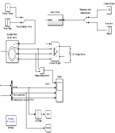
A. MATLAB Simulation of Indirect Vector Control Induction Motor based on PI controller:
[image:6.595.318.549.232.491.2]The simulation of IVCIM using PI controller was done as diagram shown in the below figure. The IM was simulated at four various conditions. First at reference speed of 120 and no load. Second at speed varied from 120 to 160 after a time t1(s) and no load. Third by varying the load after a time t2(s) and keeping the speed at 120. The final condition being variation of load at a time t2(s) and variation of speed from 120 to 160 after a time t1(s). The feedback is given to summer, output of summer error given to PI controller which change the in output for better result.
Fig 11: Simulation Block Diagram of PI controller
B. MATLAB Simulation of Indirect Vector Control
Induction Motor based on Fuzzy controller:
The simulation of IVCIM using Fuzzy controller was done as diagram shown in the below figure. The IM was simulated at four various conditions.
[image:6.595.55.277.340.597.2]First at reference speed of 120 and no load. Second at speed varied from 120 to 160 after a time t1(s) and no load. Third by varying the load after a time t2(s) and keeping the speed at 120. The final condition being variation of load at a time t2(s) and variation of speed from 120 to 160 after a time t1(s). Fuzzy logic controller block is used which have two input Speed_Error and rate of change in error and one output.
Fig 12: Simulation Block Diagram of FUZZY controller
VII. EXPERIMENTAL RESULT
A. Performance of Indirect Vector Control IM Using P-I Control:
The performance characteristic of a 50 hp, 460 V, 60 Hz IM, operating at various conditions with a PI speed controller was done and the following where the results:
Case 1: AT NO LOAD AND REFERENCE SPEED OF 120 RAD/S
Speed at first reaches 140 rad/sec and then settles down at reference speed 120 rad/sec.
The speed attains steady state at time t = 2.2s
International Journal of Emerging Technology and Advanced Engineering
Website: www.ijetae.com (ISSN 2250-2459,ISO 9001:2008 Certified Journal, Volume 5, Issue 3, March 2015)
607
Graph 1: Represents Voltage vs TimeGraph 2: Represents Current vs Time Graph 3: Represents Speed vs Time
Graph 4: Represents Electromagnetic Torque vs Time
Case 2: AT NO LOAD AND SPEED VARYING FROM120 RAD/S TO 160 RAD/S
Speed at first reaches 140 rad/sec and then settles down at reference speed 120 rad/sec.
The speed attains steady state at time t = 2.1s
Speed is then varied to 160 rad/s after a time t = 7s. After variation the speed reaches 170 rad/s and then reaches the reference speed 160 rad/s
After changing the reference speed to 160 rad/s the steady state speed is obtained at t = 1.4s
Graph 1: Represents Voltage vs Time Graph 2: Represents Current vs Time Graph 3: Represents Speed vs Time
Graph 4: Represents Electromagnetic Torque vs Time
Case 3: LOAD APPLIED AFTER A TIME T(S) AND REFERENCE SPEED OF 120 RAD/S
Speed at first reaches 140 rad/sec and then settles down at reference speed 120 rad/sec.
The speed attains steady state at time t = 2.1s Then the load is applied after a time t = 14s.
Speed after variation dips to 105 rad/s and then settles to reference speed 120 rad/s
After applying the load the steady state speed is obtained at t = 1.2s
Graph 1: Represents Voltage vs Time Graph 2: Represents Current vs Time Graph 3: Represents Speed vs Time
Graph 4: Represents Electromagnetic Torque vs Time
Case 4: LOAD APPLIED AFTER A TIME T(S) AND SPEED VARYING FROM120 RAD/S TO 160 RAD/S
Speed at first reaches 140 rad/sec and then settles down at reference speed 120 rad/sec.
The speed attains steady state at time t = 2.1s
Speed is then varied to 160 rad/s after a time t = 7s.
After variation the speed reaches 170 rad/s and then reaches the reference speed 160 rad/s
After changing the reference speed to 160 rad/s the steady state speed is obtained at t = 1.4s
Then the load is applied after a time t = 14s.
Speed after variation dips to 150 rad/s and then settles to reference speed 160 rad/s
International Journal of Emerging Technology and Advanced Engineering
Website: www.ijetae.com (ISSN 2250-2459,ISO 9001:2008 Certified Journal, Volume 5, Issue 3, March 2015)
608
Graph 1: Represents Voltage vs TimeGraph 2: Represents Current vs Time Graph 3: Represents Speed vs Time
Graph 4: Represents Electromagnetic Torque vs Time
B. Performance of Indirect Vector Control IM Using FUZZY Control:
The performance characteristic of a 50 hp, 460 V, 60 Hz IM, operating at various conditions with a FUZZY speed controller was done and the following where the results:
Case 1: AT NO LOAD AND REFERENCE SPEED OF 120 RAD/S
Speed at first reaches directly 120 rad/sec and then settles down at reference speed 120 rad/sec thereafter.
The speed attains steady state at time t = 0.8s
Graph 1: Represents Voltage vs Time Graph 2: Represents Current vs Time Graph 3: Represents Speed vs Time
Graph 4: Represents Electromagnetic Torque vs Time
Case 2: AT NO LOAD AND SPEED VARYING FROM120 RAD/S TO 160 RAD/S
Speed at first reaches directly 120 rad/s and then settles down at reference speed 120 rad/sec.
The speed attains steady state at time t = 0.8s Speed is then varied to 160 rad/s after a time t = 7s.
After variation the speed reaches 160 rad/s and subsequently settles at reference speed 160 rad/s
After changing the reference speed to 160 rad/s the steady state speed is obtained at t = 0.6s
Graph 1: Represents Voltage vs Time Graph 2: Represents Current vs Time Graph 3: Represents Speed vs Time
Graph 4: Represents Electromagnetic Torque vs Time
Case 3: LOAD APPLIED AFTER A TIME T(S) AND REFERENCE SPEED OF 120 RAD/S
Speed at first reaches 120 rad/sec and then settles down at reference speed 120 rad/sec.
The speed attains steady state at time t = 1.0s
Then the load is applied after a time t = 14s.
Speed after variation dips to 100 rad/s and then settles to reference speed 120 rad/s
International Journal of Emerging Technology and Advanced Engineering
Website: www.ijetae.com (ISSN 2250-2459,ISO 9001:2008 Certified Journal, Volume 5, Issue 3, March 2015)
609
Graph 1: Represents Voltage vs TimeGraph 2: Represents Current vs Time Graph 3: Represents Speed vs Time
Graph 4: Represents Electromagnetic Torque vs Time
Case 4: LOAD APPLIED AFTER A TIME T(S) AND SPEED VARYING FROM 120 RAD/S TO 160 RAD/S
Speed at first reaches 120 rad/sec and then settles down at reference speed 120 rad/sec.
The speed attains steady state at time t = 0.8s
Speed is then varied to 160 rad/s after a time t = 7s.
After variation the speed reaches 160 rad/s and then reaches the reference speed 160 rad/s
After changing the reference speed to 160 rad/s the steady state speed is obtained at t = 0.6s
Then the load is applied after a time t = 14s.
Speed after variation dips to 140 rad/s and then settles to reference speed 160 rad/s
After applying the load the steady state speed is obtained at t = 0.8s
Graph 1: Represents Voltage vs Time Graph 2: Represents Current vs Time Graph 3: Represents Speed vs Time
Graph 4: Represents Electromagnetic Torque vs Time
VIII. CONCLUSION AND FUTURE SCOPE
The project was successfully modeled and designed using MATLAB/Simulink and its was simulated at various conditions. The two controllers, namely PI and FUZZY were studied and was compared with each other for speed control of indirect vector control of induction motor drive. At different conditions the controller were simulated and their result and data from the motor drive such as motor current, motor torque and speed was obtained at no load and 200 N-m. The load performance of Fuzzy logic controller was better than that of PI controller. Based on simulation results verification, the following conclusions are made:
The Fuzzy logic controller is more robust than the PI and when load disturbances occurred.
The Fuzzy logic controller performance when certain
motor parameters (i.e. current and motor torque) were increased by a factor was still quite good and far better than the PI performance when the same parameters.
The fuzzy logic controller base makes the superior to PI control techniques.
International Journal of Emerging Technology and Advanced Engineering
Website: www.ijetae.com (ISSN 2250-2459,ISO 9001:2008 Certified Journal, Volume 5, Issue 3, March 2015)
610
REFERENCES[1] Rakesh Singh Lodhi and Payal Thakur. Performance & Comparison Analysis of Indirect Vector Control of Three Phase Induction Motor International Journal of Emerging Technology and Advanced Engineering Volume 3, Issue 10, October 2013) [2] Ashutosh Mishra, Prashant Choudhary. Speed Control Of An
Induction Motor By Using Indirect Vector Control.International Journal of Emerging Technology and Advanced Engineering, Volume 2, Issue 12, December 2012)
[3] P.Tripura and Y.Srinivasa Kishore Babu, “ Fuzzy Logic Speed Control of 3 phase Induction Motor Drive ”,World Academy 0f Science, Engineering and, Vol.: 5 2011-12-20 .
[4] Arun Kumar R. Indirect Field Oriented Control of Induction Motor Using Fuzzy Logic, PG Scholar, PED, SELECT, VIT University, Chennai.
[5] S. RAFA L. BARAZANE A. LARABI .Intelligent Control of Induction motor using interval type-2 fuzzy logic, Journal of Electrical Engineering.
[6] Afonso, JoãoL. Fonseca, Jaime C Martins, Júlio S. Couto, Carlos .Fuzzy logic techniques applied to the control of a three-phase induction motor.
[7] Jerry M Mendel .“ Fuzzy Logic Systems for Engineering : A Tutorial “ .
[8] Pabitra Kumar Behera, Manoj Kumar Behera, Amit Kumar Sahoo Comparative Analysis of scalar & vector controlof Induction motor through Modeling &Simulation
[9] P.Tripura and Y.Srinivasa Kishore Babu Fuzzy Logic Speed Control of Three Phase Induction Motor Drive.