4983
WAVELET NEURAL NETWORK-BASED STABILIZER FOR
ELECTRIC POWER SYSTEM STABILITY IMPROVEMENT
1RUDY GIANTO
1Department of Electrical Engineering, Tanjungpura University, Indonesia
E-mail: 1[email protected]
ABSTRACT
The application of adaptive control technique or procedure in designing control coordination of power system stabilizers is presented in this paper. The design is based on the use of a wavelet neural network which adjusts the parameters of the stabilizers to achieve system stability and maintain optimal dampings as the system operating condition and/or configuration changes. The developed wavelet neural network-based adaptive stabilizer is tested with a representative multi-machine power system. The test results show that the proposed adaptive stabilizer can maintain and improve the stability even with the changes of system operating conditions and configurations.
Keywords: Wavelet Neural Network, PSS, Adaptive Stabilizer, Power System, Stability
1. INTRODUCTION
One of the essential criteria for secure system operation is the stability of the power system. On the other hand, it has been known that the system stability can only be maintained if the electromechanical modes of oscillations among interconnected synchronous generators have sufficient damping. Power system stabilizers (PSSs) have been used for many years to improve and maintain the stability of the system electromechanical modes.
In this context, there has been extensive research in the application of PSSs, particularly their control coordination, for achieving optimal damping of electromechanical modes and power system stability improvement [1-9]. In [1-9], control coordination design procedures in off-line environments which lead to fixed-parameter controllers have been reported. However, it is, in general, accepted that there are disadvantages associated with fixed-parameter controllers, even with those obtained by robust design. If the design is based on one particular power system operating condition and configuration, it is possible that the performances of the controllers will deteriorate under other operating conditions or configurations.
With the objective of removing the disadvantages of fixed-parameter controllers, adaptive control techniques applied for power system damping controller design have been developed by some researchers [10-15]. In [10-15], artificial neural networks were proposed for implementing PSS in a single-machine infinite bus system. However,
control coordination among different PSSs in multi-machine power system was not considered in the papers. Furthermore, the changes in system configuration due to contingencies, which have a significant impact on electromechanical mode dampings and system stability, were not discussed in the design procedure.
In [14], MRAS (Model Reference Adaptive System) technique has been utilized for the design of STATCOM and UPFC controllers. The proposed MRAS has been applied to guarantee system stability. However, the stabilizer design proposed in [14] also only dealt with the system load fluctuations. The changes in system configuration were not considered in the paper.
In [15], an adaptive and optimal control coordination scheme for power system damping controllers (including PSSs) has been developed. Central to scheme proposed in [15] is the use of neural network synthesized to give in its output layer the optimal controller parameters adaptive to system operating condition and configuration. By using the adaptive controllers design, the system stability and optimal damping can be maintained even with the changes of system operating condition and/or network configuration. The neural network-based stabilizers proposed in [15] have successfully been applied in enhancing damping of electromechanical oscillations, maintaining stability, and improving dynamic performance of a multi-machine power system.
4984 to neural network, wavelet neural network is also a universal function approximator. However, with smaller network size, wavelet neural network is capable to perform satisfactory and can approximate most functions arbitrarily well. This advantage makes the wavelet neural network more efficient and easier to train.
Therefore, against the above background, the objective of the present paper is to investigate the application of wavelet neural network in designing adaptive control coordination of power system stabilizers for enhancing system stability. The wavelet neural network-based adaptive stabilizer is trained offline with a wide range of credible power system operating conditions and configurations, and therefore, it can identify online the optimal controller parameters. The performance of the adaptive stabilizer in improving power system stability and dynamic performance is validated by eigenvalues analysis and time-domain simulations of the power system.
2. POWER SYSTEM STABILIZER (PSS)
Figure 1 shows the general structure of a PSS [19] which is adopted in this paper. The structure consists of a gain block, a washout, lead-lag blocks and a limiter. A washout term/filter (i.e. with a time derivative operator) in the PSS structure is needed to guarantee that the PSS responds only to disturbances, and does not respond to any steady-state condition, when speed or power is input. Here, the rotor speed is used for the PSS input. The PSS output is added to the exciter voltage error signal and served as a supplementary signal.
Figure 1: PSS control block diagram
The state equation derived by examining the PSS transfer functions can be arranged in the following form:
r p p p p
A x C
x (1)
where xp
xP1 xP2 VPSS
T is the vector of state variables of the PSS; Ap and Cp are matricesthe elements of which depend on the gains (KPSS)
and time constants (TPSS) of the PSS controllers.
3. WAVELET NEURAL NETWORK (WNN)
3.1 Neural Network
Artificial neural networks are composed of elements (which imitate the nerve cells or neurons of the biological nervous system) operating in parallel [20, 21]. The neural network function is determined largely by the connections between the elements. The neural network can be trained to perform a particular function by adjusting the values of the connections (weights) between the elements. The neural network is usually implemented by using electronic components or is simulated in software on a digital computer.
In terms of their architectures, the neural networks can broadly be classified into: (i) the feedforward neural network, and (ii) the recurrent neural network. In feedforward neural network (FNN), the inputs to the neurons in each layer of the network are the output signals from the preceding layer only. A recurrent neural network (RNN) distinguishes itself from a FNN in that it has at least one feedback loop. In RNN, the neurons feed their output signals back to their own inputs (self-feedback) or to the inputs of other neurons.
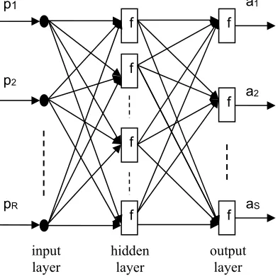
[image:2.612.321.517.497.692.2]The multilayer feedforward neural network or multilayer perceptron, trained by backpropagation algorithm, is the most widely used neural network. Figure 2 shows a feedforward neural network with two layers, the first layer is sigmoid and the second layer is linear. Most practical neural networks have just two or three layers. Four or more layers are used rarely.
Figure 2: Multilayer feedforward neural network
RV
PSS,minV
PSS,max VPSS4 PSS sT 1
3 PSS sT 1
2 PSS sT 1
1 PSS sT 1
PSS sT 1
PSS sT PSS K
aS a2 a1
pR p2 p1
f
f
f
f
f
f
f
input layer
output layer hidden
4985
3.2 Neural Network Training
In neural network training stage, the network parameters (weights and biases) are adjusted to optimize the performance of the neural network [20, 21]. This optimization process consists of two steps. The first step is to determine a quantitative measure of the network performance and usually refers to as performance index. The performance index should be small when the network performs well and large when the network performs poorly. The second step of the optimization process is to search the network parameters in order to reduce the performance index.
Training the multilayer feedforward neural network is usually carried out using optimization methods by which the difference between the network response and target output is minimized. The network is presented with a set of pairs of input and output patterns:
p1,t1
, p2,t2
,...,
pQ,tQ
(2)In (2), pi is an input vector to the network, and ti
is the corresponding target output vector, for i = 1, 2,.…., Q, where Q is the number of training cases. As each input is applied to the network, the network output is formed, and then compared to the target. The algorithm should adjust the network parameters which are the weights and biases in order to minimize the mean squared error:
Q
T Q
1 F
1 i
( )
(δ ti ai) (ti ai) (3)
In (3), δand a are the vectors of network weights and outputs respectively.
3.3 Wavelet Neural Network (WNN)
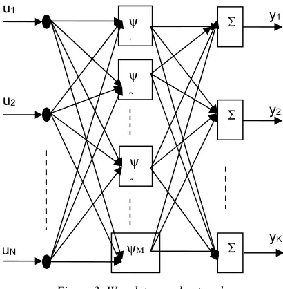
Wavelet neural network is a combination of wavelet and neural network. A wavelet neural network generally consists of a feedforward neural network, with one hidden layer, whose activation functions are based on wavelet functions as shown in Figure 3 [22, 23].
Wavelet function is a class of function that can be used to localize the position and scaling of a function. This wavelet function is defined as:
(u) u t (4)
where and t are the dilation and translation parameters respectively. Wavelet function (4) is known also as mother wavelet. Other wavelets can
[image:3.612.316.521.133.342.2]be generated by changing the dilation and translation of the mother wavelet.
Figure 3: Wavelet neural network
Wavelet Haar, Lemarie, Daubechies, and wavelets derived from Gaussian functions are the most common mother wavelets. However, for function approximation, Gaussian functions-based wavelets are usually used as the activation functions in a wavelet neural network.
As can be seen in Figure 3, the wavelet neural network has M wavelet neurons (wavelons). These wavelons consists of multidimensional wavelet activation functions. Therefore, the output of wavelet neural network of Figure 3 will be the linear combinations of the multidimensional wavelets and is given by:
) , , , (
, , ,
K 2 1 j
y u u u w
y M
1
i ij i 1 2 N j
j
(5)
The training of wavelet neural network is similar to that of neural network. In wavelet neural network training, the parameters y,w,t dan are to be adjusted to minimize the performance index.
4. WNN-BASED STABILIZER
4.1 Basic Principle
There are two key issues that need to be addressed in relation to the design of adaptive stabilizers:
(i) Optimal control coordination.
yK y2 y1
uN u2 u1
4986 It is required to achieve online control coordination of multiple stabilizers in a multi-machine power system. The requirement is to maximize the damping ratio for electromechanical modes for each and every credible system operating condition or configuration.
(ii) Representation of power system configuration. The optimal controller parameters also depend on power system configuration. Due to load demand variation and switching control, including that in protection operation for fault clearance, power system configuration is time-varying during system operation. There is then a need to represent directly and systematically the changes in system configuration in online tuning and coordination of multiple controllers
This section discusses an adaptive control coordination scheme for power system stabilizers that addresses the above two issues. The scheme is based on the use of a wavelet neural network which identifies online the optimal controller parameters. The inputs to the wavelet neural network include the active- and reactive- power of the synchronous generators which represent the power loading on the system, and elements of the reduced nodal impedance matrix for representing the power system configuration. It is, therefore, not required to form and store a range of system models for subsequent online use. The outputs of the wavelet neural network are the parameters of the power system stabilizers which lead to optimal oscillation damping for the prevailing system configuration and operating condition.
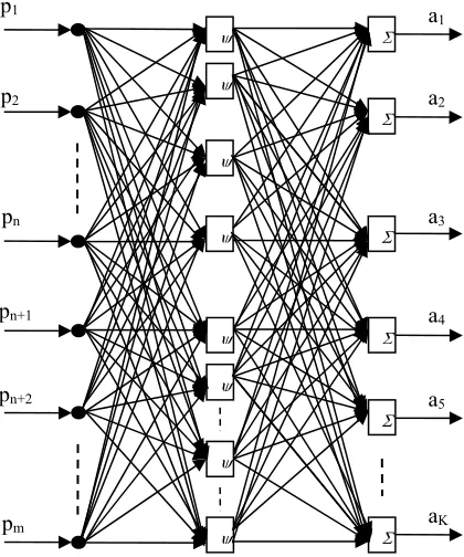
The relationship among the optimal controller parameters and power system operating condition including system configuration is, in general, a nonlinear one. The present paper draws on the key property of the multilayer wavelet neural network, which is that of nonlinear multi-variable function representation. The wavelet neural network is used for the mapping between the power system configurations and/or operating conditions and optimal controller parameters. Figure 4 shows the general structure of the wavelet neural network which is adopted to represent the nonlinear relationship between the optimal controller parameters and power system operating condition together with configuration.
There are two separate sets of nodes in the inputs layer in Figure 4. The first set has n nodes the inputs to which are obtained from the real and imaginary parts of the reduced nodal impedance
[image:4.612.314.524.287.539.2]matrix. These inputs represent power system configuration. If there are Ng generator nodes, the number of input nodes in the first set is Ng2+Ng, when the symmetry in the nodal impedance matrix is exploited. The second set of inputs comprises active- and reactive-power of each and every generator. There will be 2Ng input nodes in the second set. These inputs in the second set represent power system operating condition. Therefore, the total number of inputs is Ng2+3Ng. If the real parts of the reduced nodal impedance matrix are discounted, then the total number of inputs will be 0.5Ng2+2.5Ng. The nodes in the output layer of the neural network structure in Figure 4 give the optimal values of the parameters of PSSs.
Figure 4: Structure of the wavelet neural network
The structure in Figure 4 assumes that there are K controller parameters to be tuned online. On this basis and with the controller in Figure 1, the number of output parameters from the wavelet neural network in Figure 4 is 6Nc, where Nc is the number of PSSs. If only the PSS gains are to be tuned online, than the number of output parameters will be Nc.
4.2 Overall Stabilizer Structure
In Figure 5 is shown the overall structure of which the wavelet neural adaptive controller described in Section 4.1 is a part. For online tuning a3
a2
a1
pn
p2
p1
aK
a5
a4
pm
pn+2
pn+1
4987 of the parameters of PSSs, the inputs required are as follows:
- circuit-breaker and isolator status data - power network branch parameters - generator active- and reactive-power
[image:5.612.86.304.254.442.2]The response of the trained wavelet neural network gives the optimal parameters for the PSSs. The feedback inputs to these controllers are generator speeds, as in the case of fixed-parameter controllers.
Figure 5: WNN-based stabilizer
5. RESULTS AND ANALYSIS
5.1 Power System Structure
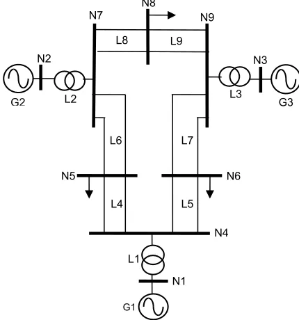
The system in the study is based on the 3-machine 9-node power system of Figure 6 [24]. Initial investigation, where the damping controllers (PSSs) are not included in the system, has been carried out to determine the system oscillation damping and stability without the controllers. Modal analysis used in the investigation shows that there are two electromechanical modes of oscillations.
The investigation also confirms that the system has poor damping. This low system damping indicates poor system dynamic performance and stability. Stabilization measure is, then, required for improving the damping of the oscillations. Therefore, in order to improve the stability, it is proposed to install PSSs in the system (each generator is equipped with PSS).
5.2 Design of the Adaptive Stabilizer
The key requirement is to design an adaptive controller that has the capability of generalizing with high accuracy from the training cases. This requirement is achieved through the wavelet neural network training and testing based on the selection of the training and testing data sets. The wavelet neural network training set should be representative of the cases described by credible system contingencies and changes in system operating conditions.
The possible contingencies of the system in Figure 6 for line outages and load variations are shown in Tables 1 and 2 respectively. The input and output pairs for wavelet neural network training and testing cases are generated from the combinations of these contingencies and operating conditions.
Figure 6: 3-machine 9-node power system
Table 1: Line outages cases
No. Line
1.1 No Line Outage
1.2 One of Line L4
1.3 One of Line L5
1.4 One of Line L6
1.5 One of Line L7
1.6 One of Line L8
1.7 One of Line L9
generator active- and reactive-power generator
speed
power system data base: - line parameters - CB and isolator status
stabilizer
out
puts
ADAPTIVE STABILIZER optimal stabilizer parameter
POWER SYSTEM
STABILIZERS
TRAINED WAVELET NEURAL NETWORK
BUS IMPEDANCE
MATRIX FORMATION
G2
L9 L8
L7 L6
L5 L4
L3 L2
L1
N4
G1
G3 N3 N7
N2
N5
N9
N1 N8
[image:5.612.311.526.329.559.2]4988 For the system in Figure 6, the number of wavelet neural network inputs, as determined on the basis of Section 4, is 18. As mentioned also in Sections 2 and 4, because each PSS controller has 6 parameters, then the number of wavelet neural network outputs will be 18.
[image:6.612.98.299.282.652.2]The load demands in the system are varied in the representative range between minimum and maximum values. It has been taken that the load demands at all nodes follow similar patterns. However, any different patterns of load demand variations, for example, in areas with different time zones, when they arise, can be included in the data set without difficulty.
Table 2: Load variations
No. Load Demand at All Nodes
2.1 100% of Base Load
2.2 101% of Base Load
2.3 102% of Base Load
2.4 103% of Base Load
2.5 104% of Base Load
2.6 105% of Base Load
2.7 106% of Base Load
2.8 107% of Base Load
2.9 108% of Base Load
2.10 109% of Base Load
2.11 110% of Base Load
2.12 111% of Base Load
2.13 112% of Base Load
2.14 113% of Base Load
2.15 114% of Base Load
2.16 115% of Base Load
2.17 116% of Base Load
2.18 117% of Base Load
2.19 118% of Base Load
2.20 119% of Base Load
2.21 120% of Base Load
2.22 121% of Base Load
2.23 122% of Base Load
2.24 123% of Base Load
2.25 124% of Base Load
2.26 125% of Base Load
2.27 126% of Base Load
2.28 127% of Base Load
2.29 128% of Base Load
2.30 129% of Base Load
2.31 130% of Base Load
For each contingency, the reduced nodal impedance matrix for the generator nodes 1 – 3 (including the slack bus) is formed. The power generations including those at the slack bus and the reactive-power which are obtained from load-flow studies and the elements of the reduced nodal
impedance matrix are used as the neural network input data. The optimal controller parameters are also determined for each case using the method described in [5]. These optimal controller parameter values are used as the specified network output data.
In applying the optimal control coordination [5] for training and test data generation, the sum of the squares of the real parts of all of the eigenvalues of the electromechanical modes is maximized, with the constraints that the minimum damping ratio of the electromechanical modes is 0.1. The minimum value of 0.1 is chosen because, as mentioned also in [25, 26], the damping ratio lower than 0.1 is considered unacceptable.
The cases generated from Tables 1 and 2 are sub-divided into the training set and test set. For the training set, line outage cases 1.2 – 1.6 together with load demand variations in cases 2.2 – 2.15, and 2.17 – 2.30 are selected. The remaining cases of line outages and load demand variations in Tables 1 and 2 are used for the test set
In the present work, the performance goal in terms of the error function F() of 0.004 (for training) and 0.006 (for testing) are used. Also, the network size of eight hidden neurons is used in the investigation. These features indicate that by using smaller size network, the WNN-based stabilizer is able to give results with the same accuracy as those obtained by NN-based stabilizer proposed in [15].
5.3 Dynamic Performance of the Stabilizer
Tables 3-6 show the comparisons of modal response characteristics (electromechanical mode eigenvalues, frequencies and damping ratios) between non-adaptive (fixed-parameter) and adaptive (wavelet neural network-based) controllers of the system in Figure 6 for a range of contingencies and operating conditions. For non-adaptive controller, the controller parameters derived from the base case design are used for all of the contingency cases and load change.
4989 Table 4 shows the controller dynamic performances at the load change case. In this case, the load demands at all nodes are increased to 130% of base load while the system configuration remains as that of the base case. With non-adaptive controllers, the damping ratios of the electromechanical modes decrease noticeably in comparison with those in the base case (there is mode with unacceptable damping ratio or lower than 0.1). However, with the adaptive controller, the damping ratios are maintained at the levels similar to those of the base case.
Table 3: Controller dynamic performance at base case
Controller Eigenvalues Freq. (Hz)
Damping Ratio
Non-Adaptive
-2.2582± J10.4730 1,67 0,21 -0.8279± J7.5043 1,19 0,11
Adaptive -2.2185-0.8153±± J10.3355 1,64 0,21
J7.5051 1,19 0,11
Table 4: Controller dynamic performance at load change case
Controller Eigenvalues Freq. (Hz)
Damping Ratio
Non-Adaptive
-1.4320± J10.6266 1,69 0,13 -0.5915± J7.2426 1,15 0,08
Adaptive -2.0189-0.8207±± J11.2149 1,78 0,18
J7.6322 1,21 0,11
[image:7.612.315.522.539.699.2]Further comparison of Table 5 focuses on contingency where one of transmission circuit of L6 is disconnected. The load demands are those in the base case. It can be seen that from Table 5 there is a reduction in the mode damping in comparison with the base case. The damping ratio of this mode is reduced to 0.09, compared to 0.11 in the base case. With the adaptive controller, the damping ratios of all of the electromechanical modes are almost not affected by the outage, in comparison with those in the base case, as indicated in Table 5.
Table 5: Controller dynamic performance at line outage case
Controller Eigenvalues Freq. (Hz)
Damping Ratio
Non-Adaptive
-2.0357± J10.1895 1,62 0,20 -0.6327± J7.0723 1,13 0,09
Adaptive -2.3278-0.7218±± J10.2918 1,64 0,22
J7.1246 1,13 0,10
Table 6 focuses on contingency where one of transmission circuit of L6 is disconnected during higher system load (load demands at all nodes are at 130% of base load). This contingency affects the damping of the electromechanical modes significantly when the non-adaptive controllers are used. The damping ratio of 0.11 in the base case is
now reduced to 0.07. The robustness of the adaptive controller in this outage case is confirmed by the results of Table 6. The controller parameters determined by the trained wavelet neural network are able to adapt to the new system condition for maintaining the modal damping ratios at the levels similar to those in the base case.
Table 6: Controller dynamic performance at line outage and load change case
Controller Eigenvalues Freq. (Hz)
Damping Ratio
Non-Adaptive
-1.3338± J10.3947 1,65 0,13 -0.4491± J6.6472 1,06 0,07
Adaptive -1.8975-0.7415±± J11.0529 1,76 0,17
J6.9765 1,11 0,11
5.4 Time Domain Simulations
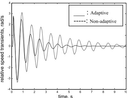
In order to further validate the performance of the wavelet neural network-based stabilizer, time-domain simulations are carried out for the selected contingency case (i.e. load change case). The time-step length of 50 ms is adopted for the simulations. The disturbance that initiates the transients is a three-phase fault on a busbar section connected to node N8 via bus coupler. The fault is initiated at time t = 0.10 second, and the fault clearing time is 0.05 second with the bus coupler tripping.
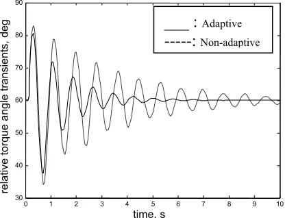
In Figures 7 and 8 are shown the system transients following the disturbance for the selected contingency. It is to be noted that for this contingency, the damping ratio of the weakest mode is 0.08 when the non-adaptive controller is used (see Table 4). As the participations of generators G1 and G2 to this mode are more dominant, then the relative speed and torque angle transients between generators G1 and G2 are used in forming the responses in Figures 7 and 8.
Figure.7: Relative speed (G1-G2) transients
0 1 2 3 4 5 6 7 8 9 10
-4 -3 -2 -1 0 1 2 3 4
time, s
relative speed tra
nsients, rad/s
___ :
Adaptive4990 From the responses in Figures 7 and 8, it can be seen that, with non-adaptive controller, the system oscillation is poorly damped and takes a considerable time to reach a stable condition. With the wavelet neural network-based (adaptive) controller, the system reaches steady-state condition in 5 – 6 s subsequent to the disturbance for the contingency case considered (see Figures 7 and 8).
Figure 8: Relative torque angle (G1-G2) transients
6. CONCLUSION
An adaptive control algorithm and procedure have been derived and developed for online tuning of the PSSs. The procedure is based on the use of a wavelet neural network. For a representative power system, the wavelet neural network-based adaptive stabilizer is trained offline with a wide range of credible power system operating conditions and configurations, and therefore, it can identify online the optimal controller parameters.
The developed adaptive stabilizer has been comprehensively tested to verify its dynamic performance. Both eigenvalue calculations and time-domain simulations are applied in the testing and verification. Many comparative studies have been carried out to quantify the improved performance of the adaptive stabilizer in comparison with that achieved with fixed-parameter stabilizers. The results confirm that, by using the wavelet neural network-based stabilizer, the decrease in system dampings and dynamic performances arising from the use of fixed-parameter stabilizers will be removed and the system stability is improved. It is also to be noted that with smaller size network, the performance of the proposed stabilizer is similar to that of the NN-based stabilizer.
ACKNOWLEDGEMENTS:
The author would like to express special appreciation to the Ministry of Research, Technology and Higher Education of Indonesia (KEMENRISTEK DIKTI INDONESIA) for funding the research reported in this paper (CONTRACT NO.107/SP2H/LT/DRPM/IV/2017).
REFERENCES:
[1] Chaudhuri, B., Korba, P., Pal, B.C., “Damping Controller Design Through Simultaneous Stabilization Technique”, Proceedings of WAC 2004, Vol.15, 2004, pp.13-18.
[2] Majumder, R., Chaudhuri, B., El-Zobaidi, H., Pal, B.C., Jaimoukha, I.M., “LMI Approach to Normalised H-Infinity Loop-Shapping Design of Power System Damping Controllers”, IEE Proc. Gener. Transm. Distrib., Vol.152, No.6, 2005, pp.952-960.
[3] Nguyen, T.T., Gianto, R., “Application of Optimization Method for Control Co-ordination of PSSs and FACTS Devices to Enhance Small-Disturbance Stability”, Proceedings of the IEEE PES 2005/2006 Transmission and Distribution Conference & Exposition, 2006, pp.1478-1485.
[4] Nguyen, T.T., and Gianto, R.: “Stability improvement of electromechanical oscillations by control co-ordination of PSSs and FACTS devices in multi-machine systems”, Proceedings of the IEEE PES GM 2007, June 2007, pp. 1-7.
[5] Nguyen, T.T., Gianto, R, “Optimisation-Based Control Co-ordination of PSSs and FACTS Devices for Optimal Oscillations Damping in Multimachine Power System”, IET Gener. Transm. Distrib., Vol.1, No.4, 2007, pp.564-573.
[6] Nguyen, T.T., Gianto, R, “Optimal Design for Control Co-ordination of PSSs and FACTS Devices with Controller Saturation Limits”, IET Gener. Transm. Distrib., Vol.4, No.9, 2010, pp.1028-1043.
[7] Abd-Elazim, S.M. Ali, E.S., “Optimal PSS Design in a Multimachine Power System Via Bacteria Foraging Optimization Algorithm”, WSEAS Transactions on Power Systems, Vol.8, No.4, 2013, pp.186-196.
[8] Ali, E.S., “BAT Search Algorithm for Power System Stabilizers Design in Multimachine System”, WSEAS Transactions on Power Systems, Vol.10, 2015, pp.230-239.
[9] Gianto, R, “Application of TCSC in Enhancing Dynamic Performance of Interconnected Multimachine Power System”,
0 1 2 3 4 5 6 7 8 9 10
30 40 50 60 70 80 90
time, s
relative torque a
ngle transients, deg
___ :
Adaptive4991 International Journal on Electrical Engineering and Informatics, Vol.8, No.4, 2016, pp.787-801.
[10] Segal, R., Kothari, M.L., Madnani, S., “Radial Basis Function (RBF) Network Adaptive Power System Stabilizer”, IEEE Trans. Power Syst., Vol.15, No.2, 2000, pp.722-727.
[11] Chaturvedi, D.K., Malik, O.P., Kalra, P.K., “Generalised Neuron-Based Adaptive Power System Stabiliser”, IEE Proc. Gener. Transm. Distrib., Vol.151, No.2, 2004, pp.213-218. [12] Huma, Rafi, K.M., Kumar, P., “Artificial
Neural Network Based Self-Tuning Adaptive Power System Stabilizer”, International Journal of Advance Research in Science and Engineering, Vol.2, No.5, 2013, pp.166-175. [13] Memon, A.P. et al., “Selection of Suitable
Feedforward Neural Network Based PSS for Excitation Control of Synchronous Generator”, J. Basic Appl. Sci. Res., Vol.4, No.7, 2014, pp.126-139.
[14] Hemmati, R., Koofigar, H., Ataei, M., “Optimal Adaptive Controller Based on STATCOM and UPFC”, Journal of Electrical Engineering Technology, Vol.11, No.5, 2016, pp.1057-1062.
[15] Nguyen, T.T., Gianto, R., “Neural Networks for Adaptive Control Coordination of PSSs and FACTS Devices in Multimachine Power System”, IET Gener. Transm. Distrib., Vol.2, No.3, 2008, pp.355-372.
[16] Harkouss, Y., et al.: ‘A New Algorithm for Structure Optimization of Wavelet Neural Networks’, Int. J. of Computer Science Issue, Vol.8, No.2, 2011, pp. 108-117.
[17] Abdulkader, W.K., “Two Activation Functions Wavelet Networks for the Identification of Function High Nonlinearity”, Int. J. of Engineering and Computer Science, Vol.12, No.4, 2012, pp. 81-88.
[18] Alexandridis, A.K., and Zapranis, A.D., “Wavelet Neural Networks: A Practical Guide”, Elsevier Neural Networks, Vol.42, 2013, pp. 1-27.
[19] Mithulananthan, N., Canizares, C.A., Reeve, J., Rogers G.J. Comparison of PSS, SVC, and STATCOM Controllers for Damping Power System Oscillations. IEEE Trans. Power System, 2003; 16(2): 786-792.
[20] Demuth, H.B. Beale, M. Neural Network Toolbox User’s Guide: For Use With MATLAB (Version 4). The Math Works, Inc., 2004.
[21] Hagan, M.T., Demuth, H.B., Beale, M., “Neural Network Design”, PWS Publishing Co., Boston, 1996.
[22] Iyengar, S.S., Cho, E.C., Phoha, V.V., “Foundations of Wavelet Networks and Applications”, CRC Press, Florida, 2002. [23] Veitch, D., “Wavelet Neural Networks and
Their Applications in the Study of Dynamical Systems”, Dissertation, University of York UK, 2005.
[24] Anderson, P.M., Fouad, A.A., “Power System Control and Stability”, Wiley-IEEE Press, New Jersey, 2003.
[25] Pourbeik, P., Gibbard, M.J., “Simultaneous Coordination of Power System Stabilizers and FACTS Device Stabilizers in a Multimachine Power System for Enhancing Dynamic Performance”, IEEE Trans. Power Syst., Vol.13, No.2, 1998, pp.473-479.