ISSN: 1992-8645 www.jatit.org E-ISSN: 1817-3195
592
INTEGRATION OF DISTRIBUTED GENERATION TO UPQC
WITH UNIT VECTOR THEORY
1
N. C. KOTAIAH, 2K. CHANDRA SEKHAR
1
Associate Professor, Department Of Electrical & Electronics Engineering,, R.V.R & J.C.College of Engineering, Chowdavaram, Guntur, A.P, India.
2
Professor, Department Of Electrical & Electronics Engineering, R.V.R & J.C.College of Engineering, Chowdavaram,, Guntur, A.P, India
E-mail: [email protected]
ABSTRACT
Power system quality is very much important in present days due to increasing non-linearity in the system. Many compensating devices were developed to improve power quality in the power system. Unified power quality conditioner is one of the FACTS devices that can effectively improve power quality. This paper discusses the integration of distributed generation (DG) to Unified Power Quality Conditioner (UPQC). DG delivers power to system and also stabilizes the DC link capacitor in UPQC. Unit vector control strategy was used to control the UPQC. While transferring active power to the system, DG integration gives stability to power system. Results were given when DG was not integrated to the system and when DG was integrated to the system. Results were also shown if DG was integrated to the system with variable load condition. THDs were shown for source current and load current showing how effective the UPQC works for improving power quality.
Keywords: UPQC, Power Quality, Distributed Generation, Integration, DC Link.
1. INTRODUCTION
Power quality is the major constraint in power sector in these modern days due to increase in variety of load natures. Industrial loads and commercial loads use majority of non-linear natured loads. Advancements in power electronics also lead to developments of house hold devices with non-linear nature. Non-linear natured loads only draws non-linear currents from the source instead of sinusoidal currents distorting the source components. Source components like source currents and voltages might be distorted to varied load nature. Flexible AC Transmission (FACTS) is a subject developed to induce device compensators to increase the power handling capability of the power line and to improve power factor of the system. Custom power devices (CUPS) are the induction of power electronic converters to compensate the source components in power system. Compensation type of custom devices is meant for compensation of source components like voltage and current.
Shunt compensators, series compensators and combination of series-shunt compensators are types
of compensation type CUPS. UPQC is a compensator meant to compensate voltage, harmonics, power factor and reactive power in the main line of power system. UPQC is a series-shunt combinational compensator addressing almost majority of the power quality issues. UPQC consists of back-to-back voltage source converters coupled with a common DC link capacitor. UPQC while using active power from the capacitor for compensating operation discharges the capacitor. The stiff voltage across DC link is to be maintained for effective compensation through UPQC. A pollution free power generation like distributed generation (DG) can stabilize the voltage across DC link capacitor.
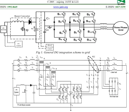
593 S1 S3 S4 S2 S5 S7 S8 S6 S9 S11 S12 S10 Three Phase Grid C1 C2 L Q D v PV System Boost Converter PV output Boost Converter output
Fig 1: General DG integration scheme to grid
N Vsa Vsb Vsc Rs Rs Rs LS LS LS isa isb isc isn Vdvra Vdvrb Vdvrc Lse Rsw Lse
Rsw Rsw
Lse
Saa Sbb Scc
S’aa S’bb S’cc
Sa Sb Sc
S’a S’b S’c
Vdbus
Cdc
Cf
Lf
Rf
Cf Cf
Lf Lf
Rf Rf
Vla Vlb Vlc ila ilb ilc Rla Rlb Rlc Lla Llb Llc n iln Rnl Lnl PCC Vt Linear load
Non linear load Cse Cse Cse
ifn
PV System
PV with Boost converter
Fig.2 Block diagram of the proposed UPQC with DG integration topology
filters can improve the quality in power system for some extent and have some limitations. Thus active filters can be a very good option for the improvement of power quality. FACTS controllers are active filters which use power electronic components for their operation in improving power quality. Series controllers, shunt controllers, combination of series-series, combination of series-shunt are some of the types of FACTS devices depending on their connection. UPQC is a type of FACTS device [11-14] classified under combination of series-shunt which can reduce voltage swell/sag, harmonics and other disturbances in the power system.
This paper discusses the integration of distributed generation (DG) to Unified Power Quality Conditioner (UPQC). DG delivers power to system and also stabilizes the DC link capacitor in UPQC. Unit vector control strategy was used to control the UPQC. While transferring active power to the system, DG integration gives stability to power system.
Results were given when DG was not integrated to the system and when DG was integrated to the system. Results were also shown if DG was integrated to the system with variable load condition.
2. UNIFIED POWER QUALITY
CONDITIONER WITH DG
ISSN: 1992-8645 www.jatit.org E-ISSN: 1817-3195
594
3. OPERATION AND DESIGN OF BOOST CONVERTER
E
i
L
Q
D
v
[image:3.612.74.531.45.740.2]C
R
Fig. 3 Boost DC-DC Converter
T
T/2
1800
T
1T
2T
Fig.4 Timing diagram of Control Signal
During the period of switch ON, inductor charges through switch forming a circuit. Current (IL) flowing through the inductor during a time
period (t) by: ∆
∆ (1)
When switch is OFF, stored energy in inductor discharges and the supply also drives the load, thus increasing the output voltage. The voltage KVL can be written as:
(2)
3.1 Design of Boost Converter:
E
i L
Q
D
v
C R
Fig.5. boost converter
Mode1: T1 ON
E
i L
v C
R
Assume ∆
∆
∆
(3)
Mode 2: DuringT1 off
E
i
Lv
C R
For inductor L1
∆
(4)
Substitute t1=DTs and t2=(1-D)Ts
∆
∆
1
(5)
Total time period
[image:3.612.90.283.102.390.2]595 ∆
(6)
Peak to peak ripple current
1 "
∆ # (7)
∆ $
# (8)
For output capacitor
∆ % % % 0 1' ( % '
Substitute
"
∆ % #%) (9)
Condition for CCM operation. Take worst case ripple ∆ 2
∆ "+ 2 2 2 , 1 + ,2
%- %./ ) #) 0 (10)
Take worst case ripple for capacitor
∆ % 2
2 "'+ 2 ,
1%- %./ )#0 (11)
Specifications
P=15KW; V0=800V; 3= 4 5
6 18.75;
F=20 KHz; R=42.666Ω
1
1 800400 21
1 12
1 12 12
%- %./ 1 2" ,
=1 12> 12 42.666
2 20 10@
42.666
4 20 10@ 0.5333BC
In order to operate in CCM mode
3 %- %./ 1.5999BC
1%- %./ #0 E .FFF 5 0.02GH(approx)
In order to operate in CCM Mode we are choosing
1IJK-. K 200 1%- %./ 4GH
Ripple current is
∆ " L 2 20 10400@ 1.59 10 @
6.2539 ;
Ripple Voltage is
∆ % "'+ 20 1018.75 12@ 4 10 F 7.82
ISSN: 1992-8645 www.jatit.org E-ISSN: 1817-3195
596
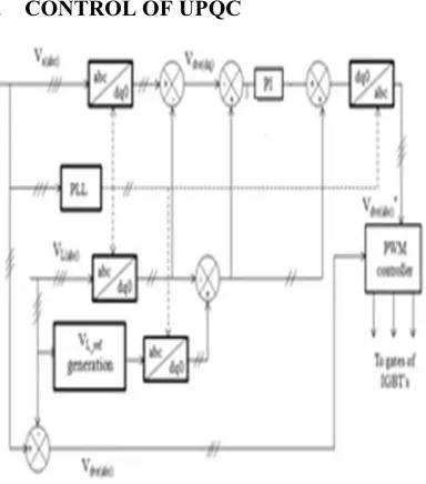
4. CONTROL OF UPQC
Fig.6 Block diagram of the control for UPQC
In UPQC, the series and shunt controllers are controlled with a single controller as shown in figure 6. The source voltage is sent to PLL to obtain the information regarding sine and cos. Simultaneous source voltage is transformed from abc to dq components using parks transformation. DC link voltage is measured from actual value and is compared to reference value. The error voltage signal is sent to PI controller to get voltage magnitude value. The sinusoidal information from PLL is mux to obtain voltage reference wave and is inverse transformed to abc from dq coordinates using inverse parks transformation. Signal is sent to PWM generator to generate trigger pulses to IGBTs of UPQC. Table 1 represents system parameters used for simulation.
[image:5.612.91.530.52.732.2]5. RESULTS AND DISCUSSIONS
Table.1. Simulation Model Parameters
Input voltage 400V
Inductors 1.5999mH
Capacitor 200GF
Resistance 42.666M
5.1 UPQC without DG
Fig 7: Matlab model of UPQC without DG
Fig 8: Results showing source voltage, source current, load current and filter currents of
UPQC without DG
Fig 9: Results showing source voltage, induced voltage through filter, load voltage of
[image:5.612.97.289.96.314.2]597
Fig 10: Results showing power factor of UPQC without DG
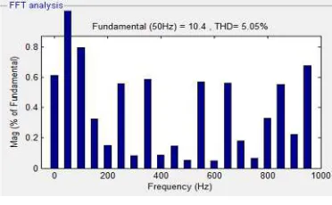
Fig 11: Result of THD in load current for UPQC without DG
Fig 12: Result of THD in source current for UPQC without DG
Figure 7 shows Matlab model of UPQC without DG and figure 8 shows results of source voltage, source current, load current and filter currents of UPQC without DG. Figure 9 is Result showing source voltage, induced voltage through filter, load voltage of UPQC without DG. Figure 10 is result showing power factor of UPQC without DG. Drop in source voltage can be observed from figure 8 and the source current remains almost same throughout the time period. Load current is observed to have harmonics since the connected load is of non-linear type. This non-linear load induces harmonics in the system and they were compensated by the filter induced currents. The sag in source voltage is compensated by inducing voltage to the system through filter.
Figure 11 shows THD in load current for UPQC without DG and figure 12 shows THD in source current for UPQC without DG. THD in load current is 29.8 % high in value since load draws non-linear components and when UPQC is connected the source current distortions are reduced to 5 % maintained nominal.
5.2 UPQC with integration of DG and fixed load
[image:6.612.331.522.437.650.2]ISSN: 1992-8645 www.jatit.org E-ISSN: 1817-3195
598
Fig 14: Results showing source voltage, source current, load current and filter currents of UPQC with
[image:7.612.94.523.59.391.2]DG and fixed load condition
Fig 15: Results showing power factor of UPQC with DG and fixed load condition
[image:7.612.101.309.408.527.2]Fig 16: Result of active power in source and load for UPQC with DG and fixed load
Fig 17: Result of reactive power in source and load for UPQC with DG and fixed load
Fig 18: Result of THD in load current for UPQC with DG and fixed load
Fig 19: Result of THD in source current for UPQC with DG and fixed load
Figure 13 shows Matlab model of UPQC with DG fixed load and figure 14 shows results of source voltage, source current, load current and filter currents of UPQC with DG fixed load. It can be observed the source voltage and current are well in shape indicating no harmonic content due to the presence of UPQC. Load current contains harmonics as the load is of non-linear type. The harmonics induced by the load are compensated by filter currents shown. Figure 15 is result showing power factor of UPQC with DG fixed load. Power factor is maintained nearer to unity as there is no phase difference between source voltage and current. Figure 16 is result showing active power of both source and load of
UPQC with DG fixed load. Figure 17 is result showing reactive power of both source and load of UPQC with DG fixed load.
[image:7.612.336.522.411.526.2]599
[image:8.612.84.525.57.683.2]5.3 UPQC with integration of DG and variable load
Fig 20: Matlab model of UPQC with DG and variable load
Fig 21: Results showing source voltage, source current, load current and filter currents of UPQC with
[image:8.612.340.514.232.405.2]DG and variable load condition
[image:8.612.94.295.348.650.2]Fig 22: Results showing power factor of UPQC with DG and variable load condition
Fig 23: Result of active power in source and load for UPQC with DG and variable load
[image:8.612.338.516.453.651.2]ISSN: 1992-8645 www.jatit.org E-ISSN: 1817-3195
600
[image:9.612.89.528.64.179.2]Fig 25: Result of THD in load current for UPQC with DG and variable load
Fig 26: Result of THD in load current for UPQC with DG and variable load
Figure 20 shows Matlab model of UPQC with DG variable load and figure 21 shows results of source voltage, source current, load current and filter currents of UPQC with DG variable load. Load variation can be observed with increase in load current. Though the load is increased the source current and voltage remains same at 10A and 320V respectively. Load initially was the 10A and after load is increased it demanded at 20A. this increased load demand was met by DG through filter. Figure 22 is Result showing power factor of UPQC with DG variable load. No phase shift was observed between source voltage and current thus maintaining power factor nearer to unity. Figure 23 is result showing active power of both source and load of UPQC with DG variable load. Active power demand of the load is increased due to increase in load. Figure 24 is result showing reactive power of both source and load of UPQC with DG variable load which are maintained almost constant even when the load is increased.
Figure 25 shows THD in load current for UPQC with DG variable load and figure 26 shows THD in source current for UPQC with DG. THD in load current is 29.26 % and while UPQC is connected the source current distortions are reduced to 5.35 % maintaining nominal value.
6. CONCLUSION
Power system quality is
extremely abundant vital in these days because of increasing non linearity within the system. Several compensating devices were developed to enhance power quality within the power grid. Unified power quality conditioner is one in many of the FACTS devices that may effectively improve power quality. This paper discusses the combination of distributed generation (DG) to Unified Power Quality Conditioner (UPQC). DG delivers power to system and conjointly stabilizes the DC link capacitance in UPQC. Unit vector management strategy was
accustomed to control the
UPQC. Whereas transferring active power to the system, DG integration offers stability to power
grid. Results were explained once for DG wasn't integrated to the system and once DG was integrated to the system. Results were conjointly shown if DG was integrated to the system with variable load condition. THDs were shown for supply current and load current showing however effective the UPQC works for rising power quality.
REFRENCES:
[1] M. Bollen, Understanding Power Quality Problems. Piscataway, NJ, USA: IEEE, 2000, ch. 1, pp. 1–35.
[2] H. Fujita and H. Akagi, “Voltage-regulation performance of a shunt active filter intended for installation on a power distribution system,”
IEEE Trans. Power Electron., vol. 22, no. 3, pp. 1046–1053, May 2007.
[3] K.Kowalenko, Distributed Power Offers an Alternative to Electric Utilities, vol. 25, IEEE Press, Piscataway, NJ, 2001.
[4] F. Blaabjerg, Z. Chen, S.B. Kjaer, Power electronics as efficient interface in dispersed power generation systems, IEEE Trans. Power Electron. 19 (September (5)) (2004) 1184–1194. [5] M. Aredes, K. Heumann, and E. Watanabe, “An universal active power line conditioner,” IEEE Trans. Power Del., vol. 13, no. 2, pp. 545–551, Apr. 1998.
[6] K. Dai, P. Liu, G. Wang, S. Duan, and J. Chen, “Practical approaches and novel control schemes for a three-phase three-wire series– parallel compensated universal power quality conditioner,” in Proc. IEEE APECExpo., 2004, vol. 1, pp. 601–606.
[7] H. Fujita and H. Akagi, “The unified power quality conditioner: The integration of series and shunt-active filters,” IEEE Trans. Power Electron., vol. 13, no. 2, pp. 315–322, Mar. 1998.
601 neural networks, ”IEEE Trans. Ind. Electron., vol. 53, no. 2, pp. 614–623, Apr. 2006.
[9] F.Z. Peng, Editorial: Special issue on distributed power generation, IEEE Trans. Power Electron. 19 (September (5)) (2004) 1157– 1158.
[10] T.S. Perry, Deregulation may give a boost to renewable resources, IEEE Spectr. (January) (2001) 87.
[11] Hideaki Fujita and Hirofumi Akagi, the Unified PowerQuality Conditioner: The Integration of Series- andShunt- Active Filters, IEEE Tran. Power Electronics,vol. 13, no.2, Mar. 1998, pp.315-322.
[12] Fang ZhengPeng, George W. Ott Jr., and Donald J.Adams,“Harmonic and Reactive Power Compensation Basedon the Generalized Instantaneous Reactive PowerTheory for Three-Phase Four-Wire Systems, IEEETrans,Power Electronics, vol.13, no.6, Nov. 1998,pp. 1174-1181.
[13] N. Kumarasabapathy and P. S. Manoharan, MATLAB Simulation of UPQC for Power Quality Mitigation Using an Ant Colony Based Fuzzy Control Technique, Scientific World Journal, Hindawi Publishing Corporation, Volume 2015, pp 1-9.