University of Huddersfield Repository
Mian, Naeem S., Fletcher, Simon, Longstaff, Andrew P. and Myers, Alan
FEAbased design study for optimising nonrigid error detection on machine tools
Original Citation
Mian, Naeem S., Fletcher, Simon, Longstaff, Andrew P. and Myers, Alan (2015) FEAbased design
study for optimising nonrigid error detection on machine tools. In: Laser Metrology, Machine
Tool, CMM & Robotic Performance (LAMDAMAP), 17th 18th March, 2015, Univeristy of
Huddersfield.
This version is available at http://eprints.hud.ac.uk/id/eprint/24282/
The University Repository is a digital collection of the research output of the
University, available on Open Access. Copyright and Moral Rights for the items
on this site are retained by the individual author and/or other copyright owners.
Users may access full items free of charge; copies of full text items generally
can be reproduced, displayed or performed and given to third parties in any
format or medium for personal research or study, educational or notforprofit
purposes without prior permission or charge, provided:
•
The authors, title and full bibliographic details is credited in any copy;
•
A hyperlink and/or URL is included for the original metadata page; and
•
The content is not changed in any way.
For more information, including our policy and submission procedure, please
contact the Repository Team at: [email protected].
FEA-based design study for optimising
non-rigid error detection on machine tools
N.S. Mian, S. Fletcher, A.P. Longstaff, A. Myers
Centre for Precision Technologies, University of Huddersfield,
Queensgate, Huddersfield HD1 3DH, UK
Abstract
Non-rigid-body behaviour can have a considerable effect on the overall accuracy performance of machine tools. These errors originate from bending of the machine structure due to change in distribution of its own weight or from movement of the workpiece and fixture. These effects should be reduced by good mechanical design, but residual errors can still be problematic due to realistic material and cost limitations. One method of compensation is to measure the deformation directly with sensors embedded in a metrology frame. This paper presents an FEA-based design study which assesses finite stiffness effects in both the machine structure and its foundation to optimise the sensitivity of the frame to the resulting errors. The study results show how a reference artefact, optimised by the FEA study, can be used to detect the distortion.
1
Introduction
Geometric errors are also known as rigid-body errors as they are assumed to exist without any specified loading conditions. In reality, the finite stiffness of the machine tool structure can lead to non-rigid effects or load induced errors. These result from factors such as inertia, machine and workpiece mass or cutting forces. These errors vary with different configurations, speed, cutting and loading conditions. [3, 5-8]. The overall effect of these errors is generally small compared to geometric errors but they can become more significant on larger machines and structural configurations having moving workpieces or stacked axes. They can also be the dominant residual error once the systematic geometric errors have been reduced using the standard compensation features available in most modern numerical control systems. The residual uncompensated non-rigid errors are typically due to:
Laser Metrology and Machine Performance XI
Mass of the work piece: Adding a component to the machine table produces a change of loading of the machine structure, movement of the axis during machining will cause a change in deformation.
Cutting loads: The cutting process introduces loading into the machine structure. Taking deep cuts into the workpiece can produce large errors. However, high accuracy is not normally required during heavy cuts.
Cutting tool mass: Single tool mass should not provide excessive loading of the structure. However, multiple tool turrets introduce concentrated loading onto the headstock, causing extra loading close to the point of machining. Fixture stiffness: The stiffness of fixtures is usually relatively high compared
to the more complex machine tool structure. However, this may not be true, as work holding and fixture design becomes increasingly complex and less material is used for clamping.
There are a number of methods which can be used to eliminate these errors, such as better selection of the cutting speeds, feedrate and depth of cut that can reduce cutting load errors. Mechanical adjustments and pre-loading of the structural elements could reduce excessive and uneven loading problems by even distribution of the mass. Fixture stiffness relies on good design as well as cutting parameters. Other sources are fundamental to the operation of the machine tool and cannot be greatly influenced by the user. Some prevention can be achieved by controlling mass distribution such as keeping workpiece and fixture mass in the middle of the table to minimise cantilever effects.
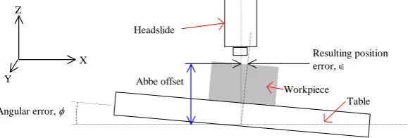
[image:3.595.103.393.460.558.2]Non-rigid errors manifest themselves as small angular errors that change as a result of one or more axes moving, but they can be significant depending on the machine, required tolerances, etc. How angular errors affect volumetric accuracy is sometimes misunderstood.
Figure 1 shows that as the headslide of a machine moves away from the table, the resultant error, , increases. The distance from the centre of rotation to the tool/workpiece interface is called the ‘Abbe’ offset.
Figure 1: Effect of angular rotation of a machine tool table The effect described can be represented by the simple equation:
Z
Y X
x
( )
Resulting position error,
Angular error,
Headslide
X Z
Table
Y Abbe offset
Workpiece
Equation 0-1
Using this equation, a 5arc-second pitch error (rotation of the X axis about the Y axis) will result in 24m of error over 1m. On large machines, the angular effects can be amplified considerably [1].
The importance and effects of non-rigid errors on machine tools have been investigated and researchers [2] have drawn attention towards the significance of their consideration. In research conducted by Longstaff et al [3], the unloaded moving elements of a Beaver 3-axis Vertical Machining Centre (VMC), were incremented along their axes and measurements were conducted to obtain the combined geometric and non-rigid error components using a laser interferometer with static data capture at each position. The variation due to loading of the carriages, and hence displacement of the table, were observed as the saddle is moved along its axis. The non-rigid effects on the X axis linear positioning errors obtained indicated a significant 55µm error due to the kinematic linking effects of the movement of table and saddle.
Poxton [4] analysed the loading effects of structural elements of a small VMC using FEA. Gravity was the only load being exerted onto the structural elements during the simulation. The real errors were measured using a conventional laser interferometer for validation purposes. The base-saddle-table assembly exhibited a vector sum of 16µm of non-rigid error and the spindle-carrier-column assembly exhibited a vector sum of 34µm non rigid error which again were significant compared to the general geometric performance of 60µm of that machine. Non-rigid errors are generally thought of as the smallest contribution to inaccuracy by the three major categories of error i.e. geometric errors, thermal errors and consequently there has been relatively limited research into reducing or compensating for them.
The stiffness of the machine tool foundation, the other important aspect, is another very critical area that concerns the overall machining accuracy. Large machines, such as large moving gantry milling machines, are very sensitive to the stiffness of the machine foundation as well as the rigidity of the sub-soil underneath. The published literature [4] suggests the importance of this area. Myers et al [5] presented a novel technique for measuring the static stiffness of machine tool concrete foundations accurately. FEA was used as a prime tool to predict the stiffness of the structure. This work was a continuation of the previous research [6].
Laser Metrology and Machine Performance XI
optimisation and design study tools to aid in this process by running a sequence of scenarios unaided. This tool is ideal for elastic error simulation having multiple influences. The issues of computing power are also reducing with advancements in computing power.
This paper presents data from such design studies which reveal finite stiffness effects in both the machine structure and its foundation including the sub-soil. It further shows how the implementation of multiple scenarios provides additional information about deflections not normally detected. The design study tool is then used for the development and optimisation of a reference artefact incorporated into a new machine structure. The artefact is designed to detect the machine deformation under selected loading conditions. The results show how the reference artefact can be successfully used to detect the distortion and allow the flexibility to alter the design of the machine and foundations accordingly.
2
Machine Model
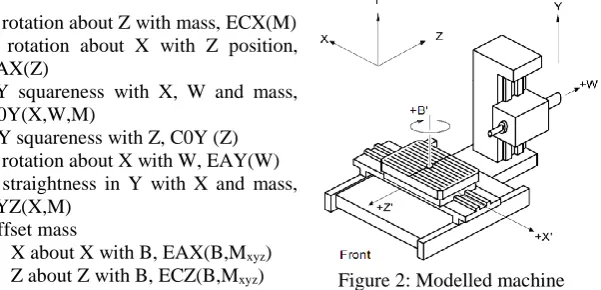
In this study a medium sized 5-axis horizontal milling machine was considered (3m x 3m x 2m approximate axis strokes). The machine configuration (Figure 2) provides production flexibility but has the potential for mass variation. The associated finite stiffness errors are listed below, although these will vary depending on the machine configuration.
• X rotation about Z with mass, ECX(M) • X rotation about X with Z position,
EAX(Z)
• ZY squareness with X, W and mass, A0Y(X,W,M)
• XY squareness with Z, C0Y (Z) • Y rotation about X with W, EAY(W) • Z straightness in Y with X and mass,
EYZ(X,M) • Offset mass
– X about X with B, EAX(B,Mxyz)
– Z about Z with B, ECZ(B,Mxyz)
2.1 Foundation and sub-soil
[image:5.595.108.409.335.480.2]The first consideration for accurate simulation of medium or large machines that rely on the foundation to form part of the structural loop is the sub-soil. In this study the sub-soil beneath the foundation was determined to be a medium to stiff unweathered, over-consolidated clay having a Young’s Modulus of 50MPa. The stiffness is dependent on this value, but also on the depth of the soil before hitting bedrock or other variation in soil type. It is therefore not possible to get an accurate stiffness value without measurement using, for example, a “loaded plate” test. In the absence of a stiffness value, a soil depth of 3m is used to provide sufficient depth for stress to dissipate. The sides are supported with an equivalent elastic support of 25N/µm/m2. The foundation is raised above the soil because the walls
do not normally provide support. The foundation is typical steel reinforced concrete with a Young’s Modulus of 26GN/m2 initially set to 600mm deep. This
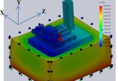
[image:6.595.143.350.225.366.2]was deemed to be the minimum acceptable thickness to be robust against cracking and comfortably accommodate services and fixators. A thickness of 800mm was also included in the work since this was the thickness recommended by a machine builder. An additional consideration for full machine simulation is the method by which the machine is attached to the foundation. In this case BW-Fixatoren fixators were represented as simple blocks with catalogue stiffness of 2.5kN/µm. Figure 3 shows the model of the sub-soil, foundation and CNC machine tool. The Y axis was removed (not relevant to the bed behaviour) and some of the machine structural elements have been simplified to reduce the mesh size, but the same mass and overall rigidity has been maintained.
Figure 3: FEA model of machine, foundation and sub-soil showing displacement in vertical Y direction
2.2 Design study
It is known that the change in weight distribution of the table will cause bending of the bed and could cause squareness errors. A design study was therefore set up to extract displacement of the machine bed in the vertical Y direction from the FEA at a number of different X axis positions and for the two foundation thicknesses of 600mm and 800mm. Figure 4 shows a significantly reduced relative displacement of the ends of the foundation from 85µm to 47µm. The calculated change in XY squareness between the table and column would be reduced from 26µm/m to 15µm/m for the foundation thicknesses respectively. According to the ISO standard 3070 part 1, the result with the minimum thickness is 87% of the allowable squareness tolerance. An additional change in the XY squareness occurs depending on the Z position which was 12µm/m and 7µm/m for the 600mm and 800mm foundation respectively.
Z Y
Laser Metrology and Machine Performance XI
Figure 4: Torsional effect for 600 and 800mm thick foundations 2.3 Guideway straightness
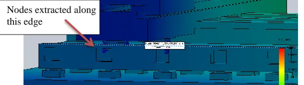
A second design study was run using multiple positions of the Z axis. The table was positioned towards its rightmost limit and the table loaded with the maximum payload of 4000Kg. Initially a perfect support (infinite stiffness foundation) was applied and the Z axis moved to four positions. Deflection of the rolling element guideway was determined using nodes selected along the line shown in Figure 5. The resulting deflections in the vertical Y direction are shown in Figure 6. Localised deflection exceeding 40µm occurs when the rolling element feet are over the foundation bolt recesses, the magnitude of which was the most unexpected result of the work.
Figure 5: Rolling element guideway node selection for deflection measurement The simulation was repeated with the foundation applied as described in the introduction. Figure 7 shows a comparison of the deflection at Z position 620mm with and without the sub-soil. The effect of the foundation deflecting is quite small, at less than 10µm, but it was surprising that it affected such localised distortion. It is expected that the variation will be smaller over the middle of the axis.
Figure 6: Deflection in the vertical Y direction of the Z axis rolling element guideway for different Z axis positions
Figure 7: Deflection in the vertical Y direction of the Z axis rolling element guideway with and without foundation deflection due to sub-soil
3
Metrology frame
One of the most significant distortions on the machine being studied relates to bending of the X axis causing, for example, the angular error ECX depicted by the simulation result shown in Figure 8. Therefore, this structural element was targeted for attaching a measurement system the concept of which was created by Eugen Trapet of ISM3d as part of a joint project (Grant Ref CF-FP 2291122-2). A stable reference strut, shown in Figure 9, provides a reference against which the machine structure can be compared. A pair of displacement measurements at each end, having an offset in the vertical direction, provides the detection of the structural distortion. Nodes were selected where the linear displacement measurement could take place. For one end of the strut they are indicated in Figure 10.
Figure 8: Bending of the X saddle
-50 -40 -30 -20 -10 0 10
-2000 -1000 0 1000 2000
D
e
fl
e
ct
ion i
n Y (µ
m
)
Position along Z guideway (mm)
Z50
Z620
Z1190
Z1760
-50 -40 -30 -20 -10 0 10 20
-2000 -1000 0 1000 2000
D
e
fl
e
ct
ion i
n Y (µ
m
)
Z620 Z620 Soil Diff
[image:8.595.131.368.537.608.2]Laser Metrology and Machine Performance XI
Figure 9: Location of reference strut
Figure 10: Four nodes representing reference strutmeasurement
[image:9.595.88.409.389.496.2]A range of dimensions were simulated using multiple design scenarios, with each configuration requiring multiple positions of the X axis. For the final configuration above, the results showed good sensitivity in the displacement at the optimal nodes to the angular effect at the table. Figure 11 shows the results from two of the lengths include in the study (2.5m and 2m). Minimising the strut length is preferable to reduce material cost, but will potentially reduce sensitivity. The effect at the sensors is only marginally reduced. However, the hysteresis is more than doubled for the shorter length, reducing the accuracy of a position-dependent calculation.
Figure 11: Sensitivity of different reference strut lengths
4
Validation
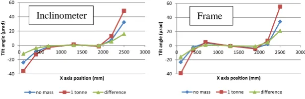
Figure 12 shows the calculated error ECX(M) from the artefact matches the results measured on the machine using an electronic level to 5µrad . The largest effect is from changing mass and this would not normally be detected by a standard compensation system.
2.5m 2.0m
Stable reference strut
Pairs of displacement sensors
Figure 12: Comparison of angular error measured using inclinometer and calculated from the frame results
4.1 Offset workpiece mass
Additional simulations were completed to determine the significance of the mass of the workpiece being offset from the centre of the table and if the strut could be sensitive to the distortion. A design study was run using a medium workpiece weight of 2tonnes offset by 350mm and variation in the positions of both C and X axes as indicated in Figure 13 (left) which gave a total of 29 scenarios to run. The detected changes were converted to rotation and straightness error and shown in Figure 13 (right). As expected, the largest variation is EAX (commonly referred to as roll error or X rotation about X). Although this is nominally tangential to the strut displacement measurement direction, the structural twist and sensor location is sufficient to detect the error.
Figure 13: Offset mass study (Scenario layout for info only) and result
5.
Conclusions
The application of FEA for machine design and analysis is quite common. In this paper, the facility to automate multiple scenarios has been used to identify a range of finite stiffness errors and also to help verify a proposed measuring system for on-line detection of the errors. The effect of sub-soil, foundation thickness and mass variation have been simulated efficiently and show significant effect on the accuracy of the machine including squareness variation approaching typical ISO tolerances and localised straightness deviation of 40µm near typical recesses in the castings. The FEA tools were used to help design a metrology frame to detect the finite stiffness errors for online detection which shows good sensitivity and accurate estimation compared to inclinometer results.
-40 -20 0 20 40 60
0 500 1000 1500 2000 2500 3000
Ti lt an gl e ( µ rad )
X axis position (mm)
ECX measured at the table
no mass 1 tonne difference
-40 -20 0 20 40 60
0 500 1000 1500 2000 2500 3000
Ti lt an gl e ( µ rad )
X axis position (mm)
ECX calculated from beam
no mass 1 tonne difference
-15 -10 -5 0 5 10
0 5 10 15
D et ect ed er ro r ( µ m /µ ra d)
ECX error (µrad)
mECX mEYX mEAX
[image:10.595.86.394.350.472.2]Laser Metrology and Machine Performance XI
6.
Acknowledgements
The authors gratefully acknowledge the support from the European Commission project SOMMACT (Grant Ref CF-FP 2291122-2). The authors also gratefully acknowledge the UK’s Engineering and Physical Sciences Research Council (EPSRC) funding of the EPSRC Centre for Innovative Manufacturing in Advanced Metrology (Grant Ref: EP/I033424/1).
7.
References
1. Fletcher, S., "Computer Aided System for Intelligent Implementation of Machine Tool Error Reduction Methodologies," PhD thesis, School of Computing and Engineering, University of Huddersfield, Huddersfield, 2001.
2. Ford, D.G., Postlethwaite, S.R., Blake, M.D.,’The identification of non-rigid errors in a vertical machining centre’, Proceedings of the Institution of Mechanical Engineers, Part B: Journal of Engineering Manufacture, 213 (6), pp. 555-566. 1999
3. Longstaff, A.P., Fletcher, S., Myers, A., Ford D.G., “Volumetric compensation of machine tools makes geometric errors negligible”, 3rd International Congress on Precision Machining, pp209-216, 2005
4. Poxton, A., Longstaff, A.P., Barrans, S., Myers, A, Fletcher, S., and Pislaru, C., Simulation of the structural elements of a three axis VMC for machine tool error compensation. In: Proceedings of Computing and Engineering Annual Researchers' Conference 2008: CEARC’08. University of Huddersfield, pp. 23-27. ISBN 978-1-86218-067-3
5. Salah, T., Hussain, S.G., IAlAzzawy, W., ‘Machine Tools Foundation Static and Free vibration analyses’, April 2012, WSEAS Transactions on Applied & Theoretical Mechanics; Apr 2012, Vol. 7 Issue 2, p93
6. Myers, A., Barrans, S.M., Ford, D.G., ‘Measurement techniques for determining the static stiffness of foundations for machine tools ‘, Journal of Physics: Conference Series, Volume 13, Issue 1, 1 January 2005, Pages 410-413 7. Myers, A., Ford, D.G., Barrans, S., ‘Finite element analysis of the static stiffness of a foundation for large machine tool’, Laser Metrology and Machine Performance VII - 7th International Conference and Exhibition on Laser Metrology, Machine Tool, CMM and Robotic Performance, LAMDAMAP 2005 8. Dahlström, S., Hu, S.J., Söderberg, R., ‘Identifying variable effects on the dimensional quality of compliant assembly, using computer experiments’, 28th Design Automation Conference; Montreal, Que.; Canada; 2002