2017 2nd International Conference on Artificial Intelligence and Engineering Applications (AIEA 2017)
ISBN: 978-1-60595-485-1
Study on Target Recognition Methods in Velocity
Experiment Using High Speed Camera
QIANWU LI
ABSTRACT
At present in the shooting field experiment, commonly use high-speed camera shoot to projectile or debris flying process, and obtain the speed of moving objects by processing image frame. This method is more simple and efficient than the aluminum foil method, net target method, and can restore the flight path. How to deal with the image frame is the key of this method. For a group of a projectile flight image frame as an example, different classical algorithms are used to deal with the frames. Combine the different methods with the complex characteristics of the experimental environment and improve this method. The results show that the target can be extracted better and clouds, shadows, dust and other noise can be filtered.
KEYWORDS
High speed camera, velocity measurement moving target detection, interface differencing, shooting range experiment.
INTRODUCTION
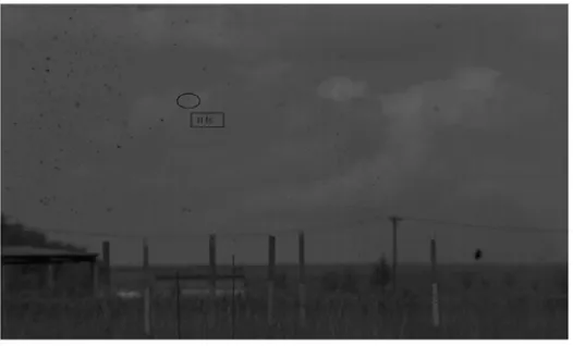
Figure 1. image frame.
At present, the most widely used target recognition methods include background difference method, interface difference method and optical flow method. The optical flow method uses the time domain variation and correlation of the pixel intensity data in the image sequence to determine the "motion" of the respective pixel position, that is, to study the relationship between the change of the image gray scale and the object structure and its motion in the scene. In the shooting range, the gray level conservation assumption of the basic equations of the optical flow field cannot be satisfied due to the occlusion, multi light source, transparency and noise, and the correct optical flow field cannot be solved[1].
The interface difference method is a method for obtaining the contour of a moving object by performing a differential operation on two adjacent frames in the video image sequence, which can be well applied to the case where there are a plurality of moving objects and the movement of the camera. The background difference method is a method for detecting moving objects by comparing the current frame and the background reference model in the image sequence. The performance depends on the background modeling technique that used to detect the moving target fast, accurately and easily, which the key is to get the background image [2].
BACKGROUND DIFFERENCE METHOD
Pretreatment
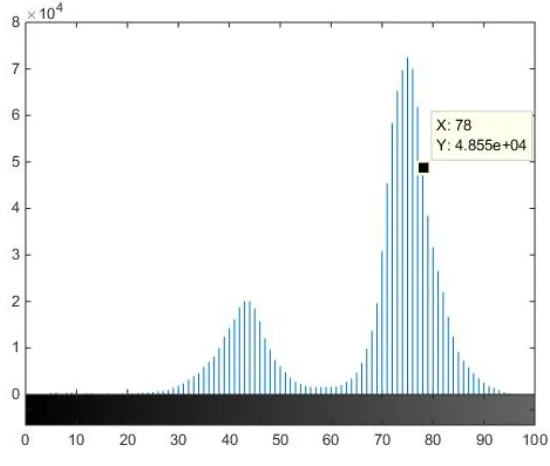
Figure 2. Statistical histogram.
After analyzing the histogram, set the linearization threshold to 0.19 to handle the effects of the ground and the upper right part of the sky during the pretreatment phase.
Background model
Because the image colors, background pixel value distribution in a very short time frame interval is not multi peak, so in the establishment of Gauss model weighted pixel point value obtained is very small, it is easy to tell whether a pixel is foreground or background [4].
K 1 i t i t i t i t i t X XP , * ,, ,
(1)
Among
1 ti t it X 2 1 2 1 t i 2 n t i t i t
i e X
2 1
X i itT
, , / / , / , . , , , INTERFRAME DIFFERENCING
Traditional frame difference method.
little, it is easy to be recognized as noise, so we need to take more frames to experiment.
Assume that the gray values of each pixel of the kth frame and the k-1th frame
are respectively
g
k (i, j) and gk-1(i, j), their difference image is [6]
i j g
i j g
i jPk , k , k1 ,
(2)
Set the threshold to determine the individual pixels, so as to extract the motion area
T j i P 0 T j i P j i g j i M k k k , , , , , ,k
(3)
Method improvement.
Based on the previous experience of improving the three-frame difference method, the five-frame difference method can be used to improve the application of the three frame difference method in the field experiment to a certain extent [7].
The five images after pretreatment are fi2
x,y , fi1
x,y , fi
x,y , fi1
x,y ,
x yfi2 , , through which the difference image is obtained below
x y f
x y f
x yP13 , i , i2 ,
x y f
x y f
x yP23 , i , i1 , P23
x,y fi
x,y fi1
x,y
x y f
x y f
x yP34 , i , i1 ,
x y f
x y f
x yP35 , i , i2 ,
The difference results are subjected to "and" operations
x y P
x y PP1 13 , 35 ,
x y P
x y PP2 23 , 34 ,
The final contour is derived from the OR operation
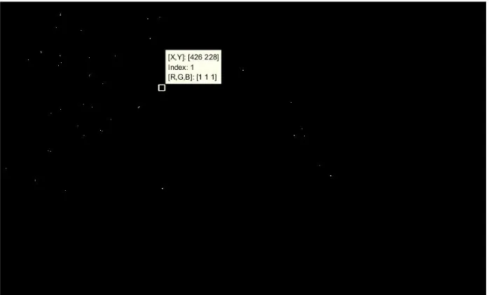
x y P1 P2Figure 3. three frame difference.
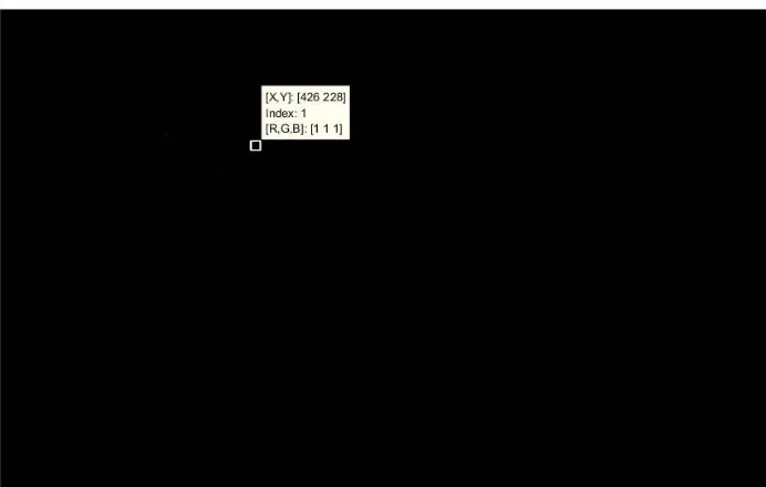
Figure 4. five frame difference.
[image:5.612.163.439.337.513.2]Figure 5. Combined with the background model of the interface difference.
Combined with the background model of the interframe difference
It can be seen that after the pretreatment, block threshold, the background model is established and then the improved inter-frame difference work well. It can remove most of the noise, which achieve the purpose of the target detection.
CONCLUSION
In this paper, combined with several classical algorithms of target detection. Make some improvements according to the actual situation of shooting range experiment. And apply to the image frame processing of speed measurement using high-speed camera.
In this paper, use the histogram to segment the image, then obtain the background model. And extracted the target by the improved frame difference method. It can be seen from the example that the position of the moving projectile can be accurately detected and the result is ideal.
REFERENCES
1. Xiangbin Shi, Meng Wang, Deyuan Zhang, etc. A Moving Target Detection Method for Continuous Optical Flow Tracking [J]. Small microcomputer system, 2014, 35(3): 642-647. 2. Wang L, Hu W, Tan T. Recent developments in human motion analysis [J]. Pattern Recognition,
2003, 36(3): 585-601.
3. Meifeng Gao, Di Liu .Moving object detection with block difference and background difference [J]. Computer Application Research, 2013, 30(1):299-302.
4. Yang Yong. Research on Small Target Detection and Recognition Technology [D]. Institute of Optics and Electronics, Chinese Academy of Sciences, 2006.
6. Zhangping Lu, Defei Kong, Xiaolei Li, etc. A Moving Object Detection Algorithm Based on Difference between Background Difference and Three-frame Difference [J]. Computer Measurement and Control, 2013, 21(12): 3315-3318.