Systems Reference Library
IBM 1130 Utility Routines
This publication provides preliminary specifications for the IBM 1130 Utility Routines. Included is a ,description of the function of each routine and the general requirements for its use.
The utility routines comprise the following:
Input/output routine Dump routines Console routine Loading routines
Each routine is contained in a separate card deck or paper tape.
Copies of this and other IBM publications can be obtained through IBM Branch Offices. Comments concerning the contents of this publication may be addressed to:
IBM, Product Publications Department, San Jose, Calif. 95114
CONTENTS
INPUT jOUTPUT ROUTINE. Card.
Paper Tape
Printer and Typewriter. Control Card
User's Exit
Error Checks 2
Operation. 2
DUMP ROUTINES • 4
Operation. 4
CONSOLE ROUTINE 5
Operation. 5
LOADING ROUTINES 6
PREFACE
The card and paper tape programming systems for the IBM 1130 System including the FORTRAN Com-piler, Symbolic Assembler, Utility routines, and the Subroutine Library comprise the basic IBM-supplied programming systems for use by all 1130 System in-stallations. These programs make it possible to use the IBM 1130 Computing System in a wide range of general engineering applications.
The Utility routines interconnect the system peripheral units, transferring data from one medium to another. They provide the programmer with a versitile tool for performing the repetitive utility functions needed daily by most data processing instal-lations. In addition, they incorporate features that are designed to simplify the reorganization of data libraries.
This publication provides programmers with pre-liminary specifications for the IBM 1130 Utility rou-tines. It includes descriptions of the functions of the routines and general requirements for their use. It
is assumed the reader has a knowledge of computer programming and is familiar with the publications, IBM 1130 Computing System, Principles of Operation
(Form A26-5881) and IBM 1130 Computing System, Input/Output Units (Form A26-5890).
The Utility routines are provided in two different forms: cards and paper tape. When loaded into stor-age, the programs are the same regardless of whether they are entered from cards or paper tape. Each routine is contained in a separate card deck or paper
tape. All references to Control cards in this publica-tion are also applicable in terms of Control records for the paper tape systems. All paper tape records must be punched in Binary Coded Decimal (BCD) character code.
The Utility routines are comprised of the following:
• Input/ Output routine • Dump routines • Console routine • Load routines
Machine Requirements
The minimum machine configuration required for operation of the Utility routines is:
1. IBM 1131 Central Processing Unit, Model 1, with a minimum of 4096 words of core storage. 2. IBM 1442, Model 6, Card Read Punch, or IBM
1054 Paper Tape Reader and IBM 1055 Paper Tape Punch.
Depending upon the utility job to be performed, one or more of the following input/output units may be required.
• IBM 1132 Printer
• IBM 1442 Card Read Punch
This routine has the following input/output capabilities:
Card to Typewriter Card to Printer Card to Paper Tape Paper Tape to Typewriter Paper Tape to Printer Paper Tape to Card Paper Tape to Paper Tape
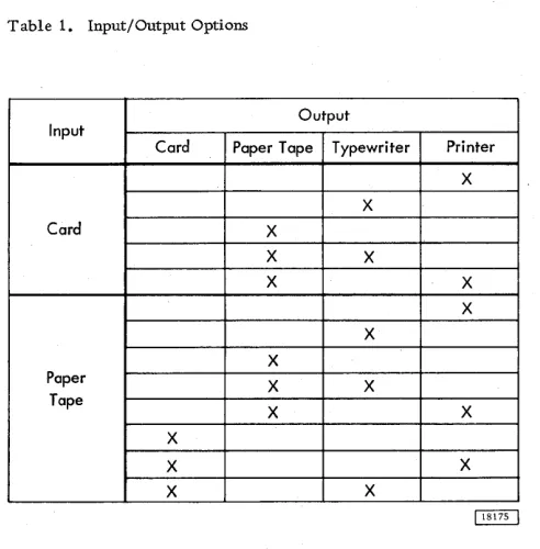
Provisions are made for outputting to more than one output unit from one input unit. Outputs available from a single input are shown in Table 1, which sum-marizes the options of the Input/Output routine.
The utility Input/Output routine makes use of the Conversion and Input/Output subroutines contained in the Subroutine Library. The input and output media handled by the utility routine are listed below. (For a detailed description of each of the referenced codes, refer to the publication IBM 1130 Subroutine Library, Form C26-5929.)
Card
A character is represented by a card column punched in IBM Card (12-bit) code. A fixed length record of data can occupy several cards.
Table 1. Input/Output Options
Input
Output
Card Paper Tape Typewriter Printer
X X
Card X
X X
X X
X X
X
Paper X X
Tape
X X
X
X X
X X
INPUT/OUTPUT ROUTINE
Paper Tape
A character is represented by a column punched in 8-channel paper tape Binary Coded Decimal (BCD) code. Records are separated by a hexadecimal value 80 punch which is represented by the uppermost punch on the tape.
Printer and Typewriter
A character is represented by one print position. Each record will start on a new line at the first print position. A record may extend over more than one line.
CONTROL CARD
A control card must be used to indicate which input/ output operati~m(s) are required and also to convey additional information necessary for the job. Infor-mation in each field should be punched right-justified, with leading zeros. If certain information fields are not applicable, the columns of the fields may be left blank. The control card is divided into three major fields to provide the specifications for:
Input (columns 2-16) Output (columns 18-29)
Additional Print device (columns 30-31) The format of the control card is given in Table 2.
User's Exit
The Input/Output routine provides an exit to allow a user-written subroutine to be executed in combination with the I/O routine. This facility allows, for example, sequence checking of input cards by the user-written subroutine.
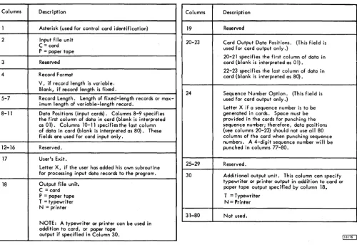
[image:5.612.47.293.457.707.2]Table 2. Control Card Format
Columns Description
1 Asterisk (used for control card identification)
2 Input file unit C = card P = paper tape
3 Reserved
4 Record Format
V, if record length is variable. Blank, if record length is fixed.
5-7 Record Length. Length of fixed-length records or max-imum length of variable-length record.
8-11 Data Positions (input cards). Columns 8-9 specifies the first column of data in card (blank is interpreted as 01). Columns 10-11 specifies the last column of data in card (blank is interpreted as 80). These fields are used for card input only.
12-16 Reserved.
17 User's Exit.
Letter X, if the user has added his own subroutine for processing input data records to the program.
18 Output file unit. C = card P = paper tape T = typewri ter N= printer
NOTE: A typewriter or printer can be used in addition to card, or paper tape
output if specified in Column 30.
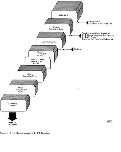
During execution, the link word will contain the address of the word which specifies the address of the input buffer. The link word address must be incre-mented by one (1) to obtain the return address to the I/O routine. The user may call other library sub-routines in his program; in which case, the subrou-tine library deck must follow the user's subrousubrou-tine (see Figure 1).
At execution time, the control card is read in and analyzed. If column 17 of the control card indicates the use of the user's exit, the I/O routine will branch to the Loader routine to load the user's subroutine. After the subroutine is loaded, control will be re-turned to the I/O routine to continue execution.
After an input record is read into the buffer area, the program branches to the user's subroutine. The user's subroutine performs its function and returns to the I/O routine through the link word. The user's subroutine cannot exceed 200 words in length for 4096-word systems or 700 words for larger systems, nor can it alter the length of the input record in any way, though the record may be changed or rearranged.
Columns Description
19 Reserved
20-23 Card Output Data Positions. (This field is used for card output only.)
20-21 specifies the first column of data in card (blank is interpreted as 01).
22-23 specifies the last column of data in card (blank is interpreted as 80).
24 Sequence Number Option. (This field is used for card output only.)
Letter X if a sequence number is to be generated in cards. Space must be provided in the cards for punching the sequence number; therefore, data positions (see columns 20-23) should not use all 80 columns of the card when punching sequence numbers. A 4-digit sequence number will be punched in columns 77-80.
25-29 Reserved.
30 Additional output unit. This column can specify typewriter or printer output in addition to card or paper tape output specified by column 18.
T = Typewriter N = Printer
31-80 Not used.
ERROR CHECKS
The Input/Output routine makes various checks of the control card and the data being processed to ascertain the validity of the operation. Errors are indicated by a message on the typewriter.
OPERATION
The Input/Output routine comprises two phases: 1. Phase 1 is loaded into core storage with the
Library Subroutines and the control card is read and analyzed.
2. Phase 2 is loaded into core storage and the I/O operation is executed.
The input deck arrangement for operation of the Input/ Output routine is shown in Figure 1.
[image:6.615.56.557.81.428.2]Library Subroutine Deck
User's Subroutine
Phase 2 Input/Output
Routine
Control Card For Input/Output
Routine
Library Subroutine Deck
Phase 1 Input/Output
Routine
Relocating Loader
Input To 1130 System
Figure 1. Stacked Input Arrangement for I/O Operations
- - " " . - - - _ Optional
If applicable.
Example: Card-To-Printer
Required When User's Subroutine Calls Library Subroutine That Was Not Called By Phase 1.
Example: Any Functional Subroutine
[image:7.612.56.545.58.670.2]DUMP ROUTINES
These routines are designed to be used to dump all or part of memory on various output units. Normally, a user I s program and/or data will be in memory and
the desired Dump routines will be loaded into memory to perform the required dump.
Dumps between limits are permitted on:
• Punched Card • Typewriter • Printer
Each of the above routines is contained in a sep-arate deck (or paper tape). Each Dump routine util-izes the area in memory o.ccupied by the Relocating or Core-Image Loaders. Thus, if the programmer uses the loader area as a work area, it will be over-laid by the Dump routine.
The limits of the dump (starting and stopping ad-dresses) are entered in hexadecimal form through the Console Entry switches on the console. Any area in memory may be dumped; however, approximately the first 500 words of memory contain the Dump routine itself.
The output of the dump is in either hexadecimal or decimal form. The format of the output is speci-fied by means of a Console Entry switch. If the leftmost switch is on upon entry to the Dump routine, the output will be in hexadecimal form: if it is off, the output will be in decimal form. In hexadecimal form, each 16-bit word is represented by a 4-digit number. If decimal output is desired, each word is outputted as a 5-digit number plus sign (six characters total). However, the address (location) of the first word in each line will always be in hexadecimal form.
Each line of output consists of a 4-digit hexa-decimal address followed by eight words with one space separating each word. This format is used for all three output devices: card, typewriter, and printer.
The output from the eight words may be either eight 4-digit hexadecimal numbers or eight 5-digit decimal numbers. A plus (+) or minus (-) sign will precede each 5-digit decimal number. The address of the leftmost word of each line is in 4-digit hexa-decimal form.
OPERATION
The appropriate card deck or paper tape is loaded to the loader area by means of the Load key. When pro-gram execution begins, the machine stops to allow entry of the starting address through the Console Entry switches. This address should be entered in hexa-decimal form. After the starting address is entered, the program stops again, this time to allow entry of the stopping address of the dump. After the stop ad-dress has been entered. the program will again stop. The leftmost Console Entry switch must be set fo indicate whether hexadecimal or decimal output is required. If the switch is on, output will be in hexadecimal form; if off, it will be in decimal form.
This routine is designed to aid the programmer when debugging his program. While at the machine con-sole the programmer can dump portions of memory by loading a single card which contains the Console routine. The Console routine occupies the first 80 words of memory; it is loaded by means of the Load key.
Memory is dumped by the routine in hexadecimal form starting with the word specified by the Bit switches; dumping continues until the stop key is depressed.
The words are dumped in 4-digit hexadecimal form with a space between each word. The number of characters per line depends upon the margin settings
CONSOLE ROUTINE
of the typewriter. The initial (starting) address is typed on the fir st line.
OPERATION
The user should set the Console Entry switches
to the address from where he wishes dumping to start. The program card should then be placed in the hopper and the Load key pressed. Dumping proceeds in hexa-decimal form; when the user feels he has sufficient information, the Stop key should be pressed to halt the dump. Output will continue upon pressing the
start key.
LOADING ROUTINES
The various user-written programs and routines which make up a complete job are compiled or as-sembled separately. In order to execute a job, all the component programs must be loaded into the com-puter in binary form. This operation can be performed by either of two IBM-supplied loading routines: the Relocating Loader, or the Core Image Loader.
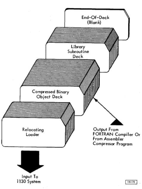
The Relocating Loader loads compressed object programs and subroutines that are in relocatable binary format or in absolute format. Only the sub-routines required by the object program are loaded, and at the completion of the loading process, the loader. branches to the execution address of the object program. The Relocating Loader requires approxi-mately 755 words of core storage during the loading operation. Programs or subroutines cannot be loaded into this area; however, the object program can use words 40 through 755 as a work area. Figure 2 shows the stacked input arrangement to load a program with the Relocatable Loader. An End-of-Deck card (a blank card) must be placed behind the last card of the deck that is to be loaded.
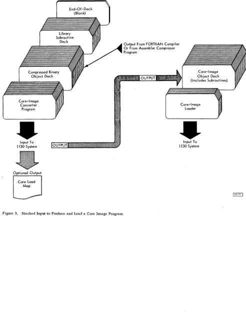
The Core Image Loader loads programs and subroutines that are in core image format. Programs can be converted from relocatable or absolute format to core image format by the Core Image Converter Program. The stacked input arrangement to convert a program to core image format is shown in Figure 3. Also shown is the input arrangement to load the gram. Note that the subroutines required by the pro-gram are included in the core image deck. Thus, a program is converted only once. Thereafter, only the
Core Image Loader is required to load the program for execution. The operation of the Core Image Loader is faster than that of the Relocating Loader as no re-location is necessary and more words (51 compared to 45) are included in each compressed card. The
Relocating Loader
Input To 1130 System
End-Of-Deck (Blank)
Output From
FORTRAN Compiler Or From Assembler Compressor Program
Figure 2. Stacked Input to Load a Relocatable Program
[image:10.617.308.547.118.436.2]Core-Image Converter
Program
Input To 1130 System
Optional Output
Core Load Map
End-Of-Deck (Blank)
Library Subroutine
Deck
Figure 3. Stacked Input to Produce and Load a Core Image Program
Output From FORTRAN Compiler Or From Assembler Compressor Program
Core-Image Object Deck (Includes Subroutines)
Core-Image Loader
Input To 1130 System
[image:11.615.57.550.55.690.2](26-5931-0
w