RICHARD
v
ANDREE
ASSOCIATE PROFESSOR OF MATHEMATICS UNIVERSITY OF OKLAHOMA
c
-...- I f ' '" .. " \ '
0
..
N G•
•
OAt ..
...
".0t0l .... --\I' .Q\; ...•
•
-,
OtU;t1Q1t"~ .;. ... 1< .. ,'0<" ~ut... ucnooo . . . . 'U
..
"CO Olffhl .. OwI • ~ 0 0 4. • 0 0 &8CMltU ~ aut\lU '-'Sfb&tJTOIt L ~ ItI~ :U·
IlCII'.'" tu.II _ ife» '-'*' QHaAnoe , . . . . "a SfOfJ SINN no-C .~~'
. '. . - " ..,. I ( ,
I
I. • • • • • • • • IoOW1I " ' f " ' . ~ .~.. _ . . . • . . . ',01 ,~..-~J 4«t* , no .. .., , ,
' t ' ' \ '
, ,.' ~ .' ; ' ..
~ MOGt£MMtO NW oa. • 0 0 • • " , . ~ I ( ,. I 0 If • C()trl:ft.Ol ~. DGPUoy ovtut&'W ~ '''0'1
I ~I"O""¥I
..
~.••
~,_ _ ~S1"" I SlO'. ~
, • j
, '
,
.
I
' IO(..IAMI
(OMJI~T!"I
,I,(Cu'-I l U f HUT U$U
-..
. ..I
"
'
.'
I H H ; ( Il
... '
l
'
id
,
~
'
·;1
~ ~., " j~
,
I
J , ' , ' . ' • t., ." '" ( ,It \ t \' .. , '.3 ~: . f .. . _ ... ~ .. ~
~.
.
"
'
.
,
'. \
t
J \'
''
':l!~t.
','
)
'.
J ' \ : . . '~.
, • , • • , _r: ..
' :
,
'
rW
, Ii •• , ' .. ~ • " f , , ; . " , ' , . ' • -elf!" ~-iJ~!) ,
... _, _ _ .. ... ... " . ' " 't. ~" . ." ~' ir
"" '* - ;. 4'~! /~
RICHARD V. ANDREE
ASSOCIATE PROFESSOR OF MATHEMATICS UNIVERSITY OF OKLAHOMA
U U U 11 ;J
n
I]HOLT, RINEHART AND WINSTON, INC.
II II I I I I
I I I I
I II
II I
Dedication
I I I I
I III
II II I
1111"
III
I I II III
I II10000010000010000000111000000000100000110010000001000001000000000110000000000000
1 2 3 4 5 6 7 8 9 1011121314151617181920212223242526 272829 JO 313233343536 37 38 39 40414243« 45 46 47 48 49 50 5152535455565158596061626364656667686970717213747576 77 78 79 80
11111111111111111111111111111111111111111111111111111111111111111111111111111111
22222222222222222222122222222222222222222212221222212222222222212222222222222222
13333333333313333333333333313333331333313333333331333333331333333113333131313333
44441444144444444414414444444414444414144444144444444444444144444444444444444444
55555515555151555155555511155555555555551555555155515555555555551551555555155555
616 G 6 6 6 6 6 6 6 6 6 6 6 6 6 S 6 6 6 6 6 6 6 6 6 6 6 6 6666616666666666666 G 6 6 6 6 6116 6 666666666666666666666 77777777771777777777777777777777777771777777777777777777777777777777771777777777
88888888888888888888888 8 ~ 8 8188881888 a 8 8 8 8 8 88888888188888888888888888888888818888 9999999199999919999999199999999999999999919999999999119snl9999999999199999999999
1 2 3 4 5 6 7 8 9 10 11 12 13 14 15 16 17 18 19 20 21 22 2324 25 26 21 23 "~ 111 31 32 33 3435 36 373& 39 (HI 4243 «45 46 47 48 4HD 51 525H4SSS. 51 58 59 61161 6263 64 6566 67 ~8 6l 70 11 ~2 73 14 '5 7S 77 7S 79 80
Copyright @ 1958 by Richard V. Andree
Library of Congress Catalogue Card Number: 58: 12522 Printed in the United States of America
This book is a first introduction to the programming of the IBM 650 computer. Most of the techniques involved are applicable to any medium .. speed or high-speed computer. There are important advantages in programming for a specific machine, available to the reader, rather than with a mythical machine on which it is impossible to check out programs once they are written. The student learns much while debugging his program, and enjoys the thrill of fi-nally seeing it work. These notes can be used whether or not a 650 is available, and they have been used both ways with marked success. Students use flow charts and write actual programs from the very beginning. After half a dozen class sessions, they write simple pro-grams with surprising ease.
These notes are designed to take the neophyte and advance him to the stage where he can use the several available IBM programmer's manuals. Those manuals, are, after all, designed as reference manuals, not as textbooks. These notes provide a text, with suitable problems, and are not intended as a reference manual. The first four chapters are self .. contained. Chap-ters 5 to 9 begin to lean slowly more and more upon the published IBM manuals, which the student is encouraged to consult.
The main purpose of these notes then, is to provide a teachable text on introductory pro-gramming, usable either for self .. study or for classroom work. They have been used in in-tensive one-week courses, in three .. and four .. week courses, and in semester-long courses. They have been used by graduate engineers and by high-school students.
After the first four chapters are completed, the student can be turned loose on his own, although the author much prefers to have the student finish Chapter 5 on the use of SOAP rather than forcing him to write in machine language using five-ten optimization.
Chapter 6, which emphasizes overall principles stressed elsewhere in the book, concludes with a fairly extensive set of real .. life problems, the programming of which may develop con-siderable sophistication on the part of the reader. Chapter 7 discusses the advantages, and also the disadvantages, of interpretive systems and uses the Belllnterpretive System (FLOPS) as an example. Chapter 8 is devoted to compilers, with particular mention of IT and For transit. Since excellent manuals are now (1958) available on the Perlis comp.iler, IT, and on For transit, no attempt is made to discuss these two all-important techniques in complete de-tail. Instead, the reader is given enough insight into For transit to overcome his first fear and to convince him that learning For transit is worthwhile; he is then encouraged to program, turning to the For transit manual as additional help is needed. Chapter 9 is devoted to sev-eral odds and ends with which the student should become familiar if he is seriously interested in programming.
Iv. PREFACE
A convenient teaching device is to make a series of "bug cards" for a .program with which the students are familiar (say Problem 9, Set 1-15). These typical errors can be punched on one-per-card load cards. It is convenient to punch the words "Bug Card" and the problem number in the remarks columns for future use. If a single bug card is placed at the end of the program deck, the false instruction will be loaded over the top of the correct in-struction. The bug card can then be removed without disturbing the main body of the program.
The author will sincerely welcome discussion from users of this book concerning errors, or portions that can be improved in the next edition.
It is my sincere hope that you will find this brief text both helpful and enjoyable.
ACKNOWLEDGMENTS
This list of acknowledgments should include the names of hundreds of students and dozens of colleagues who used these notes in various preliminary forms. That seems im-practical. It would, however, be ungracious not to mention individually those people who have contributed most.
Mr. Frank E. McFarlin, formerly of Oklahoma State University and now with IBM Computer Research and Design Group, Endicott, has helped with the planning of these notes from the beginning and has read the entire manuscript, offering numerous excellent suggestions.
Dr. John Hamblen formerly Director of the 650 Computer Laboratory at Oklahoma State University (currently at the University of Kentucky) and Dr. William Viavant, Director of Scien-tific Computations at the University of Oklahoma have each given encouragement and assist-ance far beyond the call of duty.
Dr. Melvin Shader, Manager, IBM University and Research Institute Program has gra-ciously read the entire manuscript. Many improvements have resulted from his thought-provok-ing suggestions.
Dr. H. A. Meyer, University of Florida and Dr. G. E. Forsythe, U. C. L. A., each made verbal suggestions for which the author is sincerely grateful.
The award for efficiency and elegance in real-life programming goes to the author's wife, who never goes into a loop when her instructions are modified in unanticipated ways. Without her understanding cooperation this book would have been impossible.
To each of the above, and to other colleagues and students, the author expresses sincere thanks.
Norman, Oklahoma
September, 1958
CHAPTER 1 - SIMPLE PROGRAMMING ... .
1- 1 Introduction . 1- 2 What a Computer Is I and Is Not . 1- 3 The IBM 650 .
1- 4 The IBM Card . 1- 5 Word . 1- 6 Drum. 1-7 Accumulator· 1-8 Distributor·
1-9 Instructions . 1 - 10 A Problem . 1 -11 OPeration Codes . 1-12 Logical
Test - NZU . 1- 13 Multiplication. 1-14 New Operation Codes· 1-15 Flow
Charts.
CHAPTER 2 - THE 650 CONSOLE ... 24
2 - 1 Read and Punch . 2 - 2 Power Control Switch. 2 - 3 Display Lights .
2 - 4 Flow of Instructions • 2 - 5 Internal Checking of the 650 . 2 - 6 Load Cards .
2 - 7 Board Wiring for Load Cards . 2 ~ 8 Operating and Checking Lights .
2 - 9 Address Stop . 2-10 Program Start . 2 - 11 Cookbook Directions.
CHAPTER 3 - MORE ADVANCED PROGRAMMING ... 38
3 - 1 Improving Speed • 3 - 2 Stepping Instructions • 3 - 3 Looping and Stepping •
3 - 4 The Count Box • 3 - 5 Another Terminating Technique . 3 - 6 Branching on a
Code Number (Optional) • 3 -7 Scaling. 3 - 8 Scaling in Multiplication.
3 - 9 Division • 3 - 10 (A + B) . C = T. 3 - 11 Optimum Programming.
D'
3 -12 Index Registers (Optional).
CHAPTER 4 - EASY PROGRAMMING VIA SUBROUTINES ... 60
4 -1 Accuracy of Computed Results· 4 - 2 Subroutines· 4 - 3 Partial List of
Available Programs and Subroutines· 4-4 A Problem· 4-5 A Word to Those Who
Will Have Others Write Their Programs • 4 - 6 Floating-point Arithmetic.
CHAPTER 5 - SOAP ... ... 72
5 - 1 SOAP (Symbolic Optimum Assembly Program)
CHAPTER 6 - A RE-EXAMINATION OF PRINCIPLES ... 76
6 - 1 Sophistication in Programming • 6 - 2 Flow Charting . 6 - 3 Loops •
6 - 4 Free Data . 6 - 5 Economy in Loading the Program • 6 - 6 Program Errors
-Debugging. 6 -7 Special Traces and Debugging Routine· 6 - 8 Experience.
CHAPTER 7 - INTERPRETIVE SYSTEMS ... ~... 89 7 - 1 Interpretive Systems . 7 - 2 Bell System (FLOPS) • 7 - 3 Read and Punch •
7 - 4 Additional Bell Instructions • 7 - 5 Loop Operations • 7- 6 Example 1 . 7 - 7 Example 2 • 7 - 8 Example 3 . 7 - 9 Summary of Bell Operations • 7 - 10 Remarks on Interpretive Systems.
CHAPTER 8 - COMPILERS ... 99 8 - 1 Easy Programming • 8 - 2 IT . 8 - 3 For Transit· 8 - 4 Programming in For
Transit.
CHAPTER 9 - ODDS AND ENDS ... 104
9 - 1 Common Courtesy • 9 - 2 Sources of Information • 9 - 3 Organization of a 650
Laboratory • 9 - 4 The 650 Library . 9 - 5· Suggested Group Demonstrations .
9 - 6 Subroutines and Programs for Your Library· 9 -7 Well.
INDEX ... ; ... 108
(CHAPTER
11
1-1. INTRODUCTION.
~a[MI~[b~
~OO@~OO~[MI [AA)a[ro~
There is probably no easier way to lose the friendship of a mathematician than to hand him a pencil and paper along with the remark, "You are a mathematician, you keep score." Mathematics is the art of avoiding computation, and it is partly because digital computers help avoid large amounts of computation that they interest mathematicians.
Instead of making fairly general remarks about computers, these notes will examine one particular computer, namely, the IBM 650 Magnetic Drum Computer~ in considerable detail. To a large extent, the techniques illustrated are applicable to other computers.
After one week of classroom course work, or approximately three hours of study from this
book, you should be able to write simple programs for the IBM 6501 At the end of a month's
study, you should be able to do fairly complicated programs on your own. It will, of course, be desirable to have the guidance of a more experienced programmer for some time, if you are
to learn most efficiently. One important thing to learn is to think in a manner compatible with the machine's optimum abilities. In evaluating X 4 + 3 X 3 - 5 X + 2 for example, it is
much quicker for the machine to compute
x
{X[X (X + 3)] - 5} + 2than for it to compute
Many persons will never do a great deal of programming themselves~ but must understand the machine well enough to direct intelligently those who will be doing the actual programming for their problems. Chapters 1 to 6 will suffice for such purposes,but experience shows that even readers who do not plan to do their own programming will probably read the entire book once they get started. The 650 is like a virus which gets into the blood stream-it is hard to
2 • SIMPLE PROGRAMMING
with certain "bug cards" which will make the type of mistakes in the program which you, as a beginning programmer,are most apt to make. Your problem will be to f.ind, with the aid of your instructor, just where the mistakes are. The debugging process takes a good deal ofma-chine time in many programs, particularly in the type of one-time-through programs which oc-cur often in research applications.
1-2. WHAT A COMPUTER IS, AND IS NOT.
A computer is not a giant brain, in spite of what some of the Sunday supplements and science fiction writers would have you believe. It is a remarkably fast and phenomenally ac-curate moron. It will do exactly what you tell it to do-no more, no less. There are about 60 different instructions you can give an IBM 650. It can add, subtract, multiply,and divide. It can determine whether or not a given 10-digit number is zero, and it can determine whether or not a 10-digit number is negative. It can also determine whether or not any given digit in a 10-digit number is an 8 or a 9.
Actually, it is somewhat misleading to say that it can add, subtract, multiply, and di-vide, since it does its multiplication by repeated addition and it does its division by repeated subtraction, just as one does on a desk calculator. Actually, it does not even subtract. When you tell the machine to subtract, it first takes the complement of the number and then adds the complement; so, in the last analysis, a computer adds!
Let us see what it is that distinguishes a computer from a desk calculator. In the first place, in the desk calculator, an auxiliary piece of paper is usually used to store initial data or numbers and intermediate results, ,and either paper or the operator's memory is used to keep track of the sequence of steps to be performed. On a computer, both data and the sequence of instructions are stored in the storage or memory of the machine, although not necessarily in the same type of storage. For example, data might be stored on a magnetic drum and the in-structions punched on paper tape. In a "stored-program" machine, both data and inin-structions are stored in the same memory, and a given m.emory location may be used to store either data or instructions. The 650 is a stored-program machine and,as will be illustrated later, such a machine can be programmed to generate its own instructions. This is possibly the most im-portant identifying characteristic of a stored-program computer. The main difference between a computer and a desk calculator is that once the computer is started it will follow a list of instructions without further guidance, since it is merely necessary to change data. Another advantage of most of the large and medium-scale computers is their speed of calculation. For example, the IBM 650 can add two 10-digit numbers in 125~OOO of a minute, and can multiply two 10-digit factors, obtaining a 20-digit product, in 60~O of a minute. A more meaningful example is to note that the 650 can extract the square root of a 10-digit number, accurate to 9 or 10 significant digits, in about 0.152 seconds. In so doing, the 650 does about 60 program steps ranging from storing a 10-digit number to dividing a 20-digit number by a 10-digit number.
1-3.
THE IBM 650.This book contains an introduction to the programming of the IBM 650 Magnetic Drum Computer (data processing machine). No previous knowledge of computing machines, nor of IBM equipment, is assumed.
Figure 1.1 shows the three units which comprise the basic 650. The center is the 650
POWER UNIT
Input Cards
650 CONSOLE
533 INPUT-OUTPUT UNIT
FIGURE 1-1
MAGNETIC DRUM DATA-PROCESSING MACHINE TYPE 650
•
4 • SIMPLE PROGRAMMING
which punched cards are read into the 650 and from which results are punched out. The unit in the background is the power unit. The 533 input-output unit contains a wired control panel, by means of which all or part of the data on incoming cards may be fed into the 650 in various combinations. The form of the output cards may also be altered by control-panel wiring. Control-panel wiring is more varied in data-processing applications than in scientific compu-tation, where two or three "standard boards" are often used. Elementary comments on board wiring will be given as needed.
1-4. THE IBM CARD.
Each IBM card may contain 80 columns of information. Each column may be punched in any of 12 posi tions:
+ (sometimes called 12, or High punch),
- (sometimes called 11 or X),
0,1, 2, 3, 4,5,6,7, 8, 9.
A combination of two punches in a given column is used to represent alphabetic data. A glance at the sample card gives the alphabetic code key, so there is no reason to describe it verbally. The 650 computes with numerical data. Normally, alphabetic information may be transferred from input cards to output cards. Special usage is described under the SOAP programming system (Chapter 5).
+-
0 1 2 3 4 5 6 7 8 9I I
= - ,(
~.)/
I 1
111111111
I I
00010000000000000000000000000000000000000011111111000000000000101000000000100000
I 2 3 4 5 6 7 ! 9 10 11 12 13 14 15 16 1118 1920 21222324252& 27 28 293031 323334 35 36 31 38 3940414243444546 41484950 51 51535455565158 59 60 61626364 65 66 67 68 69 7e J1 J2 73 74 15 76 71 ~8 79 80
11111111111111111111111111111111111111111111111111111111111111111111111111111111
22222221222222222222222221222222221222222212222222222222222222222222222222222222
33333333313333333333333333133333333133333331333333333333331333133313331333333333
44444444444144444444444444414444444414444444144444444444444414441444144414444444
55555555555551555555555555551555555551555555515555555555555555555555555555555555
6666666666666661666666666666GIGG666666166666i616666666666666666·66666666666666666
77 77 7 7 7 77 77777 77 717 77 7 7 77 77 77 7177 7 7 77 7717 77 7 77 717 7 77 77 7 7 77 7 777 7 7 7 77 77 7 77 77 7 77 7 77 88888888888888888881888888888881888888881888888818888888881818181818181818888888
99999999999999999999919999999999199999999199999991999999999999999999999999999999
I 2 3 4 5 6 7 8 9 10 11 12 13 14 15 16 11 18 19 20 21 22 23 24 25 26 21 28 29 30 31 3: 33 34 35 36 31 38 3940 41 ~ 43 44 4~ 46 47 ~~ 49 50 51·52 53 ~ 55 56 51 58 59 60 61 62 ;: 64 65 66 ~I 68 69 70 JI 11 73 14 15 111 11 ld 79 80
FIGURE 1-2
1-5. WORD.
SIMPLE PROGRAMMING. 5
1-6. DRUM.
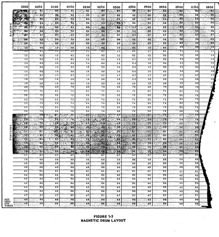
The storage (formerly called "memory") unit of the 650 is a cobalt-nickel-plated cylinder about 4: inches in diameter and 16 inches long called a Magnetic Drum or just Drum. The drum revolves at about 12,500 rpm. Information is stored on the drum in the form of magnetized spots. The drum is divided into 2000 word locations, each word containing 10 digits and a sign. It is convenient to think of the surface of the drum as divided into 2000 rectangles, each containing 10 digits and a sign. Each rectangle is then a "drum location." Figure 1.3 shows a layout of a portion of the drum. Each location is given a "street address" or "drum location address" which is a 4:-digit number running from 0000 to 1999. Words may be thought of as stored in 4:0 bands of 50 words each, running around the drum. Since the drum rotates at
6 • SIMPLE PROGRAMMING
12,500 rpm, the largest possible access time-Le., time to read out one word of information from a specific location-would be .0048 second, with the average time being much less if a sensible programming procedure is followed. A word stored on the drum remains there until another word is stored on top of it, at which time the old word is first automatically canceled by the new word. Words remain on the drum even if the power is cut off.
1-7. ACCUMULATOR.
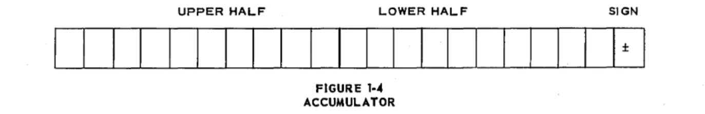
The arithmetical unit is a 20-digit accumulator (like a 20-digit desk calculator). For con-venience, it is thought of as divided into three parts, the upper half of the accumulator (10 digits), the lower half of the accumulator (10 digits), and a sign. In some operations it is
UPPER HALF LOWER HALF SIGN
I I
I I I I I I
I
I I I
I
I
I I
I I I I I
±I
FIGURE 1·'-ACCUMULATOR
desirable to use only the upper half of the accumulator; in some, to use only the lower half; and, in some, to use both parts. However, the machine always behaves as if the entire 20-digit accumulator were used, with zeros usually being placed on the unused section. A result that is in the accumulator will remain" there until it is erased by a "reset" operation, or al-tered by an arithmetical operation, or until the power is shut off. (Capacitor storage which is used in the accumulator does not "hold"-Le., remain indefinitely in the absence of regen-erative power-as" does the magnetic storage of the drum.)
1-8. DISTRIBUTOR.
The distributor has a capacity of one word (10 digits and a sign). Any word transferred between the drum and the accumulator passes through the distributor and remains there until
it is replaoed by another word. A word located in the distributor is available more quickly
IBM CARD
INPUT-OUTPUT
10 DIGITS AND SIGN
FIGURE 1·5
ACCUMULATOR 20 DIGITS AND SIGN
SIMPLE PROGRAMMING. 7
than one on the drum, and should be used when appropriate. A word will remain in the dis-tributor until another word is transferred from the drum to the accumulator, or from the ac-cumulator to the drum, or until the power is shut off.
The schematic diagram in Figure 1.5 will help fix this important "routing pattern" in your mind.
1-9. INSTRUCTIONS.
The IBM 650 is a stored-program machine. The instructions are stored on the drum in the same form as data. Since the only thing which the drum can store is a set of 10-digit signed numbers, the instructions to the machine are coded as 10-digit numbers. The 10 digits of an instruction are sectioned into three groups as shown:
10 9 8 7 6 5
I
I
I I
OP DATA
CODE ADDRESS
In general:
4 3 2
NEXT
INSTRUCTION
ADDRESS
DIGIT POSITION
SIGN GROUP
NAME
OPeration: The two digits on the left (positions 10,9) tell the machine what operation to per-form and where to perper-form it. (Example: 65 means "Reset the entire 20-digit accumulator to zero, and then add the contents of that storage location specified by the data address to the lower half of the accumulator.")
Data Address: The four digits in positions 8-5 (Data Address) usually give the storage loca-tion needed in performing the OPeraloca-tion code of the instrucloca-tion.
Instruction Address: The four right-hand digits (positions 4-1) usually give the storage loca-tion of the next instrucloca-tion,-i.e., tell the machine where to go for its next instrucloca-tion after the 0 Peration has been performed.
Sign: The sign of the instruction (±) is quite useful in connection with subroutines, but will not be discussed until needed. A sign must appear on each instruction in storage, or the machine will stop, but it is of no importance here what sign appears. For the present we shall make them all +. The sign has no effect on the operation code.
1-10. A PROBLEM.
Let us assume that a deck of data cards, data deck 1, contains 600 IBM cards. The first card word (Cols. 1-10) consists of a 10-digit signed number, of which the first three digits are always zero; hence, the first card word contains a 7-digit number, Xi. The second card word (Cols. 11-20) contains a 10-digit word of which the six high-order digits are all zeros; hence, the second word contains a 4-digit number, Yi, with its sign. The other six
words on the card will not be discussed currently, since only the first two words are used in this example.
8 • SIMPLE PROGRAMMING
/0
0
0
0
0
0
0
0
0
WORDI WO~O::z WORD 3 WORD4 WORD 5 WORD6 WORD 7 WORD e
0
0
0
00
0
0
0OOOXXXXXXX OOOOOOyyyy
1 2 3 4 5 6 ' B 9U\l12131415IG17181UOZlrLLJ242526272b29~513233J43536.313l'l9«1"424l~45~,414849:1SJ51,53~';!j5GoI58.9fO"G~&164656""76859lt17171;j747J7&IJ:.7~1/IJ
the reader will almost certainly wish eventually to learn to program using SOAP, we shall adopt these symbols throughout. The main difference between the two codes is that each SOAP operation code contains exactly three letters, while the old code has from two to five letters.
EXAMPLE 1.
Compute the sum Zi
=
Xi + Yi for each of the 600 pairs of Xi' Yi which are given in deck 1, words one and two. How would you explain to someone what you wish him to do, using a desk calculator, if you were giving him this assignment? Roughly, you would probably tell him to read the card and determine Xi and Yi• Next, he should compute Xi + Yi == Zi and mark Zi on a blank card, then go to the next card and repeat the instructions.1. READ A CARD
TO DETERMINE Xi AND Y i
2.
I.
COMPUTE Zi = XI + Y il
3.
I
WRITE Z. ON A BLANK CARD1
'"
4. GO BACK TO STEP
This might be adequate if the person knew how to add on a desk calculator.
A more detailed set of .instructions might be: Read a card for Xi and Yi; clear (reset) the
desk calculator (accumulator) to all zeros; add X i into the accumulator; add Y
i into the
ac-cumulator; read out the answer Zi from the accumulator and remember the answer long enough to write it in the desired columns of a blank card. Repeat these instructions with the next card.
READ A CARD
TO DETERMINE Xi AND Y i ,l.
I
COMPUTE Xi + Y i = ZjI
1
PUNCH Zj ON A BLANK CARD J~---I
SIMPLE PROGRAMMING. 9
When writing a program, in addition to writing down instructions (10-digit words), it is also necessary to keep track of the drum location in which the instruction is stored. A form similar to that which the student has on his IBM 650 Planning Chart (Form 22-6151-2) is used for this. We shall arbitrarily choose to locate our first instruction in drum location 0500 and each successive instruction in a location 10 larger than its predecessor, e.g., 0500, 0510, 0520, 0530 ....
INSTRUCTION
DRUM LOCA TION r- -r-- NEXT
OF INSTRUCTION
INSTRUCTION OPERATION DATA ADDRESS ADDRESS COMMENTS 0500 RCD 70 1851 0510
This first instruction ReD (Read CarD, or, sometimes, RD1-ReaD input one) 70 1851 0510is to be located in drum location 0500. It tells the machine to read a card (8 words, 80 digits) and to store the contents of these 8 words in drum locations 1851, 1852, ..• , 1858; then to go
- -
-to drum location 0510 for its next instruction. Note that both X. and Y. are now on the drum. 1 1 Xi is in location 1851, while Yi is in 1852. Drum locations 185~-1858 also contain data, but they will not be used in this problem. Drum locations 1859, 1860 have zeros stored in them through the board wiring used on the 533-input-output unit. (Caution: Unless an experienced person has wired the board, these zeros may not have a sign with the word. Do not try to use them unless you are certain they also have a sign. The program will stop if a number without a sign is used.)
The next instruction is to Reset (clear) the entire accumulator and Add Xi (now in loca-tion 1851) into the Lower half of the accumulator (Note: The upper half of the accumulator might have been used. The choice was arbitrary.)
INSTRUCTION
DRUM LOCATION -r-
-r-NEXT
OF INSTRUCTION
INSTRUCTION OPERATION DATA ADDRESS ADDRESS COMMENTS
0500 RCD 70 1851 0510
0510 RAL 65 1a51 0520
70 • SIMPLE PROGRAMMING
The program continues:
INSTRUCTION
DRUM LOCATION -r- -r- NEXT
OF INSTRUCTION
INSTRUCTION OPERATION DATA ADDRESS ADDRESS COMMENTS
0500 RCD 70 1851 0510 OS10 RAL 55 18S1 0520 0520 ALO 15 1852 0530
The last instruction (in 0520) tells the machine to Ad~ (without reset) the contents of drum location 1852 (namely, Y) to whatever is in the LOwer accumulator (it contains Xi)' thus form-ing Zi = Xi + Yi there, anA then to go to drum location 0530 for its next instruction.
We now wish to punch out Zi (the contents of the lower accumulator). To do so, it is necessary to store Zi on the drum, since it is impossible to punch directly from the accumu-lator. Furthermore, there are only certain drum locations from which data may be punched. (See shaded portion of Figure 1.3) Quite arbitrarily we select 1530 (one such location) for this purpose. The program now reads:
INSTRUCTION
DRUM LOCATION NEXT
OF INSTRUCTION
INSTRUCTION OPERATION DATA ADDRESS ADDRESS
0500 RCD 70 1851 0510 0510 RAL 65 1851 0520 0520 ALO 15 1852 0530 0530 STL 20 1530 0540
which tells the machine to store the contents of the lower half of the accumulator in drum location 1530 and to go to drum location 0540 for its next instruction. (Note: The number Zi is now in three locations in the 650: in drum location 1530; in the lower accumulator; and, since it just passed from accumulator to drum, it also appears in the distributor.) We now tell the 650 to punch out the contents of drum location 1530 and to go back to location 0500 for its next instruction, which is (ReD) 70 1851 0510-i.e., read another card and store it in drum locations 1851 to 1858, then go to location 0510 for the next instruction.
INSTRUCTION
DRUM LOCATION NEXT
OF INSTRUCTION
INSTRUCTION OPERATION DATA ADDRESS ADDRESS
0500 RCD 70 1851 0510 0510 RAL 55 1851 0520 0520 ALO 15 1852 0530 0530 STL 20 1530 0540 0540 PCH 71 1530 oseo
If this 5-step program is loaded onto the drum by some means (actually this, too, is done through punched cards) and the set of 600 XiYi data cards placed· in the read hopper of the 533-read-punch unit, the machine will read the Xi and Yi from the first card when the program is started, then reset (clear) the lower accumulator and add in Xi; add Yi to form Zi = Xi + Yi;
SIMPLE PROGRAMMING. 77
unit; read the Xi and Yi from next card, etc., etc. When all 600 cards have been processed, the 650 will receive the final instruction 70 1851 0510, but there will be no card to read, so the machine will stop. The total time to read, compute, and punch these 600 cards will be about 6 minutes. However, this is not to be interpreted that it takes the machine 6 minutes to compute and store these 600 sums. Most of the time the computer. is merely sitting idle, wait-ing for the punch unit which has a maximum output capacity of 100 cards per minute. Actually, the 650 could have computed and punched not only Xi + Yi, but also several other functions,
such as Vi
=
X~ - 4XiYi - Xi and Wi=
X~Y~ - 3Xi + Yi - 17, in addition to Zi=
Xi + Yi, in thesame 6-minute period. It makes no difference, in time, whether only one word, Zi' or all eight words of the output card are punched! -It would, of course, require a longer program to com-pute all three, Zi' Vi' and Wi' but the 650 would be able to comcom-pute and punch all of them in the same 6 minutes it would take to compute and punch the Zi'S alone. This may give you a clue as to why you must learn a little about how to program the 650, even if you only plan to use it by having someone else write your programs. Often you can secure much more output information for the same "price" if you plan for it in advance.
If the above program is used, the results will be a series of 600 cards, each of which will contain a Zi in the fourth word (Col. 31-40) of the card, and zeros elsewhere. The output card contains the contents of the eight drum locations 1527-1534 in words 1 to 8 of the card, respectively, if the "standard" 8- to 10-digit word f>33 control board is used. The kth output card will contain the sum of the two numbers on the kth input card.
If someone should happen to drop the answer pack of cards, there would be no way to get them back into order. This is embarrassing and it is also costly. To avoid this difficulty, you, the student, are asked (Problem 3, Set 1-11) to reprogram this problem in such a manner that not only ZI but also ~ and Yi are punched on each output card. Store the Xi in drum loca-tion 1527 and the Y1 in location 1528. Your punch instruction can still be 71 1530 0500, al-though it will be located in a different drum location. Using one of the "standard control boards," which we assume our 533 read-punch unit contains, any data address between 1500 and 1549 used with OP code 71 will cause all eight drum locations 1527 to 1534 to be punched out in words 1 to 8, respectively, of the output card.
1-11. OPERATION CODES.
The operation codes needed in the following problem set are described here.
70 RCD (Read CarD). You may use RD1 in place of RCD: This operation code causes the machine to read the 80 columns of an IBM card into the 10 read words (xxOl to xxl0, or xx51 to xx60; see Fig. 1.3) in the band selected by the Data Address. The xx means any valid number or address-for example, 0001 to 0010 or 1951 to 1960. With the" standard 5 33 board," we are assuming that card-word 1 (Cols. 1-10) becomes the first word in the chosen read section, card-word 2 (Cols. 11-20) becomes the second word in the chosen read section ... card-word 8 (Cols. 71-80) becomes the eighth word (i.e., xx08 or xx58) in the chosen read section and 0000000000 is automatically placed in words 9 and 10. Any-thing previously stored in these read locations is lost when the contents of a new card are read in. It takes 300 milliseconds (.3 second) to read a card into the machine, but of these 300 milliseconds, 270 milliseconds are available for computing as a result of an irigenious read buffer storage discussed in Chapter 2.
12 • SIMPLE PROGRAMMING
1.3) to be punched into an IBM card. Board wiring selects the digits and order in which they are punched. Our' 'standard board" takes the first eight words of the punching section of the drum (xx27 to xx34, or xx77 to xx84) into the eight words of the card, ig-noring the last two words of the punching section.
24 STD (STore Distributor): The word (10 digits and sign) in the distributor is stored into the drum location specified by the Data Address. The word also remains in the distributor. 15 ALO (Add to L Ower): The 10-digit-and-sign word in the location specified by the Data
Address is added to the lower 10 digits of the 20-digit accumulator. The word is found in the distributor, and also in its former location, after the operation is complete.
16 SLO (Subtract from LOwer): The word in the location specified by the Data Address is sub-tracted (algebraic subtraction) from the lower 10 digits of the 20-digit accumulator. The word is, of course, in the distributor and still in its former (drum) location after the operation is complete.
65 RAL (Reset and Add into Lower):IReset (clear) the entire 20-digit accumulator to zero, and add the word specified in the Data Address to the lower 10-digits of the accumulator. The word is on the drum, in the distributor, and in the lower half of the accumulator after the 65 operation is completed.
20 STL (STore Lower onto drum): The lower half of the accumulator (10 digits and sign) is stored into the drum location specified by the Data Address, replacing whatever was al-ready in the drum location. The contents of the lower half of the accumulator are undis-turbed, and the stored word is in the distributor after the operation is complete.
69 LDD (LoaD Distributor): The word in the location specified. in the Data Address is brought into the distributor. It also remains, unchanged, on the drum.
These eight operation codes will enable you to program a number of problems. In doing so, you will not only gain familiarity with 650 technique, but certain properties of the opera-tions themselves will be brought out in the problems. The problems in this manual are de-signed to help you learn how the computer works; and if you are to achieve maximum learning
in the shortest possible time, each problem should be attempted and the results discussed with fellow students before the next class session.
Problem Set 1-11
1. The numbers given with each problem show the contents of the accumulator, distribu-tor, and of a specific drum location, before the instruction is given. Write the contents of each after the command has been executed.
Accumulator
OP Data Upper Lower Distributor Drum Storage Code Address (9003) (0002) (9001) Loc Contents (a) LDD S9 1978 + 0000098765 0000605679 "'70000000099 1978 + 1234500000
(b) STD 24 0030 + 0 456558903 0000000000 -0000089997 0030 +0987999765
(c) RAL 65 1944 - 9999999999 4444444444 + 9999999955 1944 + 9ee9999889
(d) ALO 15 1776 -1111111111 889899999R +098765432 1776 + 55555$5555
(e) SLO 1S 1492 + 1492177622 0000000000 - 9999988875 1492 + 3333333333
SIMPLE PROGRAMMING. 13
Accumulator
OP Data Upper Lower Distributor Drum Storage
Code Address (8003) (8002) (8001) Loc Contents
(g) AL.O 15 0024 + 0000000080 0000000777 + 0006000777 0024 -0000033333
(h) RAL. 65 0945 +9999999999 9999977786 + 0908070706 0945 - 0001213140
(i) STL. 20 1973 -0008800001 5555555555 - 3456723456 1973 + 2345645376
(j) STL. 20 1000 + 0000000000- 0000000043 - 0987223434 1000 + 3333343334
2. (a) Take a 650 Planning Chart (Form 22-6151-2) and write the 5-step program given in Example 1. As you write each step, also note the contents of the upper accumulator, lower
accumulator~ and distributor for the first card which contains Xl = 0005555555 +,
y 1 = 0000003333 +. Assume that after the first operation~ 70 1851 0510, the upper half of
the accumulator contains the digits of your telephone number, the lower half contains the digits of your girl's telephone number with a (+) sign, and that the distributor contains 1492177657 -, all of which are left over from a previous problem. The execution of a Read instruction does not alter the contents of the distributor or accumulator.
(b) Show the contents of the upper accumulator, lower accumulator, and distributor after each step of the program on the second time through, assuming that the second card read
con-tains X2 = 0005769121 +, Y 2 = 0000009342 -. \.
3. Reprogram the problem of Example 1, Section 1-10, so that X i and Y i as well as Z i
will be punched in the output card, as suggested in Section 1-10.
4. Show the contents of the upper accumulator, lower accumulator, and distributor after each step of the program you wrote in Problem 3. Do not use specific numbers, but fill in
known as zeros as zeros, and write OOO+--Xi~' OOOOOO+--Y~, OO+--Xi + Yi~'
etc., to show the general nature of contents as well as the range of digits which it will invol vee For example:
INSTRUCTION
OP DA IA
RAL 65 1851 0510
UPPER ACCUMULATOR 0000000000
LOWER ACCUMULATOR DISTRIBUTOR
Ooo~Xi-~ OOO+--Xj----..
5. Write a program which will use the same input Xi' Yi cards as in Example 1, but which will compute T i = 2 X i - Y i and which will punch X i in word 1, Y i in word 2, and T i in word 6
of the output card.
{
STORE X,Y, T IN PUNCH
6. Fill in the Accumulator and Distributor columns of your planning chart for the program of Problem 5, using the type of notation described in Problem 4.
74 • SIMPLE PROGRAMMING
8. If the Xi'S were 2-place decimals, as in Problem 7, but the Yi's were whole numbers (integers), what directions would you give your key-punch operator so that she could punch the Y i'S in such a form that you could use the program of Problem 3 to obtain the correct
Zi=Xi+YI?
9. Alter the situation in Problem 3 by requiring that additional steps be written into the program so that drum location 1534 will contain the sum of the Z /s from the first card to the present card, in each case. What will appear on the output cards? (Hint: Remember 1534 is
part of the punchout band.)
k
10. In addition to placing
L
Z i in drum location 1534 on the kth card, also alter youria 1
k k
program to compute LXi in location 1532 and
L
Y 1 in location 1533. What will the 7thi=1 1:01
output card contain? What will the 600 th output card contain? What will each accumulator and the distributor contain when the machine stops after the 600th card? What will each con-tain after the power is shut off?
600 600 600
11. Is it possible that any of the sums
L
Zp LXi'L
Yi might contain more than 10i= 1 i= 1 1= 1
digits? Why must this possibility be considered?
12. In Section 1-5 we decided that, for the present, the sign of each instruction should be +. However, no such restriction was placed on the data. Suppose some of the 600 cards in Problems 3 and 5 contain negative valu~s for either X i or Y i ' or both. What, if any, changes
need be made in the programs?
k
13. Reprogram Problem 5 so that
L
T i is also punched on the k th card. Discuss thei= 1
k
possibility that
L
T i might be larger than 10 digits, for some k in the range 1 ~ k ~ 600.i= 1
14. Devise a program which will enable you to number 600 cards consecutively within the numbers placed in the 8th word of the card. This could be combined with another program, if desired.
15. Devise a program which will reproduce the first seyen card words (Col. 1-70) of each card in Data Deck 1 on output cards, and will place a card number k in the 8th word· of the kth card. (Hint: Use LDD-69 and STD-24 to move the words and use the program of Problem 14 to
number the cards.)
1-12. LOGICAL TEST-NZU.
In working Problem 3 of the last set, when did you place the Xi and Y 1 into storage
loca-tions 1527 and 1528? It would be possible to do this after ZI was computed, but both com-puting time a.nd storage locations can be saved by storing a needed word when it is already in the distributor. Although there is no time saving on this particular program (why not?), it is a
SIMPLE PROGRAMMING. 15
INSTRUCTION
DRUM LOCATION NEXT
OF INSTRUCTION
INSTRUCTION OPERATION DATA ADDRESS ADDRESS COMMENTS
0500 RCD 70 1851 0510 {READS 8 WORDS
INTO 1851-58.
0510 RAL 65 1851 0520 Xi IN LOWER.
0520 STD 24 1527 0530 STORE X FOR
PUNCH. 0530 ALO 15 1852 0540 Zi = Xi + Y i
IN LOWER.
0540 STD 24 1528 0501* STORES Y j FOR
PUNCH.
0501 STL 20 1530 0511 * STORES Zj FOR
PUNCH.
0511 PCH 71 1530 0500 PUNCH AND
REPEAT.
*By using 0501 rather than 0550 as the address of our next instruction, the program is kept in the same band on the drum.
Under the conditions of the given problem we were assured that the sum would not exceed a 10-digit number. However, once a program is written, it may be used by others who fail to observe this restriction; perhaps we, ourselves, know that we shall wish later to use the same program to add a series of 10-digit numbers which might have an ll-digit sum. If an ll-digit sum is developed in the lower accumulator, the 11th digit will be found in the low-order posi-tion of the upper half of the accumulator. (The reader should recall that there is, really, only one accumulator, and that it is a 20-digit accumulator. It is merely convenient to speak of its upper half and its lower half as separate entities.) An output card from the above program looks like this:
COL. NO. CARD WORD
OOO+-Xi~
1 10 WORD 1 CORRESPONDING 1527 DRUM LOCATION
000000
~Yi-+ ~ZEROS""'"
11 20 21 30 WORD 2 WORD 3
1528
LAST 10 DIGITS OF
X. + Y.
I I ~ ZEROS l
31 40 41 80
WORD 4 WORD 5 WORD 6 WORD 7 WORD 8
1530
The zeros in word 3 and in words 5 to 8 are the result of having zeroed the drum before load-ing the program. We shall alter the program so that it will test the contents of the upper ac-cumulator, and if it is not all zeros-i.e., if an overflow into the upper accumulator has oc-curred-will punch the contents of the upper accumulator into word 3 of the output card and also punch a special warning by punching a 9 into Column 80 if, and only if, an ll-digit sum was developed.
Operation code 44 NZU (Branch on Nonzero in Upper half of accumulator) is an entirely new type of operation, namely, a logical test. This code performs no ari thmetical operation. Instead, it tests the upper accumulator to see whether or not it is zero. If the upper accumu-lator is nonzero, the machine goes to the drum location given in the data address for its next
instruction-i.e., it branches on nonzero in the upper accumulator. If the upper accumulator
is zero, the machine goes to the drum location of the instruction address for its
next.instruc-tion as usual. Thus,
NZU 44 0621 IF NONZERO
16 • SIMPLE PROGRAMMING
will send the machine to drum location 0621 for its next instruction if the upper is nonzero, and to 0521 if the upper is zero. We may use this in our program as follows:
INSTRUCTION
DRUM LOCATION NEXT
OF INSTRUCTION
INSTRUCTION OPERATION DATA ADDRESS ADDRESS 0500 RCD 70 1851 0510
0510 RAL 65 1851 0520 0520 STD 24 1527 0530
0530 AL015 1852 0540
0540 STD 24 1528 0501 0501 STL 20 1530 0511
0511 NZU 44 0621 0521 (NEW INSTRUCTION) (IF NONZERO (IF ZERO
UPPER) UPPER)
0521 PCH 71 1530 0500
0621 STU 21 1529 0631 (NEW INSTRUCTION)
Let us now suppose that drum location 1998 contains a special code word, say
0000000009, which we wish to have punched into word 8 of each card containing an ll-digit sum. This may be accomplished as follows:
0631 0641
LDD 69 STD 24
1998 1534
0941 0521
If the sum in the accumulator contains 10 or fewer significant digits, the program will proceed as before. If it contains 11 digits, we shall go from drum location 0511 to 0621. The instruc-tion in 0621 places the digits from the upper accumulator into punch storage locainstruc-tion 1529, which contained all zeros in the program. The instructions in 0631 and 0641 place the spe-cial code word which identifies an ll-digit-sum card in punch storage location 1534, before continuing with the old program in location 0521, as before. The instruction in 0521 (e.g., 711530 0500) causes all eight words in 1527-1534 to be punched. Notice that many of the instructions need not be written in any particular sequence. The important thing is that the drum locations and data addresses be correct.
The reader should fill in this program on a 650 planning chart, filling in the accumulator and distributor entries both when a 10-digit and when an ll-digit sum is developed. This is a vital part of this course, the purpose of which is to teach you to think in a pattern com-patible with the machine's operation-a quality which is essential in the successful use of computers. This suggested program oontains a serious blunder. You can find it, if you will fill in a planning chart. If an ll-digit sum is developed, all subsequent outputs will show 11-digit sums and will contain a 9 punch in Col. 80. Why? See if you can discover the source of this difficulty before continuing. Consider what the difficulty is-namely, once an 11-digit sum is developed, an ll-digit sum and a 9 in Col.· 80 appear even when only a 10-digit sum is developed subsequently-and discover why the 650 behaves so. Remember that the 650 does exactly what you tell it to do-no more, and no less. Try your hand at "debugging" this pro-gram before you continue!
SIMPLE PROGRAMMING. 77
EXAMPLE 1:
A flow chart of our proposed program looks like this (It is customary although not essential in a flow chart, to indicate a branch by a long oval and two circles:
R
STORE UPPER IN 1529
AND STORE CODE
WORD IN 1534.
READ A CARD
COMPUTE
X. I + Y. I = Z. I
TEST:
IS UPPER HALF
Zj (LOWER 10 DIGITS)
IN PUNCH BAND
OF ACCUMULATOR ZERO?
STORE ZEROS INTO
WORDS 1529
AND 1534.
The astute reader will be able to suggest other possible programs which will accomplish the desired ends.
LOCATION INSTRUCTION
OF NEXT
INSTRUCTION OPERATION DATA INSTRUCTION COMMENT
ADDRESS ADDRESS
0500 RCD 70 1851 0510 READS CARD INTO
1851-58
0510 RAL 65 1851 0520 X. I NTO LOWER
I
0520 STD 24 1527 0530 STORE Xi IN
PUNCH LOCATION
0530 ALO 15 1852 0540 X. + Y. = Z.
I I I
IN LOWER
0540 STD 24 1528 0501 STORE Y. IN PUNCH
I
0501 STL 20 1530 0511 STORE Z. IN PUNCH
I
0511 NZU 44 0621 0521 BRANCH
(IF NONZERO) (IF ZERO)
0621 STU 21 1529 0631 IF NONZERO UPPER
BRANCH
0631 LDD 69 1998 0641 CODE WORD FROM 1998
0641 STD 24 1534 0502 CODE WORD INTO
PUNCH
0521 LDD 69 1859 0531 IF ZERO UPPER BRANCH
0531 STD 24 1529 0541 STORE ZEROS IN 1529
0541 STD 24 1534 0502 STORE ZEROS IN 1934
78 • SIMPLE PROGRAMMING
Another way to guard against developing an 11-digit sum is available if you perform the operations in the upper half of the accumulator. When an 11-digit number is developed in the upper half of the accumulator, ,an overflow occurs. When it does, the overflow light on the console comes on, indicating that an overflow has taken place. If the overflow switch (also on the console) is set to STOP, the program will stop. There is also a "branch on overflow" operation, 47 BOV, which may be used to reroute the program if an overflow occurs, provided the overflow switch is set in the SENSE position. As usual on branch operations, if the specified condition occurs (here, an overflow), the next instruction executed will be in the location given by the Data Address; otherwise the instruction address is used as usual.
1-13. MUL TIPLICA TION.
The operation mUltiply (19 MPY) is somewhat different in nature from those already dis-cussed. The accumulator is reset and one of the 10-digit factors is placed in the upper
ac-cumulator before the instruction MPY
~
is given. Thelocation of the other 10-digit factor is specified in the Data Address of the instruction
NEXT INSTRUCTION
ADDRESS
I I I
• The 20-digit product stretches across both
the upper and lower halves of the accumulator. If it is known that the product will not con-tain more than 10 significant digits-say, the product of the two 4-digit factors, (OOOOOOxxxx). (OOOOOOyyyy)-then the upper accumulator will contain all zeros, and only the lower accu-mulator is pertinent.
We have already discussed 2000 of the 2004 possible addressable locations of the IBM 650. (What are they?) The other four are the console switches (8000), the distributor (8001), the lower accumulator (8002), and the upper accumulator (8003), each of which is a valid and convenient data address or instruction address for most operations. The 800x series ad-dresses are the most quickly accessible on the 650, and should be used where possible. The 650 will not accept an 800x series address as the data address of a store operation (20,21,22, 23,24); in fact, the machine will stop if an 800x series address is used with a store instruc-tion. Storage of a word in an 800x address may be achieved by using OP codes 60,65,69.
EXAMPLE 1:
In a correlation analysis, 600 pairs of 5-digit integers (Xi' Y i) are available on a set of 600 IBM cards, with the X's in word 3 and the Y's in word 4. Either or both values may be negative.
- 69999 ;£ Xi = OOOOOxxxxx ;£ 69999
- 69999 ;£ Yi = OOOOOyyyyy ;£ 69999.
We wish to compute the necessary results, and punch cards containing the following:
~
x. Y. x~ XIYi x~ - X.Y. Y~ y2_ X.Y. y2_ x2WOR~
1I I I I I I I I
A flow chart follows:
READ A CARD TO
OBTAIN X. AND Y.
I I J.
COMPUTE Xi Yi,
STORI NG X. AND Y.
I I
AND X.Y.
I I
I N PUNCH-OUT BAND
!-COMPUTE X2 AND X2 - XY
AND STORE IN PUNCH-OUT BAND
~
COMPUTE y2 AND y2 - XY AND
STORE IN PUNCH-OUT BAND
~
COMPUTE y2 - X2 AND STORE
IN PUNCH-OUT BAND.
1
r
PUNCHI
SIMPLE PROGRAMMING. 79
WE DROP THE
SUBSCRIPTS HERE,
SINCE NO
CONFUSION
WILL ARISE.
The top of your 650 planning chart should be filled in to indicate that word 3 of input contains a 5-digit Xi to be stored into drum location 0303, while word 4 contains a 5-digit Y
i to be
stored into location 0304. The output words will be:
WORD
MEMORY
ADDRESS
OUTPUT
2
1077 1078
X Y
3 4 5
1080 1081
XY x2 - XY
6
1082
y2
7 8
1083 1084
Y2_XY y2_X2
A possible program follows: The command RAU 60 0303 1010 resets the entire 20-digit ac-cumulator and adds the contents of drum location 0303 to the upper half of the acac-cumulator be-fore going to drum location 1010 for its next instruction.
INSTRUCTION
LOCATION NEXT
OF DATA INSTRUCTION
INSTRUCTION OPERATION ADDRESS ADDRESS COMMENTS
1100 RCD 70 0301 1105 1105 RAU 60 0303 1010
1010 STD 24 1077 1015 STORE X
1015 MPY 19 0304 1020 COMPUTE XY
1020 STD 24 1078 1025 STORE Y
1025 STL 20 1080 1030 STORE XY
1030 RAU 60 0303 1035
1035 MPY 19 8001 1040 COMPUTE x 2
20 • SIMPLE PROGRAMMING
INSTRUCTION
LOCATION NEXT
OF DATA INSTRUCTION
INSTRUCTION OPERATION ADDRESS ADDRESS COMMENTS 1040 STL 20 1079 1045 STORE X2
104S SLO 16 1080 1001 COMPUT~ X2 - XY 1001 STL 20 1081 1006 STORE X - XY 1006 RAU 60 0304 1011
1011 MPY 19 8001 1016 COMPUTE y2 1016 STL 20 1082 1021 STORE y2
1021 SLO 16 1080 1026 COMPUTE y2 - XY 1026 STL 20 1083 1031 STORE y2 - XY 1031 SLO 16 1081 1036 COMPUTE y2 _ X2 1036 STL 20 1084 1041
1041 PCH 71 1077 1100
The reader is expected to fill in the accumulator and distributor columns at each step of the program, as he copies it on to a 650 planning chart. Attention is called to the fact that, if an ll-digit product or a sum were developed, the program would ignore the most significant digit and no one would be the wiser. Unless more is known about the nature of the data~ it is quite possible that any of X2 - XY~ y2 - XYj or y2 - X2 might be ll-digit numbers. (Why?) In the
next problem set the reader is asked to reprogram the problem to take care of this possibility, either by including 44 NZU operations which will stop the 650 by sending it to an invalid ad-dress, if an ll-digi t d ifferenceis developed~ or by using the upper half of the accumulator and overflow stop. (Note: The difference between two 10-digit numbers can be an ll-digit number,
if the terms are opposite in sign.)
1-14. NEW OPERATION CODES •.
10 AUP (Add to UPper): The "lO-digit and sign" word in the location specified by the Data Address is added to the upper half of the 20-digit accumulator. If an overflow occurs, the overflow circuit will be activated. If the overflow switch is set to STOP, the program will stop when an overflow occurs.
11 SUP (Subtract from UPper): Similar to 10, but subtracts.
60 RAU (Reset accumulator and Add to UPper half): Resets the entire 20-digit accumulator to plus zero and adds the contents of the Data Address to the upper 10 digits of the
accumulator.
61 RSU (Reset and Subtract from Upper): Resets the entire 20-digi t accumulator and subtracts the contents of the location given in the Data Address from upper half.
66 RSL (Reset and Subtract from Lower): Similar to 61,but subtracts from the lower half. 21 STU (STore Upper): Causes the upper half of the accumulator, with sign of the accumulator,
to be stored in the drum location specified by the Data Address. The contents of the accumulator are unaffected by the operation. The word also appears in the distributor, of course.
44 NZU (Branch on NonZero in Upper): If the upper half of the accumulator contains all zeros, the next instruction to be performed will be found in the Instruction Address. If the upper half is nonzero, the address of the next instruction performed will be found in the Data Address. This operation does not affect the arithmetical units nor the storage units of the 650, but provides a logical test by means of which different branches of a program may be selected.
45 NZ E (Branch on NonZero Entire accumulator): Similar to 44, but the entire 20-digit accumu-lator is examined.
SIMPLE PROGRAMMING. 21
47 BOV (Branch on OVerflow): When the overflow switch on the console is set to SENSE, the program will branch to the location specified in the Data Address if an overflow occurs, but use the Instruction Address as usual if no overflow is present. If the console switch is set to STOP j the program will stop on overflow. (Note': If the console switch is in the
sense position and an overflow occurs, but the BOV is not used, the overflow light will come on, but the 650 will continue to run ignoring the fact that an overflow occurred. Al-ways leave the overflow switch in the STOP position unless you are using the BOV OPeration code.)
00 NO P (No OPeration): The 650 merely goes to the Instruction Address for its next instruc-tion. This code is useful for switching the path of the program if an instruction must be deleted or added. Some valid Data Address (usually 0000) must be included in the Data Address location or the machine will stop.
01 Hl T (Hal T or Stop): If the console programmed stop switch is set to STOP, the 650 will
stop at this operation. If the switch is set to RUN, the 01 code is treated as a NO OPer-tion (00) code. This is useful in debugging programs and will be discussed in greater de-tail later.
1-15. FLOW CHARTS.
The flow chart or block diagram is the heart of all true programming-be it for the 650 or for another computer. No program of any complexity should even be discussed, let alone pro-grammed, without a careful flow chart. A flow chart should show the exact sequence of oper-ations including each branch and its alternatives. It should also indicate how and when loops are tested. A flow chart does not show individual steps used in computing. The object of a flow chart is to present the overall method of attack, without details. There is little or no mention of specific 650 operation in a flow chart. A competent coder can take a flow chart and translate it into a program for an IBM 650j or for a DATATRONj or for one of the IBM 700 series, or almost any other computer. Flow charting is often used to explain processes which do not involve any computer.
The bit of whimsey on the following page which has been making the rounds of computer laboratories for several years may illustrate the point. It purports to be a program for getting to 8 o'clock class.
It would be hard to overemphasize the importance of flow charts. Indeed, the time may come when you will make only the flow chart, leaving the details of programming to someone (or something) else. "For transit" is an example of a "something."
Problem Set 1-15
1. Copy the program given at the end of Section 1-12 on a planning chart, filling in the accumulator and distributor columns.
2. Reprogram Example 1, Section 1-12, using the upper accumulator so that, if an overflow occurs, the program will stop.
3. Explain what the 650 will do upon receipt of each of the following instructions (beware of booby traps). At the beginning of each of the operations, the following situation prevails:
8003 3333333333
8002
2222222222 +
8001
1111111111-(a) RAU 60 a001 XXXX (d) LOO 69 a003 XXXX
(b) SLO 16 8002 XXXX (e) PCH 71 a002 XXXX
(c) STU 21 a001 XXXX (f) SLO 16 a003 xxxx
22 • SIMPLE PROGRAMMING
GIVE HER
$10.00
TURN OFF AL.ARM
GROAN
SHAKE WIFE
CRAWL. OUT
BATHROOM CHORES
BREAKFAST
KISS WIFE
KISS WIFE
RESOL.VE TO SET AL.ARM
EARLIER
WAL.K OUT TO CAR
DRIVE TO CL.ASS
GO BACK FOR THEM
4. Explain the effect of each of the following operations on the entire accumulator which, at the beginning of the operation, contains 20 nonzero digits and a plus sign.
(a) sUP 11 8003 XXXX (b) RAU 60 8003 XXXX
(c) SLO 16 8003 XXXX
(d) RAL 65 8002 XXXX
(e) SUP 11 8002 XXXX (f) RAU 60 8002 XXXX
5. The following programs are intended to form a product of two 3-digit factors located in
SIMPLE PROGRAMMING. 23
(0) LOCATION (b) LOCATION
OF OF
INSTRUCTION OP DA IA INSTRUCTION OP DA IA 0500 RAU 60 0733 0505 0328 RAU 60 0734 0338 0505 MPY 19 0734 0510 0338 MPY 19 0733 0337 0510 STU 21 0727 0515 0337 NZU 44 0300 0345 0515 PCH 71 0730 XXXX 0345 STU 21 0727 0301 0345 PCH 71 0715 0300
6. With the Xi' Yi from the set of 600 cards having X = OOOOOOxxxx in word one, -and Y =
OOOOOOyyyy in word two, make up a flow chart and program which will accomplish the following:
Form the necessary computations to compute and punch output cards of the following form for each input card giving X and Y.
~O:D
1
Y 2X - Y 2x2 - XY 2X3 - X2y + X t - - ZEROS ~WORD 2 WORD 3 WORD 4 WORD 5 WORDS 6, 7, 8
7. Modify your program of Problem 6 before reading the next card, so that it will also punch a digit 9 in Col. 80 if 2X a - X 2y + X is positive.
8. Make up a segment of a program which will accomplish the following:
Obtain A-B in the lower accumulator where A was stored in 0576 and B in 1576. If
A-B
<
0, go to an instruction located in 1426; if A-B = 0, go to an instruction in 1626; and ifA-B > 0, go to an instruction in 1926. (Hint: Use both 45 NZE and 46 EM! operation codes.) 9. Write a flow-chart and a program which will use the 600 cards of Problem 6, and give the following on the output card:
(a) Punch X in word 1 and Y in word 2. (b) If X2
<
XY, punch the difference X2- XY in word 4. (c) If X 2 = XY, punch an 8 in Column 80.
(d) If X 2 > XY, punch a 9 in Column 80 and punch the difference X 2 - XY in word 5. Be sure to include the necessary housekeeping to erase unwanted previous results from the punch band on the drum if nothing is stored there later.
(CHAPTER
21
2-1. READ AND PUNCH.
11[H]~ ®~@
~@[M~@[L~
Before continuing with our discussion of the IBM 650, it is essential that you learn more of how it works. This will greatly improve your programming ability as well as assisting you immeasurably in discovering flaws in your program.
You already know that the code 70 ReD causes the contents of an input card to be read into the 650, and that it reads the entire card (80 digits) into either xxOl xxl0 or xx·51 -xx60 locations. We have assumed that ,the 80 columns of the card were read into the first 8 words of the read strip on the drum, and that zeros were fed into the other locations. Although this may be done, it is not necessary, since control-panel wiring in the 533 read-punch unit can be used to place any digit desired in any given position in the 100 (10 words) available drum digits and any sign desired in any of the 10 available sign positions of these words. This data may be taken from the input cards, or may consist of constants supplied by the 533 unit. The control panel may even be so wired that the location of a High Punch (+ or 12 punch) iIi certain columns will change the entire arrangement in which data are fed into the drum. The wiring of these boards is a separate study, and need not concern us at present, except that even nonprogramming users of the 650 must realize that the input is quite
versatile! Similar remarks apply to the output. This is especially important in business data processing such as inventory, accounting, payroll applications, etc. Students interested in these fields should study board wiring.
The 650 has an input rate of 200 cards per minute, but this does not mean that the ma-chine is unable to c