2020 4th International Conference on Modelling, Simulation and Applied Mathematics (MSAM 2020) ISBN: 978-1-60595-674-9
Mission Reliability Modeling and Prediction of an Automatic
Sprinkler System
Xiao YU, Jian-Jun QI*, Li-Qin WANG and Dong-Feng WANG
Beijing Special Engineering Design and Research Institute, Beijing 100028, China
*Corresponding author
Keywords: Sprinkler System, Mission reliability, Reliability modeling, Maintenance strategy.
Abstract. If the sprinkler system cannot be started at the time of need, it may cause huge economic losses. The system needs to have high reliability. Therefore, in the design stage of sprinkler system, it is necessary to carry out reliability modeling and prediction to ensure that the system reliability can meet the requirements. In this paper, the design scheme of a building sprinkler system is analyzed in depth, and then a task reliability model considering maintenance strategy, stand-by period failure and task period failure is established, and the reliability is predicted to evaluate whether the design scheme of the system can meet the design needs.
Introduction
Automatic sprinkler system is an essential part of industrial buildings, its main task is to spray after the fire, to protect equipment and prevent the spread of fire. The occurrence of fire is a small probability event. If there is no fire, the failure of sprinkler system is not important. When a fire occurs, the system needs to be able to start normally and continue to work until the task is completed. Therefore, in the design of the sprinkler system, it is necessary to start from the requirements of the fire protection task of the building and predict the task reliability of the system. Only in this way, it can be sure that that the mission reliability of the system can meet the actual needs.
For systems with high reliability requirements, reliability modeling and prediction work should be carried out in the design phase to ensure that the reliability of the system can meet the actual needs[1,2]. Researchers have been committed to improving the safety and reliability of the fire protection system design scheme, but lack of systematic research results on how to build a reliability model and predict the system reliability according to the characteristics of the fire protection system[3-5].
In this paper, the working principle of the sprinkler system is first analyzed. Secondly, the task reliability model is established. Thirdly, the calculation example is given. Finally, the paper is summarized.
Design Scheme Analysis of Automatic Sprinkler System
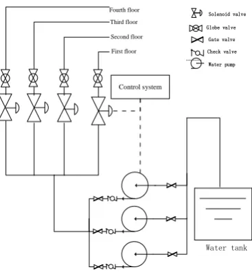
Water tank
Control system
Gate valve Check valve
Fourth floor Third floor Second floor First floor
Globe valve Solenoid valve
[image:2.595.208.392.78.276.2]Water pump
Figure 1. Design scheme of automatic sprinkler system.
Under normal conditions, the water tank is full of water to ensure that the automatic sprinkler system can spray for 40 to 60 minutes continuously. The water pump is a plunger pump, which is not working during the standby period. After being electrified, the water in the water tank can be drawn into the water pipe to increase the water pressure in the water pipe and supply water to the pipe. Under normal conditions, two water pumps are started and the third one is standby. After the check valve is powered on, the pressure at the water inlet end is high, which forces the valve to open. The check valve corresponding to the standby water pump is in the closed state and plays the role of backflow check. Leakage of the check valve corresponding to the standby water pump will cause backflow of water, resulting in insufficient water supply of the pipe network. In this case, it is necessary to turn the standby pump into the working pump, and turn off the working pump with the corresponding check valve in good condition to become the standby pump.
The gate valve remains open during the standby period. When the water pump system needs maintenance, the gate valves at both ends are closed. The globe valve is similar to the gate valve in that it is used to close the pipeline when repairing the pipeline. The solenoid valve belongs to the pneumatic solenoid valve, which is closed during standby period. When receiving the command from the control system, the valve opens, so that the pipeline is smooth. Since the four floors are respectively four enclosed spaces, the four water spray pipe networks are controlled by different solenoid valves. There are 14 shower nozzles on each floor. As long as 12 of them can work normally, they can play the role of protection equipment.
System Reliability Modeling
Failure Mode Analysis
The sprinkler system is on standby for a long time. When there is a fire, it needs to work continuously for a period of time until the task is completed. During the standby period, the system will be detected regularly. Once the equipment fault is found, it can be repaired immediately. During the mission, the system is non repairable. As shown in Figure 2, it is assumed that the detection cycle of the system is
𝑎, the time from the time of fire occurrence to the last maintenance is 𝑥, and the time of fire control mission is 𝑡.
The time x from the last detection to now
Mission tiem t
[image:2.595.193.403.721.772.2]From Figure 2, it can be seen that there are two main types of system faults that affect the success of tasks, one is standby period fault and the other is mission period fault.
(1) Failure During Standby Period. Water pump, solenoid valve and other equipment will be affected by aging, corrosion and other factors during standby period, resulting in failure. Only regular maintenance can discover the equipment failure and repair or replace the failed parts.
(2) Failure During Working Period. The time of fire control mission is very short, which can be ignored compared with standby time, but the failure rate in working period is generally significantly higher than that in standby period.
According to the above analysis and the failure rate data of various equipment in the reliability database, the following conclusions can be drawn:
(1) The state of solenoid valve and water pump during standby and operation is quite different, and the failure rate is quite different, so it is necessary to distinguish the standby period and working period separately. When calculating mission reliability, it is necessary to calculate the reliability of standby period and working period respectively.
(2) The environment of slow closing check valve during standby and working time is similar. Both ends maintain a certain water pressure, and the failure rate difference is not large, so it is not necessary to separate the failure rate of check valve. Compared with the standby time, the working time can be ignored, so when considering the task reliability of the whole system, the failure of check valve during the fire task is ignored.
(3) The failure of gate valve and ball valve does not affect the fire control mission of high-pressure water mist subsystem, and does not participate in the task reliability modeling of the system.
(4) During the working period, the spray effect of the spray nozzle may be poor due to the failure, but this will not affect the overall spray intensity, that is, it will not affect the completion of the task, and it is not necessary to analyze the failure during the working period.
(5) The subsystem composed of water pump and check valve system has two kinds of failure possibilities. The first is the failure of two or more water pumps. When two water pumps fail, the water in the pipeline is insufficient, and the spraying intensity is not enough. The second is the failure of a certain water pump, and the check valve connected with it also fails. In this case, the failed water pump does not work, and the water in the pipeline is recycled. The water pressure in the fire pipe network is reduced and the spraying intensity is not enough.
Mission Reliability Modeling
The mission reliability of the sprinkler system is affected by the maintenance strategy, the time of fire occurrence and the reliability level of the system itself. There are differences in mission reliability corresponding to fire at different times under different maintenance measurements. Therefore, the expected value of mission reliability can be taken as the final evaluation result of mission reliability. The specific calculation formula is as follows:
𝑅̄ = ∫ 𝑓(𝑎)𝑅(𝑥)𝑑𝑥0𝑎 (1)
In the above formula, 𝑅̄ denotes the expected value of mission reliability. 𝑎 denotes the interval time of regular detection. 𝑓(𝑎) denotes the probability density function of fire occurrence. 𝑥 represents the interval time between fire occurrence and last detection. 𝑅(𝑥) represents the reliability of the system that can start and complete the task after fire occurrence.
The occurrence of fire is unpredictable and may occur at any time, so it can be assumed that it follows the average distribution. Since the fire control equipment is always maintained once according to interval 𝒂 during the standby period, the fire must occur in the interval between one detection time and the next detection time. Therefore, the probability density function of fire occurrence can be obtained as follows:
The calculation of 𝑅(𝑥) needs to consider the failure of the system during the standby period and the failure during working time. According to the design scheme of the system, the mission reliability diagram of the system can be drawn as shown in Figure 3:
Control subsystem
Water pump and check valve
subsystem
Solenoid valve subsystem
[image:4.595.98.493.122.160.2]Shower nozzle subsystem
Figure 3. Reliability diagram of the system.
As shown in Figure 3, if any subsystem fails during standby or working time, the fire control mission will fail. The subsystems are connected in series, 𝑅(𝑥) can be calculated by the following formula:
𝑅(𝑥) = 𝑅𝑐(𝑥)𝑅𝑤(𝑥)𝑅𝑠𝑜(𝑥)𝑅𝑠ℎ(𝑥) (3)
In the above formula, 𝑅𝑐(𝑥), 𝑅𝑤(𝑥), 𝑅𝑠𝑜(𝑥) and 𝑅𝑠ℎ(𝑥) respectively represent the subsystem
reliability of control, water pump and check valve, solenoid valve and spray nozzle. Therefore, it is necessary to calculate the reliability for the above four subsystems to complete the standby mission and fire control mission at the same time.
(1) Control Subsystem. The control subsystem is in power on state for a long time. The failure rate during standby is similar to that during working time. As the task time is far less than the standby time, the failure of the control subsystem during the task can be ignored. Therefore, the reliability calculation formula of the control subsystem is as follows:
𝑅𝑐(𝑥)=e-x𝜆𝑐 (4) In the above formula, 𝜆𝑐 denotes the failure rate of the control subsystem.
(2) Solenoid Valve Subsystem. The solenoid valve subsystem consists of four solenoid valves, which control the fire pipe network of different floors respectively. The reliability of the fire control mission of the solenoid valve is not only related to the time x from the time of fire occurrence to the last detection, but also related to the time 𝑡 of the fire control mission. According to the requirements of the design scheme, 𝑡 is regarded as a constant in this paper. Since the four solenoid valves are the same, the failure rate during standby time is 𝜆𝑠𝑜1, and the failure rate during working time is 𝜆𝑠𝑜1. The failure rate of the solenoid valve in the working period is much higher than that in the standby period, as a result, both kinds of failure should be considered. Therefore:
𝑅𝑠𝑜 = 𝑒−𝜆𝑠𝑜1𝑥× 𝑒−𝜆𝑠𝑜2𝑡 (5) (3) Shower Nozzle Subsystem. There are 14 shower nozzles on each floor, which are independent of each other. The failure of one shower nozzle will not affect the work of other spray heads. The system can be seen as a K (k = 12) system from n (n = 14). The failure rate of each spray nozzle during standby period is recorded as 𝜆𝑠ℎ. As the failure does not affect the normal spray during the working time, the failure during the working can be ignored in the calculation of the reliability of the shower nozzle system. Therefore:
𝑅𝑠ℎ=e-14×𝜆𝑠ℎ𝑥
+C14
1 𝑒-13×𝜆𝑠ℎ𝑚(
1-e−𝜆𝑠ℎ𝑥)+C14
2 𝑒-12×𝜆𝑠ℎ𝑥(
1-e-2×𝜆𝑠ℎ𝑥) (6)
(4) Water Pump and Check Value Subsystem. The water pump and check value subsystem is composed of three water pumps and three check valves. Two pumps are required to work continuously in the process of fire control, and the check valve corresponding to the standby pump can play a role of backflow check. There are two failure modes of water pump: failure may be caused by aging and corrosion during standby time; failure may be caused by fatigue and damage during the working time. Suppose that the failure rates of the two cases are 𝜆𝑝1 and 𝜆𝑝2 respectively, and the failure rates of the check valve in the working state and in the standby period are basically the same as
𝑃𝑝1 = 𝑒−𝜆𝑝1𝑥 (7)
The probability that a single pump will not fail during the working time is:
𝑃𝑝2 = 𝑒−𝜆𝑝2𝑡 (8) The probability that a single valve can work normally is:
𝑃𝑔 = 𝑒−𝜆𝑔𝑥 (9)
As the probability of failure of check valve during mission time can be ignored, there are five cases that the water pump and check value subsystem can finish the fire control mission:
Case 1: Water Pump and Valve are Normal Before Fire. There are two possible situations in the process of the task: one is that the two pumps start normally and work until the fire fighting task is completed, and the standby pump is always on standby, so the fire fighting task can be completed without starting; the other is that the two pumps start normally but one of them fails in the process of work, and the standby pump starts until the mission is completed.
The probability of the first kind of situation:
𝑃11 = 𝑃𝑝13 𝑃
𝑔3𝑃𝑝22 (10)
The probability of the second kind of situation:
𝑃12 = 𝑃𝑝13 𝑃
𝑔3𝑃𝑝2𝐶21∫ 𝜆0𝑡 𝑝2𝑒−𝜆𝑝2𝑥𝑒−𝜆𝑝2(𝑡−𝑥)𝑑𝑥 = 𝑃𝑝13 𝑃𝑔3𝑃𝑝2𝑃𝑝2𝐶21𝜆𝑝2𝑡𝑒−𝜆𝑝2𝑡 (11)
As a result, the probability of case 1 is that:
𝑃1 = 𝑃11+ 𝑃12 (12)
Case 2: Three Water Pumps can Work Before the Fire, and Two Valves are Normal. The fault valve can be any one of the three valves, and the corresponding water pump can only be used as a working pump until the task is completed. There are two situations. The first one is that the standby pump does not need to start to complete the fire control mission. The other one is that the standby pump starts instead of the failure pump until the mission finished.
The probability of the first situation is:
𝑃21 = 𝑃𝑝13 𝑃
𝑝22 𝐶31𝑃𝑔2× (1 − 𝑃𝑔) (13)
The probability of the second situation is:
𝑃21 = 𝑃𝑝13 𝐶31𝑃𝑔2× (1 − 𝑃𝑔) ∫ 𝜆0𝑡 𝑝2𝑒−𝜆𝑝2𝑥𝑒−𝜆𝑝2(t-𝑥)𝑑𝑥 = 𝐶31𝑃𝑝13 𝑃𝑔2𝜆𝑝2te−𝜆𝑝2𝑡× (1 − 𝑃𝑔) (14)
As a result, the probability of case 2 is that:
𝑃2 = 𝑃21+ 𝑃22 (15) Case 3: Two Pumps and Three Valves were Normal Before the Fire. There is no standby pump, and the two pumps continue to work until the fire control mission is completed. The probability is that:
𝑃3=C32𝑃
𝑝12 𝑃𝑔3𝑃𝑝22 × (1 − 𝑃𝑔) (16) Case 4: Two Water Pumps and Two Valves are Normal Before the Fire. The fault valve can be any one, the corresponding water pump can be any one of the two working pumps, the fault water pump corresponding to the check valve that can work normally, the two working pumps can work normally until the task is completed. Its probability is:
𝑃4=C31𝐶
Case 5: Three Pumps and One Valve Were Normal Before the Fire. The two faulty valves are any two of the three valves, and the corresponding pumps are all working pumps, which can complete the work normally. Its probability is:
𝑃5=C31𝑃
𝑝12 𝑃𝑝22 (1 − 𝑃𝑝1)(1-𝑃𝑔)2 (18)
Considering the five cases above, the reliability of the water pump and check value subsystem is:
𝑅𝑤(𝑥) = 𝑃1+ 𝑃2+ 𝑃3+ 𝑃4+ 𝑃5 (19)
According to the above calculation process, the mission reliability of sprinkler system can be calculated finally.
Example
The basic reliability data obtained by querying the reliability database of non electronic products are shown in the following table:
Table 1. Equipment failure rate data.
Equipment Mission phase Failure rate (per million hours)
Solenoid valve Standby 0.019
Working 10.150
Water pump Standby 0.581
Working 1234.727
Check valve Standby 5.926
Shower nozzle Standby 0.0085
Control subsystem Standby 5.7897
According to the design requirements, the task working time of the sprinkler system design is 30 minutes. The fire task reliability of the system is related to the standby time and maintenance strategy, so the average task reliability of the system under different maintenance measurements can be calculated by using formula (1). The predicted results of reliability under different maintenance intervals are shown in the table below.
Table 2. Mission reliability prediction results of the system under different detection strategy.
Detection cycle One week 1 month 2 months 3 months 4 months 6 months 12 moths
Reliability 0.9994 0.9978 0.9957 0.9935 0.9913 0.987 0.9736
According to the management requirements of facilities and equipment, the sprinkler system is generally detected once a month, and the corresponding average task reliability is 0.9978. As the system reliability requirement is 0.99, the design scheme of the system can meet the actual needs.
Conclusion
Although the automatic sprinkler system is always on standby, it may cause huge economic losses if it cannot successfully complete the fire control mission when it needs to be started. Therefore, in the process of designing the systems, it is necessary to establish reliability model and predict the reliability to ensure that the design scheme of the system can meet the reliability requirements.
Reference
[1] Andre Kleyner, Vitali Volovoi. Application of Petri nets to reliability prediction of occupant safety systems with partial detection and repair[J]. Reliability Engineering & System Safety, 95(6):606-613.
[2] Lindquist, T.M, Bertling, L, Eriksson, R. Circuit breaker failure data and reliability modelling[J]. Iet Generation Transmission & Distribution, 2(6):813-0.
[3] Yanli Zhang, Hongzhang Jin, Jinhuan Zhang. Application of set pair analysis in cascading failure of ship fire-fighting system[C]//Mechatronics and Automation (ICMA), 2012 International Conference on. IEEE, 2012.
[4] Jiang, Hua, Luo, Min Zhou, Li, Lu. Development of a New High-Rise Building Fire Fighting Robot[J]. Advanced Materials Research, 694-697:1711-1716.