© 2016, IRJET | Impact Factor value: 4.45 | ISO 9001:2008 Certified Journal | Page 896
Improving of Energy Efficiency in LTE based MIMO-OFDM systems with
Multiuser rate
K.S. Sreekanth
1, V.P. Kavitha
21
Student, Department ECE, Velammal Engineering College, Chennai, Tamilnadu, India.
2Assistant Professor, Department ECE, Velammal Engineering College, Chennai, Tamilnadu, India.
---***---Abstract -
In today’s world energy efficiency in wirelesscommunication becomes an important topic and also to make eco-friendly environment we need green communication in Telecommunication industry. Moreover, the data traffic is also more among users. So we have to consider both energy efficient and Qos for users. In our project, energy-efficient resource allocation for Long Term Evolution (LTE) cellular mobile systems is implemented. For applying in LTE systems Both Multiple-In Multiple-Out (MIMO), Orthogonal Frequency Division Multiple Access (OFDMA) Radio access network are considered in this work. Function as distinguishing characteristics for LTE resource allocation. In this technique, user requirements are satisfied. We are using Traffic based Resource and Energy Allocation algorithm. Simulation results show that our proposed algorithm improves energy efficiency significantly but also satisfy user’s requirements in high data traffic as well out of all the existing schemes.
Key Words: MIMO, CO2 Emission, Energy Efficiency,
Resource allocation, LTE, OFDMA
1.INTRODUCTION
It is well known that there is unmanageable growth of users in Tele-communication industry. So user’s requirements become high for ubiquitous access, high data rate. Therefore, energy consumption in wireless communication has been increasing. As a result, CO2 is emitted and makes atmosphere polluted [1-2]. and become an obstacle in development of wireless communication. According to Survey, ITU has submitted that the ICT industry produces 2% - 2.5% of total greenhouse gas emission [3-4] That includes PC 40%, data centers 23%, telecommunication 24% and printers 6%. So, out of all we are concentrating on telecommunication to reduce emission of CO2. So to overcome this emission in telecommunication, energy efficient has become a global trend in future wireless telecommunication networks.
The Third Generation Partition Program (3GPP) Long Term Evolution (LTE) is the most advanced technique for next generation cellular systems. To satisfy user we need
to provide high speed data, significant spectral efficiency etc. To do this high amount of energy is used hence 3GPP has integrated Green communication in LTE standards [5].
The base paper [11] explains the energy efficiency in LTE systems by using MIMO, OFDMA, Resource Block (RB) and Sub-Channel assignment are used. In this scheme for individual user they have allocated each RB by Appling resource allocation algorithm. Hence there is a limited use of RB to the user where it can sustain at less number of user i.e. in low traffic load cases it gives an energy efficiency and good QoS where’s in High load case no QoS and energy efficiency is present. In future wireless telecommunication industry, the will be huge development of Mobile user (MU). So we need energy efficient algorithm in the LTE network.
© 2016, IRJET | Impact Factor value: 4.45 | ISO 9001:2008 Certified Journal | Page 897 efficient transmission at Base station and many more
schemes has been studied. Out of all none of the schemes has no algorithm has been satisfying Energy efficient in Base station and also QoS to the users. Hence this motivated me to do the project on energy efficiency in LTE networks using MIMO OFDMA. In this paper, our aim is to minimize the energy consumption in Base Station (BS) transceiver with the help of Multiple-In Multiple-Out - Orthogonal frequency division multiple access systems based on multiple Carrier component (CC) and also certain Quality of Services (QOS) in LTE system.
2. PROBLEM EXPLANATION
2.1 Node Diagram and explanation
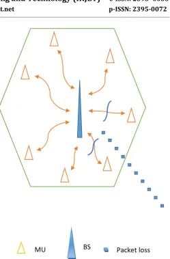
[image:2.595.311.561.58.438.2]The fig. 1 show the LTE cell 4G with MIMO-OFDM systems with Base Station where the Mobile user (MU) are connecting the Base station (BS). This shows that If the less number of MU is present near the base station users can able to connect it easily to the BS. So that MU can get more bandwidth, due to that user can get a high speed data and also get QoS like performance, energy efficiency. If more number of user are connecting the BS at same time there will be packet loss due to high traffic, so that bandwidth will be low and QoS is also poor to the user.
Fig -1: LTE Cell
Fig -2: packet loss in LTE network
The fig. 2 shows that more number of users are connecting the BS, due to that there is a loss of data packet to the user. At the same time the connectivity of the user will be less. So the user won’t get the QoS and there will be more usage of energy at the BS transmission side. Hence to overcome this problem we have proposed Traffic Based Resource and energy Allocation Algorithm.
3. SYSTEM MODEL
3.1 General
Compared to downlink transmission with uplink transmission the load is more at downlink load. Hence we have considered a cellular network for downlink transmission. In this model Traffic Based Resource and energy Allocation Algorithm and Two Component Carrier (CC) that is Primary component carrier (PCC) and Secondary component carrier (SCC) has been used by the Base station at the same time. So we are implementing this concept in Base station. In this PCC is taken for consideration at foremost than SCC. When PCC is found busy, SCC will be activated.
MU
BS
BS
[image:2.595.40.277.397.713.2]© 2016, IRJET | Impact Factor value: 4.45 | ISO 9001:2008 Certified Journal | Page 898
3.2 MIMO-OFDM System
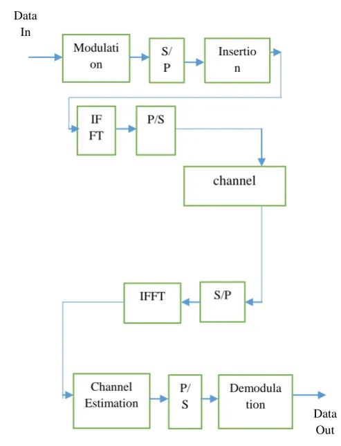
[image:3.595.304.567.121.319.2]MIMO system consider the component of spatial diversity by using spatially separated antennas in a hardened multipath fading environment to produce diversity gain. Advanced techniques in MIMO derive a significant increase in performance for OFDM systems. A reduced block diagram of an OFDM systems is shown in the Fig. 3. [16] Incoming data signal is outlined into some modulation technique such as QAM. The data symbols are identified with the channel information and transmitted signal is restored after all the process.
Fig -3: OFDM Block Diagram
Fig. 4 shows a MIMO-OFDM system with transmitting, and receiving antenna. The incoming signals is outlined into a number of data streams via some modulation technique such as QAM [13]. A block of NS data is encoded into a matrix form and send through the antennas in OFDM blocks. Each OFDM blocks has N sub channels. Cj will be transmitted from the transmit antenna in the OFDM block and pass through the MIMO channel and the same signal will be sent back to OFDM block and to the decoder.
Fig -4: MIMO-OFDM Block diagram
3.4 BLOCK DIAGRAM WITH EXPLANATION
As mentioned above in MIMO-OFDM systems the signal will pass through that channel and it reaches the classifier. The fig. 5 shows the overall block diagram. Classifier help to find whether the input signal is Real time or Non-real time session. The signal is sent to a separate Queue according to First in first out (FIFO) and then identified signal is sent to the admission call control mechanism. At admission call control mechanism there is a process to check the incoming signal and also used to identify the session is to be block in the queue or not. It only identifies the correct Carrier Component (CC) when the user incoming session allowed in the network.
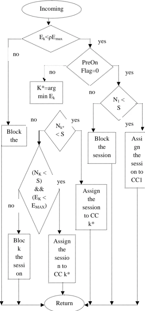
The Fig. 6 shows that When the new incoming session arrives it will check whether the Energies of the Kth carrier (EK) is less than the upper marginal factor of maximum energy available in individual sub frame (ρEMax). If it is yes SCC will check the status can be used or else, it will return and the session is blocked. Here PreOnFlag is used as an indicator and used to determine whether the new user can access SCC. If it is 0 PCC can be used, when the number of session (N) is less than that of Total number of session (S) present. If it is 1 SCC can be used when number of session (N) is greater than the total number of session (S). In both the cases it will check and assign or else the session is blocked and it will re-check. When the session is blocked it will again check the number of session is less than the total number of session and also energy of the carrier should be less than that of upper marginal factor of maximum energy
Data In
Modulati on
S/ P
Insertio n
IF FT
P/S
Demodula tion P/
S
IFFT S/P
Channel Estimation
Data Out
channel
Codi ng
Deco ding OFD
M modul
ation
OFD M Modu lation
OFDM Demod ulation
[image:3.595.42.289.281.604.2]© 2016, IRJET | Impact Factor value: 4.45 | ISO 9001:2008 Certified Journal | Page 899 available in individual sub frame ((NK<S)&&(EK<EMAX)). After
[image:4.595.325.558.196.694.2]this step it will assign to any one of the CC. the result of call admission control mechanism is given to the next block as an input [14]. Next comes the packet scheduler. It is responsible for the packets based on transmission priority and rate of each user. It verifies the packets with the OFDM and data system. In emergency condition, RT packet is set to top priority [18].
Fig -5: System block diagram
Emergency condition = waiting time of a packet in a
queue
Delay of packet constraint.
Next comes the packet scheduler, the scheduler is used to control the number of users and regulate the amount of resource allocated to the user’s due amount of resource is large and also user gets the bad channel condition in a frame. In packet scheduler there is a process in the queue. At first stage, the number of Auxiliary Unit (AU) is estimated by the scheduler. The high priority goes to the user waiting time of
[image:4.595.38.290.239.568.2]head of the line pack is nearer to the delay constraints. The AU required is given volume of urgent date by high transmission rate of the user per AU. In second stage, the packet which is not urgent by the user of Real and Non real time. The user whose channel quality is better in the traffic will be given high priority. At stage 3, the remaining AU are allocated to the user who need more than the AU restriction.
Fig -6: Flow chart of call admission control mechanism
Signal
In
Packet Scheduler Classifiers
P C C Resource
& Energy allocation algorithm
MO-OFDM
S C C Call
Admission control
MI-OFDM
Signal
Out
Assign the sessio
n to CC k* Incoming
session
Ek<ρEmax
PreOn Flag=0
N1 <
S
Nk*
< S
(NK <
S) && (EK <
EMAX)
K*=arg
min Ek
Assi gn the sessi on to
CC1 Block
the session
Assign the session
to CC k*
Bloc k the sessi on Block the sessio
n
Return no
yes
no
no
no no
yes yes yes
© 2016, IRJET | Impact Factor value: 4.45 | ISO 9001:2008 Certified Journal | Page 900
3.5 NOMENCLATURE
B Bandwidth of CC
J Sub-channel present in each sub-frame CRT required minimum rate data for RT session CNRT required minimum rate data for NRT
session
Α CC activation executing period
β RB bandwidth
EK Energy consumption of CC k in each sub frame
EMAX Available energy in each sub frame is maximum
ρ Marginal factor
S Maximum number of session allowed in CC NK Number of user session on CC k in a system PreOnFlag Indicator shows the new user session
access the SCC
OnFlag Indicator shows SCC has turned OFF
4. TRAFFIC BASED RESOURCE AND ENERGY
SCHEDULING ALGORITHM
In traffic based resource scheduling algorithm there are two algorithms has been represented 1) Energy aware rate control algorithm (EARCA) 2) Radio allocation algorithm (RAA). The RAA algorithm is further classified into Bandwidth allocation algorithm (BAA) and Resource allocation algorithm (RAA).
4.1 ENERGY AWARE RATE CONTROL ALGORITHM
(ERCA):
ERCA is mainly used to maintain fairness among user where more NRT user’s present in the cell. RB are allocated based on the PF criteria given by the call admission control mechanism and power allocated to each RB. In a cell more number of NRT user is placed. With the allocated RB’s path loss gain is calculated with average data rate. Based on Natural log function minimum filtering mean square method is used. Hence the natural log function is polarized when the maximum channel gain is equal to 1 with the ration of NRT User.
4.2 RESOURCE ALLOCATION ALGORITHM (RAA)
It is used to design for Resource allocation its computational efficiency with each sub-Frame. In this there are two sub algorithm has been used Bandwidth Allocation Algorithm (BAA) and Resource Allocation Algorithm (RAA).
BAA is used for user session determines how many RB is used for each session. Each user sends a feedback to
base station about the channel gain. Initially the RB’s is assigned “0” for all users. For every user 1 RB is guarantee for minimum data requirement. The user who has low energy efficiency after allocating the minimum RB will be added another RB and the remaining user also will be added 1 RB. The RB are added according to metric allocation [17]. After successful of bandwidth allocation Resource allocation will done.
In RAA, the user with huge channel gain has to found out by using Number of present allocated RB’s is equal to required number of RB’s. If Yes repeat the same step or else proceed to next step by allocating RB’s to the user.
After the implementation of the above algorithms, RB’s is assigned to each and every user session and the data rate is also distributed equally for each and every user session.
4.3
CARRIER
COMPONENT
ACTIVATION
ALGORITHM (CCAA)
This algorithm is used for the practical use of SCC in order to use in network traffic load to conserve main energy in Base station (BS).
5. SIMULATION AND RESULTS
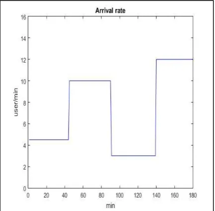
[image:5.595.325.542.529.742.2]The simulation result is done in MATLAB. The fig. 7 shows the arrival rate of the user versus incoming user who connecting the base station (BS). It will have used by the schedule queue. To calculate arrival time, total time divided by the number of samples into total number of channels.
© 2016, IRJET | Impact Factor value: 4.45 | ISO 9001:2008 Certified Journal | Page 901 After Applying the algorithm in the network, the energy
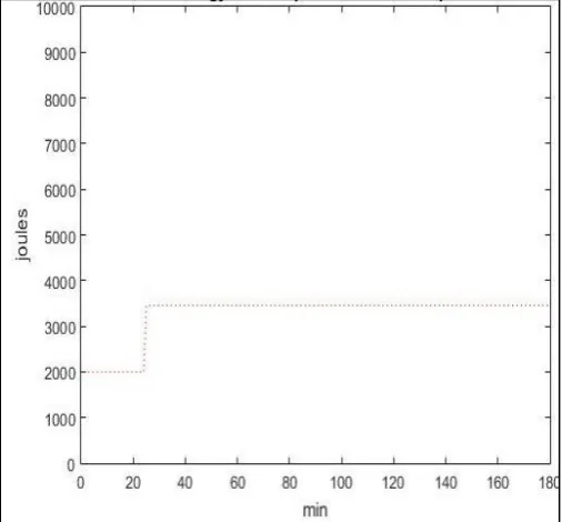
[image:6.595.33.291.153.388.2]consumed by PCC is shown in Fig. 8, when the amount of user connecting the BS is minimum the PCC is activated.
Fig -8: Energy consumed by PCC
[image:6.595.308.565.241.462.2]When the amount of users connecting the base station is maximum the Secondary Carrier Component (SCC) is activated. The fig.9 shows the Energy consumption of SCC.
Fig -9: Energy consumed by SCC
5.1 Comparison between the proposed scheme and
the scheme in [12]
The graph in Chart -1 shows the comparison of proposed scheme and the scheme in [12]. The graph shows that there is huge improvement of energy efficiency and performance which has been increased with compared to the old scheme. By using MIMO and OFDMA with traffic based resource and energy scheduling algorithm. The proposed algorithm is much more efficient than any other existing algorithm.
Chart -1 Comparison of proposed and scheme in [12]
6. CONCLUSION AND FUTURE WORK
In this Project for Phase-I we have done an Energy Efficiency and QoS to Users by proposing Traffic based resource and energy allocation algorithm by using carrier activation algorithm (CC). Here the MIMO - OFDM signal are generated and the signals are classified in to RT and NRT Signals. That signals are queued in the scheduling queue on First in First Out (FIFO) basis and send to the Admission call control mechanism. The result from call admission control mechanism is send to next stage traffic based resource and energy scheduling algorithm and CC algorithm. The obtained results show that the energy efficiency is improved than any other existing systems. In phase-II we are concentrating more on Quality of Service (QoS)
REFERENCES
© 2016, IRJET | Impact Factor value: 4.45 | ISO 9001:2008 Certified Journal | Page 902 [2] Y. Chen, s. Zhang, s. Xu, and g. Y. Li, “fundamental
tradeoffs on green wireless networks,” ieee commun. Mag., vol. 49, no. 6, pp. 30–37, jun. 2011.
[3]
https://www.acs.org.au/news-and-
media/news/2013/ict-global-greenhouse-gas-emissions-double-to-4-by-2020 ict global greenhouse gas emissions double to 4% by 2020.
[4]
https://www.giswatch.org/thematic- report/sustainability-climate-change/carbon-footprint-icts by global information society.
[5] 3gpp green activities available: http:// www.3gpp.org/ftp/information/work_plan/description _releases/
[6] D. Kivanc, g. Li, and h. Liu, “computationally efficient
bandwidth allocation and power control for ofdma,” IEEE trans. Wireless commun., vol. 2, no. 6, pp. 1150– 1158, nov. 2003.
[7] Y.-l. Chung and z. Tsai, “a quantized water-filling packet scheduling scheme for downlink transmissions in lte-advanced systems with carrier aggregation,” in proc. 18th IEEE int. Conf. Software telecommun. Comp. Netw. (ieee softcom), split, croatia, sep. 2010, pp. 275–279. [8] G. Yuan, x. Zhang, w. Wang, and y. Yang, “carrier
aggregation for lte-advanced mobile communication systems,” IEEE commun. Mag., vol. 48, no. 2, pp. 88–93, feb. 2010.
[9] Kaddour, f.z vivier, e.mroueg, “green opportunistic and efficient resource block allocation for lte uplink network”. IEEE transaction on vehicular technology vol., 31 no 16, nov 2014.
[10] Akshay kumar, avik sengupta, ravi tendon, charles clancy “dynamic resource allocation for cooperative spectrum sharing in lte networks” on IEEE transactions on vehicular technology vol 64 , issue: 11 nov 2014. [11] Xiao xiao, xiaoming tao, jianhua lu” energy-eficient
resource allocation in lte-based mimo-ofdma systems with user rate constraints” IEEE transaction on vehicular technology, vol., 64 no.1, jan 2015.
[12] Yao-liang chung “rate-and-power control based energy-saving transmissions in ofdma-based multicarrier base stations” IEEE systems journal, vol. 9, no. 2, june 2015. [13] W. W. L. Ho and y.-c. Liang, “optimal resource allocation for multiuser MIMO-OFDM systems with user rate constraints,” IEEE trans. Veh. Technol., vol. 58, no. 3, pp. 1190–1203, mar. 2009.
[14] L. M. Correia, d. Zeller, o. Blume, d. Ferling, y. Jading, i. Go`ıdor, g. Auer, and l. Van der perre, “challenges and enabling technologies for energy aware mobile radio networks,” IEEE commun. Mag., vol. 48 , no. 11, pp. 66– 72, nov. 2010.
[15] J. Baliga, r. Ayre, k. Hinton, and r. S. Tucker, “energy consumption in wired and wireless access networks,” IEEE commun. Mag., vol. 49 , no. 6, pp. 70–77, jun. 2011. [16] Telecommunication management: study on energy savings management, 3gpp tr 32.826 v10.0.0, tech. Spec. Group services and system aspects, rel. 10, mar. 2010. [17] D. Tse and p. Viswanath, fundamentals of wireless
communication. Cambridge, u.k.: cambridge univ. Press, 2005.
[18] Wei zhang, xiang-gen xia and khaled ben letaief, “space time frequency coding for MIMO-OFDM in next
generation broadband wireless system”, IEEE in wireless communication, June 2004.
[19] Adnan Aijaz, Mati Tshangini, Mohammad Reza Nakhai, Xiaoli Chu “Energy Efficient Uplink Resource Allocation in LTE Networks with M2M/H2H Co-existence under Statistical QoS Guarantees “ on IEEE transaction on communication, issued on vol., 30 No.11 July 2014. [20] xi zhang and ping wang, “Optimal trade-off between
power saving and qos provisioning for multicell cooperation networks”, IEEE Wireless Communications Vol. 20, Issue. 1 Feb 2013.