© 2016, IRJET | Impact Factor value: 4.45 | ISO 9001:2008 Certified Journal | Page 332
RAPID PROTOTYPING TECHNOLOGY AND ITS APPLICATIONS
1. SHASHWAT DWIVEDI, 2.SHALU RAI
1.UG Student, Dept. of Mechanical Engineering, Krishna Institute of Engineering and Technology, Ghaziabad, U.P.,
India [email protected]
2..UG Student, Dept. of Mechanical Engineering, Krishna Institute of Engineering and Technology, Ghaziabad, U.P.,
India [email protected]
---***---Abstract
-
Now a days, one of the critical factors in
competitive technology is “time to market” along
with full proof design. This critical factor indicates
the entire product design cycle from concept to
product design to prototype to manufacturing
process design to actual implementation
.
In this
product design and development process, the
prototyping or model making is one of the
important step to finalize a product which helps in
conceptualization of a design. Thus, we adopt the
method of Rapid Prototyping (RP) for the design
and development of small prototypes or models of
large items to check for errors before actually
making them. The technology which considerably
speeds the interactive product development process
is the concept and practice of Rapid Prototyping
(RP) also called Solid Freeform Fabrication (SFF).
This paper provides a better platform for
researchers,
new
learners
and
product
manufacturers for various applications of RP
models. Subsequently it creates awareness among
the people of recently developing RP method of
manufacturing in product design, developments and
its applications.
Keywords –
CAD Model, Stereolithography, Selective Laser Sintering, Fused Deposition Modeling, Laminated Object Manufacturing, Tessallation, PrototypeIntroduction
A technology wherein the physical modeling of a design is done using a specialized machining technology, Rapid Prototyping (RP) by layer-by-layer material deposition started during early 1980s with the enormous growth in Computer Aided Design and Manufacturing (CAD/CAM) technologies when almost unambiguous solid models with knitted information of edges and surfaces could define a
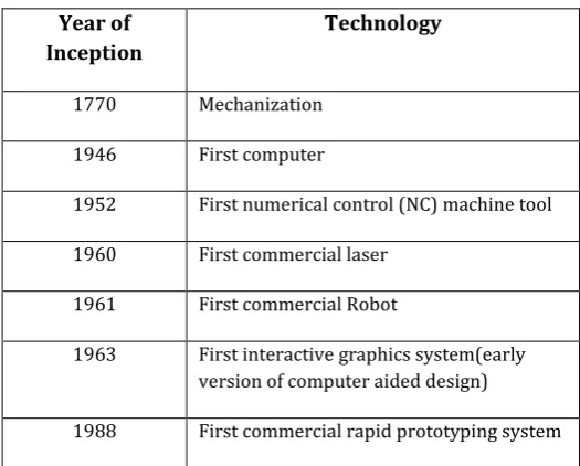
product and also manufacture it by CNC machining. It is also known by several other names like digital fabrication, 3D printing, solid imaging, solid free form fabrication, layer based manufacturing, laser prototyping, free form fabrication, and additive manufacturing.[1] The historical development of RP and related technologies is presented in table 1.
Year of Inception
Technology
1770 Mechanization
1946 First computer
1952 First numerical control (NC) machine tool
1960 First commercial laser
1961 First commercial Robot
1963 First interactive graphics system(early version of computer aided design)
[image:1.595.302.565.350.561.2]1988 First commercial rapid prototyping system
Table 1: Historical development of Rapid Prototyping and related technologies
RP has been high prospective to reduce the cycle and cost of product development. It is an important tool in digital manufacturing in rapid product development. There are a variety of methods that can be used in RP to deposit the material for creating a proto model through RP technique.
© 2016, IRJET | Impact Factor value: 4.45 | ISO 9001:2008 Certified Journal | Page 333
designers to quickly create tangible prototypes of theirdesigns, rather than just two dimensional pictures. Such models make excellent visual aids for communicating ideas with co-workers or customers and can also be used for testing purposes. For example, an aerospace engineer might mount a model airfoil in a wind tunnel to measure lift and drag forces.
[image:2.595.49.277.583.708.2]The process starts with 3D modeling of the product and then STL file is exported by Tessellating the geometric 3D model. In Tessellation various surfaces of a CAD model are piecewise approximated by a series of triangles (figure 1) [2] and co-ordinate of vertices of triangles and their surface normals are listed. The number and size of triangles are decided by facet deviation or chordal error as shown in figure 1. These STL files are checked for defects like flip triangles, missing facets, overlapping facets, dangling edges or faces etc. and are repaired if found faulty. Defect free STL files are used as an input to various slicing softwares. At this stage choice of part deposition orientation is the most important factor as part building time, surface quality, amount of support structures, cost etc. are influenced. Once part deposition orientation is decided and slice thickness is selected, tessellated model is sliced and the generated data in standard data formats like SLC (stereolithography contour) or CLI (common layer interface) is stored. This information is used to move to step 2, i.e., generation of physical model. The software that operates RP systems generates laser-scanning paths (in processes like Stereolithography, Selective Laser Sintering etc.) or material deposition paths (in processes like Fused Deposition Modeling). This step is different for different processes and depends on the basic deposition principle used in RP machine. Information computed here is used to deposit the part layer-by-layer on RP system platform.
Figure 1: The tessellation of a typical surface of CAD model [2](after pandey et al. 2003b)
aesthetic appearance. Prototype is then tested or verified and suggested engineering changes are once again incorporated during the solid modeling stage. Thus the steps involved in the process can be summed up as –
Creation of the CAD model of the (part) design
Conversion of CAD model into Standard Tessellation Language (STL) Format
Slicing of STL file into thin sections
Building part layer by layer
Post processing/finishing/joining
RAPID PROTOTYPING TECHNOLOGIES
Here, few important RP processes namely Stereolithography (SL), Selective Laser Sintering (SLS), Fused Deposition Modeling (FDM) and Laminated Object Manufacturing (LOM) are described
.
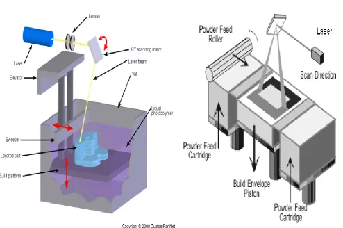
STEREOLITHOGRAPHY
© 2016, IRJET | Impact Factor value: 4.45 | ISO 9001:2008 Certified Journal | Page 334
FIGURE 2 : STERELITHOGRAPHYSELECTIVE LASER SINTERING
–
[image:3.595.49.544.89.417.2]
[3]In Selective Laser Sintering (SLS) process, fine polymeric powder like polystyrene, polycarbonate or polyamide etc. (20 to 100 micrometer diameter) is spread on the substrate using a roller. Before starting CO2 laser scanning for sintering of a slice the temperature of the entire bed is raised just below its melting point by infrared heating in order to minimize thermal distortion (curling) and facilitate fusion to the previous layer. The laser is modulated in such away that only those grains, which are in direct contact with the beam, are affected. Once laser scanning cures a slice, bed is lowered and powder feed chamber is raised so that a covering of powder can be spread evenly over the build area by counter rotating roller. In this process support structures are not required as the unsintered powder remains at the places of support structure. It is cleaned away and can be recycled once the model is complete. The schematic diagram of a typical SLS apparatus is given in figure 3.
Figure 3: Selective Laser Sintering System
FUSED DEPOSITION MODELING
© 2016, IRJET | Impact Factor value: 4.45 | ISO 9001:2008 Certified Journal | Page 335
FIGURE 4: FUSED DEPOSITION MODELLINGPROCESS[3] (after pham and demov,2001)
LAMINATED OBJECT MANUFACTURING
[image:4.595.307.563.112.419.2]Typical system of Laminated Object Manufacturing (LOM) has been shown in figure 5. It can be seen form the figure that the slices are cut in required contour from roll of material by using a 25-50 watt CO2 laser beam. A new slice is bonded to previously deposited slice by using a hot roller, which activates a heat sensitive adhesive. Apart from the slice unwanted material is also hatched in rectangles to facilitate its later removal but remains in place during the build to act as supports. Once one slice is completed platform can be lowered and roll of material can be advanced by winding this excess onto a second roller until a fresh area of the sheet lies over the part. After completion of the part they are sealed with a urethane lacquer, silicone fluid or epoxy resin to prevent later distortion of the paper prototype through water absorption.
FIGURE 5 : LAMINATED OBJECT MANUFACTURING
CASE STUDY
© 2016, IRJET | Impact Factor value: 4.45 | ISO 9001:2008 Certified Journal | Page 336
FIGURE-6 THE POMP ROTOR PROTOTYPE USINGRAPID PROTOTYPING TECHNOLOGY
Applications
RP technology has potential to reduce time required from conception to market up to 10-50 percent [1] (Chua and Leong, 2000). It has abilities of enhancing and improving product development while at the same time reducing costs due to major breakthrough in manufacturing. Therefore, RP technologies are successfully used by various industries like aerospace, automobile, jewelry, coin making, saddletrees etc. Its various applications are listed below-
1.
In medical field
–
Rapid prototyping is used for diagnosis, surgery planning, training and for design and manufacture of the custom implants and also the model of skull.
The 3D CAD(computer aided design) and CAM(computer aided manufacturing) is used for design and development of new products. It shortens the time to market and helps further in research.[5]
The conversion of CT scan or MRI results which are taken as input and then converted in to CAD file then analyze those files with the help of CAM software then production that product with rapid prototyping.
The Physical models enable correct identification of bone abnormality, intuitive understanding of the anatomical issues for a surgeon, implant designers and patients as well.[6]
FIGURE-7 DAMAGED FACIAL SKULL REPLACED BY RP MODEL
2.
In Mechanical Engineering- Analysis and
Planning
Rapid Prototyping is widely used to form and fit large mechanical models.
It provides ease in the flow analysis and indentifying points of stress concentration.
It is often used as a proof of concept and visualizing the object.
Rapid Prototyping has wide applications in the Automobile and Aerospace Industry.
(a) SL model with resection (b) Silicon implant template molded from a tool [1](after pham and demov, 2001)
FIGURE-8 MECHANICAL APPLICATIONS OF RP PROCESS
3. In Electrical appliances
-
The house holding electrical appliances are widely manufactured in the PR techniques. These techniques are very useful for manufacturing the special contours in an electrical item.
4. In textile
-
© 2016, IRJET | Impact Factor value: 4.45 | ISO 9001:2008 Certified Journal | Page 337
any joints with different profiles.6. In Foot-Ware Designing-
The foot-ware for a human comfort is manufacturing in RP technique. This type of foot-ware should have light weight and stronger than the conventional model. And also the complicated design of foot-ware is developed in the RP technique models without any fastener. The reliability is very high compared with conventional model.
7. Architectural Interior design-
An RP technique plays an important role in architectural interior design like stature, wall mountings and toys. [8] The RP model of interior decoration has good surface finishing and aesthetics.
8
. It is also used in crafts, arts and Reverse Engineering applications, Short Production Runs and Rapid Tooling.PART DEPOSITION PLAN
A defect less STL file is used as an input to RP software like Quick SIice or RP Tools for further processing. At this stage, designer has to take an important decision about the part deposition orientation. The part deposition orientation is important because part accuracy, surface quality, building time, amount of support structures and hence cost of the part is highly influenced [9] (Pandey et al., 2004b). In this section various factors influencing accuracy of RP parts and part deposition orientation are discussed.
1.
Factors influencing accuracy
Accuracy of a model is influenced by the errors caused during tessellation and slicing at data preparation stage. Decision of the designer about part deposition orientation also affects accuracy of the model.
Errors due to tessellation: [2] In tessellation surfaces of a CAD model are approximated piecewise by using triangles. It is true that by reducing the size of the triangles, the deviation between the actual surfaces and approximated triangles can be reduced. In practice, resolution of the STL file is controlled by a parameter namely chordal error or facet deviation as shown previously. It has also been
more than that is felt, as shown in figure 9(a). For a spherical model Pham and Demov (2001) proposed that error due to the replacement of a circular arc with stair-steps can be defined as radius of the arc minus length up to the corresponding corner of the staircase, i.e., cusp height (figure 9(b)). Thus maximum error (cusp height) results along z direction and is equal to slice thickness. Therefore, cusp height approaches to maximum for surfaces, which are almost parallel with the x-y plane. Maximum value of cusp height is equal to slice thickness and can be reduced by reducing it; however this results in drastic improvement in part building time.
Therefore, by using slices of variable thicknesses (popularly known as adaptive slicing, as shown in figure 10), cusp height can be controlled below a certain value.
2. Part Building
During part deposition generally two types of errors are observed and are namely curing errors and control errors. Curing errors are due to over or under curing with respect to curing line and control errors are caused due to variation in layer thickness or scan position control. Figures 11 illustrate effect of over curing on part geometry and accuracy. Adjustment of chamber temperature and laser power is needed for proper curing. Calibration of the system becomes mandatory to minimize control errors. Shrinkage also causes dimensional inaccuracy and is taken care by choosing proper scaling in x, y and z directions. Polymers are also designed to have almost negligible shrinkage factors. In SL and SLS processes problem arises with downward facing layers as these layers do not have a layer underneath and are slightly thicker, which generate dimensional error. If proper care is not taken in setting temperatures, curling is frequently observed.
© 2016, IRJET | Impact Factor value: 4.45 | ISO 9001:2008 Certified Journal | Page 338
(b) Error due to replacement of arcs withstair-steps, cusp height [3] (after pham and Demov, 2001)
Figure 9: slicing error
Figure 10: Slicing of a ball, (a) No slicing (b) Thick slicing (c) This slicing
(d) Adaptive slicing [3] (after Pham and Demov, 2001)
3.
PART FINISHING
Poor surface quality of RP parts is a major limitation and is primarily due to staircase effect. Surface roughness can be controlled below a predefined threshold value by using an adaptive slicing [2](Pandey et al., 2003b). Further, the situation can be improved by finding out a part deposition orientation that gives minimum overall average part surface roughness [11](Singhal et al., 2005). However, some RP applications like exhibition models, tooling or master pattern for indirect tool production etc. require additional finishing to improve the surface appearance of the part. This is generally carried by sanding and polishing RP models which leads to change in the mathematical definitions of the various features of the model. The model accuracy is mainly influenced by two factors namely the varying amount of material removed by the finishing process and the finishing technique adopted. A skilled operator is required as the amount of material to be removed from different surfaces may be different and inaccuracies caused due to deposition can be brought down. A finishing technique selection is
important because different processes have different degrees of dimensional control. For example models finished by employing milling will have less influence on accuracy than those using manual wet sanding or sand blasting.
(a) Thicker bottom layer (b) Deformed hole boundary
Figure 11: Over-curing effects on accuracy in Stereolithography
[3] (after Pham and Demov, 2001)
4.
SELECTION
OF
PART
DEPOSITION
ORIENTATION
© 2016, IRJET | Impact Factor value: 4.45 | ISO 9001:2008 Certified Journal | Page 339
understood on connectional drawings, and touch them toverify the shape. It can be used in early design stages to build a conceptual model or in later stages when details are needed. This paper provides an overview of RP Technology and emphasizes on their ability to shorten the product design and development process and classification of a few RP processes used. An attempt has been made to include some important factors to be considered before starting part deposition for proper utilization of potentials of RP processes.
In a short time, rapid prototyping will become a technology that will be used routinely by many design engineers in conjunction with the traditional existing ways of creating scale models of mechanical parts.
REFERENCES
[1] Chua, C.K., Leong, K.F. (2000) Rapid Prototyping: Principe and Applications in manufacturing, world science.
[2] Pandey, P.M., Reddy, N.V., Dhande, S.G. (2003b)Real time adaptive slicing for Fused Deposition Modelling, International journal for machine tool and manufacture, 43(1), pp 61-71.
[3] Pham, D.T., Demov, S.S. (2001) Rapid Manufacturing, Springer-Verlag London ltd.
[4] Dr. Khalid Abd. Elghany, “Rapid Prototyping and Additive Manufacturing in Egypt”, Central Metallurgical Research and Development Institute (CMRDI).
[5] P.S. Maher, R.P. Keatch, K. Donnelly and R.E. Mackay Division of Mechanical Engineering and Mechatronics, University of Dundee, Dundee, UK, and J.Z. Paxton Division of Molecular Physiology, University of Dundee, Dundee, U.K. Construction of 3D biological matrices using Rapid Prototyping Technology Rapid Prototyping Journal15/3 (2009) 204–210
[6] L.C. Hieu, E. Bohez, J. Vander Sloten, H.N. Phien, E. Vatcharaporn, P.H. Binh, Design for Medical Rapid Prototyping for cranioplasty implants Volume 9. Number 3 . 2003.
[7] B. Kieback., A. Neubrand, H. Riedel, Processing techniques for functionally graded materials, Material Science and Engineering A, Vol. 362 2003.
[8] L.Novakova – Marcincinova, J.Novak – Marcincin,
Testing of materials for Rapid Prototyping Fused Deposition
42(19), pp. 4069-4089.
[10] Pandey, P.M., Reddy, N.V., Dhande, S.G. (2003a) Slicing procedures in Layer Manufacturing: A Review, Rapid Prototyping journal, 9(5), pp. 274-288.
[11] Singhal, S.K., Pandey, A.P., Pandey, P.M., Nagpal, A.K.
(2005) Optimum Part Deposition Orientation in Stereolithography, Computer Aided Design and applications, 2(1-4).
](https://thumb-us.123doks.com/thumbv2/123dok_us/8183459.811373/2.595.49.277.583.708/figure-tessellation-typical-surface-cad-model-pandey-et.webp)
![FIGURE 4: FUSED DEPOSITION MODELLING PROCESS[3] (after pham and demov,2001)](https://thumb-us.123doks.com/thumbv2/123dok_us/8183459.811373/4.595.44.535.54.417/figure-fused-deposition-modelling-process-after-pham-demov.webp)
