© 2016, IRJET | Impact Factor value: 4.45 | ISO 9001:2008 Certified Journal
| Page 152
Effects of Application of magnetic field on efficiency of petrol engine
Mr.Sameer chavan
1,
Mrs. Priyanka jhavar
2
M.TECH Thermal Engg
M.TECH Thermal Engg
SSSIST,Bhopal SSSIST,Bhopal
---***---Abstract -
The experiment results in reduction in exhaust gas emissions in I.C. engine using magnetic field. Permanent magnets with different intensity installed on the fuel line show eye catching results. The exhaust gas emissions such as CO and HC are measured by using exhaust gas analyzer. The magnets help to disperse the hydrocarbon cluster into smaller particles which will improve the efficiency of combustion. This will maximize the combustion and thus reduce the unburned hydrocarbon in the emission.Key Words: exhaust gas emissions, magnetic field, fuel line, exhaust gas analyzer, efficiency, unburned hydrocarbon
1.INTRODUCTION
Internal combustion engines represent the main sector of hydrocarbon fuel consumption. On the other hand, as the fuel prices have increased sharply in the past few years due to high demand therefore, engineers and researchers are now interested in improving engines performance (increasing power output and reducing fuel consumption). Many studies suggest that magnetic field has positive effect on the performance of the system. Generally a fuel for internal combustion engine is compound of molecules. Each molecule consists of a number of atoms made up of number of nucleus and electrons, which orbit their nucleus. These molecules have not been realigned, the fuel is not actively interlocked with oxygen during combustion, the fuel molecule or hydrocarbon chains must be ionized and realigned. The ionization and realignment is achieved through the application of magnetic field. Applying a magnetic field to ionizing fuel to be fed to combustion devices we can ensure more complete combustion, obtaining a maximization of the fuel economy, improving the fuel efficiency.
The fuel is subject to the lines of forces from permanent magnets mounted on fuel inlet lines. The magnet for producing the magnetic field is oriented so that its South pole (red) is located adjacent the fuel line and its North pole (blue) is located spaced apart from the fuel line. It is now well accepted that a hydrocarbon fuel can be polarized by exposure to external force such as magnetism. The effect of such magnetism is the production of a moment created by the movement of the outer electrons of a hydrocarbon chain moving the electrons into states of higher principal quantum number. This state effectively breaks down the fixed valance electrons that partake in the bonding process of the fuel
compounds. These states create the condition for free association of fuel particulars. The consequence of treating fuel with a high magnetic field is improved combustion of fuel and consequently increased engine power as well as reduced fuel consumption. Also the engine performance is very important for the better efficiency of vehicle, it is solve by increasing the fuel property. Increases the percentage in the complete combustion of the fuel in combustion chamber, Here we introduce the magnet and there magnetic field in the inlet line of the fuel supply.
2. LITERATURE SURVEY
© 2016, IRJET | Impact Factor value: 4.45 | ISO 9001:2008 Certified Journal
| Page 153
developed such that very few harmful emissions aregenerated, and these could be exhausted to the surroundings without a major impact on the environment. With present technology this is not possible, and after treatment of the exhaust gases to reduce emissions is very important. This consists mainly of the use of thermal or catalytic converters and particulate traps[3]. A hydrocarbon fuel consists of molecules made from atoms of carbon and hydrogen, which are collected by what are called covalent bonds. In such bonds an individual atom will share a pair of electrons with a neighboring atom. Two carbon atoms might share two electrons and by doing so they are held together. Each carbon atom can be connected in four different directions. For example, a given carbon atom might form a sharing partnership with two other carbon atoms in order to be a link in a chain. At the same time this same carbon atom will form a sharing partnership with two hydrogen atoms. Each of the bonds, the C-C bonds or the C-H bonds consists of shared and paired electrons. Normally the two electrons in each covalent bond have balanced opposite spins. “Normal” properties of non-polar molecules such as the hydrocarbons in gasoline, diesel fuel and related materials presuppose such electron spin-balanced chemical bonds [4].Today’s hydrocarbon fuels leave a natural deposit of carbon residue that clogs carburetor, fuel injector, leading to reduced efficiency and wasted fuel. Pinging, stalling, loss of horsepower and greatly decreased mileage on cars are very noticeable. Most fuels for internal combustion engine are liquid, fuels do not combust until they are vaporized and mixed with air. Most emission motor vehicle consists of unburned hydrocarbons, carbon monoxide and oxides of nitrogen. Unburned hydrocarbon and oxides of nitrogen react in the atmosphere and create smog. Generally a fuel for internal combustion engine is compound of molecules. Each molecule consists of a number of atoms made up of number of nucleus and electrons, which orbit their nucleus. Magnetic movements already exist in their molecules and they therefore already have positive and negative electrical charges. However these molecules have not been realigned, the fuel is not actively interlocked with oxygen during combustion, the fuel molecule or hydrocarbon chains must be ionized and realigned. The ionization and realignment is achieved through the application of magnetic field [5].
Hydrogen occurs in two distinct isomeric forms para and ortho. It is characterized by the different opposite nucleus spins. The ortho state of hydrogen has more effective than para state for maximum complete combustion. The ortho state can be achieved by introducing strong magnetic field along the fuel line. Hydrocarbon molecules form clusters, it has been technically possible to
enhance Van der Waals' discovery due to the application of the magnetic field, a high power, permanent magnetic device strong enough to break down, i.e. De-cluster these HC associations, so maximum space acquisition for oxygen to combine with Hydrocarbon [6]. Thus when the fuel flows through a magnetic field, created by the strong permanent magnets, the hydrocarbon change their orientation (para to ortho) and molecules of hydrocarbon change their configuration, at the same time inter molecular force is considerably reduced. This mechanism helps to disperse oil particles and to become finely divided.
This has the effect of ensuring that the fuel actively interlocks with oxygen and producing a more complete burn in the combustion chamber. It has been reported that declustering of the Hydrocarbon fuel molecules takes place due to application of magnetic field resulting in better atomization of the fuel better mixing of the fuel-air mixture [7].
When the fuel flows through a magnetic field, created by the strong permanent magnets, the hydrocarbon change their orientation (para to ortho) and molecules of hydrocarbon change their configuration, This helps in lowering the amount of un-burnt fuel. It reduces the Carbon Monoxide and Hydrocarbon percentages in the exhaust gases, thus enhancing the thermal efficiency of the I. C. Engine
Many experimental tests have been carried out in the world for explaining the magnetic power for treating fuel lines for more efficient combustion and less pollution. Their invention relates to the control of combustion and pollution by means of magnetic field processing of fuel lines under a controlled magnetic field [7].
In terms of emission, for every 1kg of fuel burnt, there is about 1.1kg of water vapor and 3.2kg of carbon dioxide produced (BP Australia Limited, 2000). Unfortunately, there is no automobile engines have 100% combustion and so there is also a small amount of products of incomplete combustion and these are carbon monoxide (denoted CO), unburned hydrocarbons, oxides of nitrogen, commonly called NOx and sulphur dioxide. This gaseous lead to hotter exhaust gas emission
© 2016, IRJET | Impact Factor value: 4.45 | ISO 9001:2008 Certified Journal
| Page 154
The results obtained from this study agreed with those ofWashburn et al. (2001) indicating that vehicles manufactured by different manufacturers produce different percentages of vehicle emissions. This reflects the engine technology and emission control system used by these manufacturers. Accordingly, there is a significant relationship between car manufacturer and emission rates.
Vehicle it should have an injection fuel supply system, no matter what the manufacturing country is. More attention should be given with a Japanese vehicle to engine size and maintenance period. Small engine “less than 1500 cc”, with a periodic maintenance of once “at least every three months” is a rule with Japanese vehicles in order to reduce pollutants from emissions. However, the most aspect which should be considered with a German vehicle is the fuel type (super or unleaded). The results support that only new vehicles should be used by Jordanian citizens and that the vehicles with carburetor fuel supply system should not be imported to Jordan in order to reduce and control vehicle emissions [8].
he energy of permanent magnets was used in this research for the treatment of vehicle fuel (Iraqi gasoline), to reducing consumption, as well as reducing the emission of certain pollutants rates. The experiments in current research comprise the using of permanent magnets with different intensity (2000, 4000, 6000, 8000) Gauss, which installed on the fuel line of the two-stroke engine, and study its impact on gasoline consumption, as well as exhaust gases. For the purpose of comparing the results necessitated the search for experiments without the use of magnets. The overall performance and exhaust emission tests showed a good result, where the rate of reduction in gasoline consumption ranges between ( -1 ) %, and the higher the value of a reduction in the rate of 1 % was obtained using field intensity 6000 Gauss as well as the intensity 9000 Gauss. It was found that the percentages of exhaust gas components (CO, HC) were decreased by 30%, 40% respectively, but CO2 percentage increased up to 10%. Absorption Spectrum of infrared and ultraviolet radiation showed a change in physical and chemical properties in the structure of gasoline molecules under the influence of the magnetic field. Surface tension of gasoline exposed to different intensities of magnetic field was measured and compared with these without magnetization[8].
Most fuels for internal combustion engine are liquid, fuels do not combust until they are vaporized and mixed with air. Most emission motor vehicle consists of unburned
hydrocarbons, carbon monoxide and oxides of nitrogen. Unburned hydrocarbon and oxides of nitrogen react in the atmosphere and create smog. Smog is prime cause of eye and throat irritation, noxious smell, plat damage and decreased visibility. Oxides of nitrogen are also toxic. Even when fuel is still clear and bright, microscopic fuel components agglomerate forming larger clusters and organic compounds. (i.e. chaotic form) This continuous process affects combustion and engine performance which causing loss of power, excessive fuel consumption, smoking engines, damage to injection systems and carbon soot build up in lube oil, emission filters and catalytic converters. There are different methods (MPFI, EGR, PCV, catalytic) used which not only gives proper combustion of fuel in engine but also minimize the rate of emission through I.C. engine. One new modern technique to reduce the emission & gives proper combustion is use of magnetic fuel conditioner.[9]
3. WORKING PRINCIPLE OF MAGNET
Fig.3.1Flow Of Fluid Under Magnetic Field
© 2016, IRJET | Impact Factor value: 4.45 | ISO 9001:2008 Certified Journal
| Page 155
F = qV × BWhere, q is the charge on a particle, V is its velocity, and B is the magnetic field.
3.1 Effect of Magnetic Field on Fuel Molecule
Hydrogen occurs in two distinct isomeric forms Para and ortho shows in the below fig.3.4. It is characterized by the different opposite nucleus spins. The ortho state of hydrogen has more effective than para state for maximum complete combustion. The ortho state can be achieved by introducing strong magnetic field along the fuel line. Hydrocarbon molecules form clusters, it has been technically possible to enhance van der Waals' discovery due to the application of the Magnetic field, a high power, permanent magnetic device strong enough to break down, i.e. de-cluster these HC associations, so maximum space acquisition for oxygen to combine with hydrocarbon.
(A) Para State of Hydroge (B) Ortho State Of Hydrogen Fig.3.2 Schematic View Hydrogen
Thus when the fuel flows through a magnetic field, created by the strong permanent magnets, the hydrocarbon change their orientation (para to ortho) and molecules of hydrocarbon change their configuration, at the same time inter molecular force is considerably reduced. This mechanism helps to disperse oil particles and to become finely divided.
4. EXPERIMENTAL SETUP AND READINGES UNDER
DIFFERENT LOADING CONDITIONS
4.1 Experimental set up and procedure
1. First the entire connections have been checked. 2. Fuel tank is filled with petrol.
3. Fuel weight measuring unit placed to ON position 4. Cooling water pump is started
5. EPA software is started.
6. Load indicator panel placed on ON position 7. Ignition switch is put on.
8. Interfaced software system is put on. 9. Engine is started.
10. Accelerated the engine . 11. Then set the load for observations. 12. Select the rpm for that load.
13. All the corresponding input and output parameter readings have been recorded into respective observation tables.
14. Exhaust gas analyzer sensor is inserted in the engine exhaust gas pipe and measure all emissions.
15. After that change the load and again record all measurements.
16. Repeat the procedure for 2,3 and 4 pairs of magnet. 17. compare the result without magnet and with magnet and plot result.
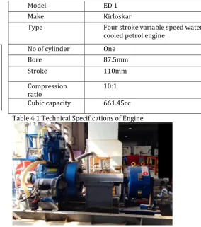
4.2 Technical Specifications of Engine:
The performance tests were carried out on a single cylinder, four stroke,variable speed water cooled Petrol engine. The setup consists of an engine, an eddy current dynamometer, and an exhaust gas analyzer.
Model ED 1
Make Kirloskar
Type Four stroke variable speed water cooled petrol engine
No of cylinder One
Bore 87.5mm
Stroke 110mm
Compression
ratio 10:1
[image:4.595.291.576.239.561.2]Cubic capacity 661.45cc
Table 4.1 Technical Specifications of Engine
Fig 4.1 Photographic view of single cylinder four stroke petrol engine
© 2016, IRJET | Impact Factor value: 4.45 | ISO 9001:2008 Certified Journal
| Page 156
[image:5.595.36.273.121.226.2]4.5 Exhaust Gas Analyser
Fig 4.2 Exhaust Gas Analyzer
The exhaust gas analyzer is used to measure exhaust emissions from the engine during experimental tests. It is measures gases such as HC, CO, O2 and CO2 concentrations at each and every load. This procedure was done twice one for without magnet situation and other for with magnet situation, and results were compared.
IRJET sample template format ,Conclusion content comes here. Conclusion content comes here Conclusion content comes here Conclusion content comes here Conclusion content comes here Conclusion content comes here Conclusion content comes here Conclusion content comes here Conclusion content comes here Conclusion content comes here Conclusion content comes here Conclusion content comes here Conclusion content comes here . Conclusion content comes here
5.EFFECT OF MAGNETIC FIELD ON
PERFORMANCE PARAMETERS OF VARIABLE SPEED
PETROL ENGINE
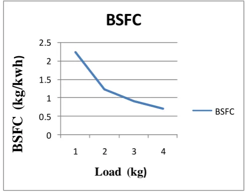
5.1 Observation tables for without magnet.
Reading of specific fuel consumption & fuel
consumption without magnet at various load
condition .
SPEED
(rpm)
LOAD
(kg)
BSFC
(kg/kwh)
FUEL
(kg/h)
1850
1
2.24
0.64
1825
2
1.22
0.69
1746
3
0.90
0.73
1661
4
0.69
0.71
Table 5.1.1 Reading of BSFC & Fuel
consumption at various load condition without
magnet
0 0.5 1 1.5 2 2.5
1 2 3 4
B
S
F
C
(
k
g
/k
w
h
)
Load (kg
)
BSFC
BSFC
Fig. 5.1.1 Graph of Brake specific fuel
consumption vs Load without magnet
2)
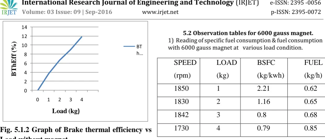
Reading of Brake thermal efficiency without
magnet at various load condition
SPEED
(rpm)
LOAD
(kg)
BThEff
(%)
1850
1
3.64
1825
2
6.66
1746
3
9.04
[image:5.595.309.556.233.426.2]1661
4
11.78
Table 5.1.2 Reading of Breake thermal efficiency
[image:5.595.310.560.533.686.2]© 2016, IRJET | Impact Factor value: 4.45 | ISO 9001:2008 Certified Journal
| Page 157
Fig. 5.1.2 Graph of Brake thermal efficiency vs
Load without magnet
3) Reading of Mechanical efficiency without magnet
at various load condition
SPEED
(rpm)
LOAD
(kg)
Mech Eff
(%)
1850
1
6.65
1825
2
12.57
1746
3
18.34
[image:6.595.311.551.317.466.2]1661
4
23.25
Table 5.1.3 Reading of Mechanical efficiency at
various load condition without magnet
0 5 10 15 20 25
0 1 2 3 4
M
ec
h
e
ff
(
%)
Load (kg
)
Mech Eff (%)
[image:6.595.44.281.336.497.2]Mech Eff (%)
Fig. 5.1.3 Graph of Mechanical efficiency vs Load
without magnet
5.2 Observation tables for 6000 gauss magnet. 1) Reading of specific fuel consumption & fuel consumption with 6000 gauss magnet at various load condition.
Table 5.2.1 Reading of Bsfc & fuel consumption
at various load condition with 6000 gauss magnet.
0 1 2 3
1 2 3 4
B
S
F
C
(
k
g/
k
w
h
)
Load (kg
)
BSFC
BSFC
Fig. 5.2.1 Graph of Brake specific fuel
consumption vs Load with 6000 gauss magnet.
2) Reading of Brake thermal efficiency with 6000
Gauss magnet at various condition
SPEED
(rpm)
LOAD
(kg)
BTh Eff
(%)
1850
1
3.69
1830
2
7.04
1842
3
10.22
1730
4
10.29
Table 5.2.2 Reading of brake thermal efficiency at
various load conditions with 6000 gauss magnet
.
SPEED
(rpm)
LOAD
(kg)
BSFC
(kg/kwh)
FUEL
(kg/h)
1850
1
2.21
0.62
1830
2
1.16
0.65
1842
3
0.8
0.68
1730
4
0.79
0.85
0 2 4 6 8 10 12 14
0 1 2 3 4
B
T
h
E
ff
(
%
)
Load (kg
)
[image:6.595.313.547.581.718.2]© 2016, IRJET | Impact Factor value: 4.45 | ISO 9001:2008 Certified Journal
| Page 158
0 5 10 15
0 1 2 3 4
BT
h
Ef
f
(%
)
Load (kg)
BTh Eff
BTh Eff
Fig. 5.2.2 Graph of Brake thermal efficiency vs
load with 6000 gauss magnet
3) Reading of mechanical eff with 6000 Gauss
magnet at various condition
SPEED
(rpm)
LOAD
(kg)
Mech eff
(%)
1850
1
6.61
1830
2
12.78
`1842
3
18.97
1730
4
23.51
Table 5.2.3 Reading of mechanical efficiency at
various load condition with 6000 gauss magnet.
0 10 20 30
0 1 2 3 4
m
ec
h
eff
(
%
)
Load (kg)
Mech eff
[image:7.595.37.265.76.263.2]Mech eff
Fig. 5.2.3 Graph of Mechanical efficiency vs Load
with 6000 gauss magnet
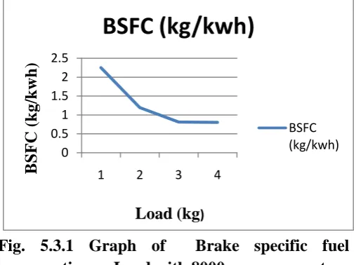
5.3 Observation tables for 8000 gauss magnet.
1) Reading of specific fuel consumption & fuel consumption with 8000 gauss magnet at various load condition .
Table 5.3.1 Reading of Bsfc & fuel consumption
at various load condition with 8000 gauss magnet.
0 0.5 1 1.5 2 2.5
1 2 3 4
B
S
F
C (
k
g/k
w
h
)
Load (kg
)BSFC (kg/kwh)
BSFC (kg/kwh)
Fig. 5.3.1 Graph of Brake specific fuel
consumption vs Load with 8000 gauss magnet.
2) Reading of Brake thermal efficiency with 8000
Gauss magnet at various condition
SPEED
(rpm)
LOAD
(kg)
BTh
Eff
(%)
1845
1
3.63
SPEED
(rpm)
LOAD
(kg)
BSFC
(kg/kwh)
FUEL
(kg/h)
1845
1
2.25
0.63
1825
2
1.19
0.97
1835
3
0.81
0.69
[image:7.595.310.564.434.623.2]© 2016, IRJET | Impact Factor value: 4.45 | ISO 9001:2008 Certified Journal
| Page 159
1825
2
6.83
1835
3
10.07
[image:8.595.290.565.52.292.2]1724
4
10.17
Table 5.3.2 Reading of brake thermal efficiency at
various load conditions with 8000 gauss magnet.
0 2 4 6 8 10 12
1 2 3 4
BTh
Eff
(%)
Load (kg)
BTh Eff (%)
BTh Eff (%)
Fig. 5.3.2 Graph of Brake thermal efficiency vs
load with 8000 gauss magnet
3) Reading of mechanical eff with 8000 Gauss
magnet at various condition
SPEED
(rpm)
LOAD
(kg)
Mech
eff (%)
1845
1
6.65
1825
2
12.81
1835
3
18.97
[image:8.595.39.200.282.398.2]1724
4
23.51
Table 5.3.3 Reading of Mechanical efficiency at
various load conditions with 8000 gauss magnet.
0 5 10 15 20 25
1 2 3 4
M
ec
h
e
ff
(%
)
Load (kg
)Mech eff (%)
Mech eff (%)
Fig. 5.3.3 Graph of Mechanical efficiency vs Load
with 8000 gauss magnet
6) RESULT
1) Brake specific fuel consumption
Table 6.1.1 Reading of BSFC at various load
condition with 6000, 8000 gauss magnet.
Load
(kg) Without magnet 6000 gauss 8000 gauss
1 2.24 2.21 2.25
2 1.22 1.16 1.19
3 0.90 0.8 0.81
[image:8.595.304.568.367.532.2] [image:8.595.45.277.582.741.2]© 2016, IRJET | Impact Factor value: 4.45 | ISO 9001:2008 Certified Journal
| Page 160
0 0.5 1 1.5 2 2.5
1 2 3 4
B
S
F
C(
k
g/k
w
h
)
Load (kg)
6000 GAUSS
8000 GAUSS
Fig.6.1.1 Graph of Brake specific fuel
consumption vs Load with 6000,8000 gauss
magnet.
2) Brake thermal efficiency
Load
Without
magnet
6000
gauss
8000
gauss
1
3.64
3.69
3.63
2
6.66
7.04
6.83
3
9.04
10.22
10.07
[image:9.595.311.569.337.481.2]4
11.78
10.29
10.17
Table 6.1.2 Reading of brake thermal efficiency at
various load conditions with 6000 ,8000 gauss
magnet
.
0
5
10
15
1 2 3 4
B
r
a
k
e
t
her
m
a
l
e
ff
(%)
Load (kg)
Without
magnet
6000
gauss
8000
gauss
Fig. 6.1.2 Graph of Brake thermal efficiency vs
load with 6000 8000 gauss magnet
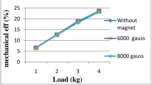
3) Mechanical efficiency
Load
Without
magnet
6000
gauss
8000
gauss
1
6.65
6.61
6.65
2
12.57
12.78
12.81
3
18.34
18.97
18.97
4
23.25
23.51
23.51
Table 6.1.3 Reading of Mechanical efficiency at
various load conditions with 6000,8000 gauss
magnet.
0 5 10 15 20 25
1 2 3 4
m
ec
h
an
ical e
ff
(%
)
Load (kg)
Without magnet
6000 gauss
8000 gauss
Fig. 6.1.3 Graph of Mechanical efficiency vs Load
with,6000,8000 gauss magnet
3. CONCLUSIONS
1) Magnetic field effect on brake specific fuel consumption
The experimental results show that the fuel consumption of engine was less when the engine with magnet than that without magnet at higher load. Always less amout of fuel was consumed with fuel with magnetic field the BSFC vs load graph is shown in fig 6.1.1.The effective result are obtained with 2000 & 4000 gauss magnet than 6000 & 8000 gauss magnet.
[image:9.595.37.249.592.727.2]© 2016, IRJET | Impact Factor value: 4.45 | ISO 9001:2008 Certified Journal
| Page 161
3) Magnetic field effect on mechanical efficiency The experimental results show that the mechanical efficiency of engine was less when the engine without magnet than the engine with magnet at higher load. The variation of mechanical efficiency vs load is as shown in fig 6.1.3.it is clear that with the application of magnetic field the mechanical efficiency goes on increasing. The effective result are obtained with 2000 & 4000 gauss magnet than 6000 & 8000 gauss magnet.