© 2015, IRJET.NET- All Rights Reserved
Page 297
INVESTIGATION OF SURFACE FINISH AND MRR DURING ABRASIVE
ASSISTED DRILLING ON
POLYMER MATRIX COMPOSITE MATERIAL.
Dilpreet Singh
1, Gurmeet Singh Chhatwal
2, Mandeep Kumar
31
Dept. of Mechanical Engineering, Punjab College of Engineering & Technology, Lalru Mandi, Punjab, India
2Assistant Professor, Dept. of Mechanical Engineering, Punjab College of Engineering & Technology, Lalru Mandi,
Punjab, India
3
Assistant Professor, Dept. of Mechanical Engineering, Chandigarh University, Gharuan, Punjab, India
---***---Abstract - This report is concerned with investigating
the Surface finish when drilling POLYMER MATRIX COMPOSITE (E-Glass) with HSS drill. This study included drilling of PMC with supply of Sic abrasive, Alumina Oxide Abrasive having grain size 800, 1000, 1200 mesh size through abrasive slurry system & with Coolant. Abrasives not only used for cooling purpose but also increases the surface finish, MRR and reduce tool wear. Experiments were conducted on a CNC Drilling machine. Taguchi is applied for executing the planning of experiments. The drilling parameters namely Feed rate (mm/min) ,Spindle speed (rpm) ,Type of abrasive grain size ,Slurry Concentration ,Type of Abrasive (Silicon Carbide, Alumina oxide), were optimized using multiple performance characteristics for Surface Finish. The result shows that the feed rate, Type of Abrasive & slurry concentration are the most significant factors which affect the Surface finish in the drilling can be effectively improved by using this approach
Key Words:
Abrasives, ANOVA, Drilling, Taguchi
Technique, Polymer Matrix Composite material
E-Glass , Surface roughness, MRR.
1. INTRODUCTION
Drilling is one of the most fundamental machining processes. It is most frequently performed in material removal and is used as a preliminary step for many operations such as reaming, tapping and boring. It is moving toward high speed applications for productivity enhancement. Drilling is a process of producing round hole in solid material or enlarging existing hole with the use of multi-point cutting tools called drill or drill bits. Various cutting tools are 297blind hole in a solid material. It has found that high production machining and drilling with high cutting velocity, feed and depth of cut is inherently associated with generation of large amount of heat and high cutting temperature which reduces accuracy
and tool life. Drilling is an essential operation in the assembly of the structural frames of automobiles and aircrafts. The life of a joint can be critically affected by the quality of the drilled holes. The growing demand for higher productivity, product quality and overall economy in manufacturing by machining, grinding and drilling, particularly to meet the challenges thrown by liberalization and global cost competitiveness, insists high material removal rate and high stability and long life of the cutting tools. However, high production machining and grinding with high cutting velocity, feed and depth of cut is inherently associated with generation of large amount of heat and high cutting temperature. Such high cutting temperature not only reduces dimensional accuracy and tool life but also impairs the surface finish of the product. One estimate is that 75% of all metal-cutting material removed comes from drilling operations. Drilled holes are characterized by their sharp edge on the entrance side and the presence of burrs on the exit side (unless they have been removed).
We all know that the 20th century has witnessed revolutions in a number of fields like computer,
Radar, space, missiles, etc. but the most interesting changes have taken place in the area of polymer matrix composites. In the literature review we will review the surface roughness and material removal rate, Taguchi technique.
2.
LITERATURE REVIEW
© 2015, IRJET.NET- All Rights Reserved
Page 298
drilled holes. The predicted values are compared withexperimental data and are found to be in good agreement [1].
Yogendra Tyagi
investigated that the drilling of mild steel with the help of CNC drilling machine operation with high speed steel by applying Taguchi methodology has been reported. The Taguchi method is applied to formulate the experimental layout to ascertain the element of impact each optimum process parameters for CNC drilling machining with drilling operation of mild steel. A L9 array, Taguchi method and analysis of variance (ANOVA) are used to formulate the procedure tried on the change of parameter layout. The available material study in focuses optimization of CNC Drilling machine process parameters to provide good surface finish as well as high material removal rate (MRR).The surface finishing and material removal rate have been identified us quality attribute and are assumed to be directly related to productivity. The selection of optimal machining parameters i.e., spindle speed, depth of cut and feed rate) for drilling machine operations was investigated in order to minimize the surface roughness and to maximize the material removal rate [2].Arshad Noor Siddiquee had focused on optimizing deep drilling parameters based on Taguchi method for minimizing surface roughness. The experiments were conducted on CNC lathe machine using solid carbide cutting tool on material AISI 321 austenitic stainless steel. Four cutting parameters such as cutting fluid, speed, feed and hole-depth, each at three levels except the cutting fluid at two levels were considered. Taguchi L18 orthogonal array was used as design of experiment. The signal-to-noise (S/N) ratio and the analysis of variance (ANOVA) was carried out to determine which machining parameter significantly affects the surface roughness and also the percentage contribution of individual parameters. Confirmation test was conducted to ensure validity of the test result. It is observed that the surface finish for deep drilling process can be improved effectively through this approach [3].
B.V.Kavad had studied that drilling is an important process for making and assembling components made from Glass Fiber Reinforced Plastic (GFRP). Various processes like conventional drilling, vibration assisted drilling and ultrasonic assisted drilling have been attempted in order to maintain the integrity of the material and obtain the necessary accuracy in drilling of GFRP. This paper attempts to review the influence of machining parameter on the de-lamination damage of GFRP during drilling. In conventional machining feed rate, tool material and cutting speed are the most influential factor on the de-lamination hence machining at higher speed, harder tool material and lower feed rate have lesser de-lamination of the GFRP. Vibration assisted drilling and Ultrasonic
assisted drilling have lesser thrust and hence lesser de-lamination compared to conventional drilling, which indicates that both vibration assisted drilling and Ultrasonic assisted drilling are more appropriate for drilling of GFRP [4].
B. Rameshinvestigated that a non laminated Glass Fiber Reinforced Plastic (GFRP) composite manufactured by pultrusion process was drilled with a coated cemented carbide drill. The thrust force and torque during drilling were acquired through piezoelectric dynamometer and damage factor was measured using metallurgical microscope. Taguchi’s orthogonal array and analysis of variance (ANOVA) were employed to study the influence of process parameters such as feed and spindle speed on thrust force, torque and damage factor. The optimum level of process parameters towards minimum thrust force, minimum torque and lower damage factor were obtained to achieve defect controlled drilling of GFRP composites. Correlations for thrust force, torque and damage factor with process parameters were established using statistical software MINITAB 15. Among the process parameters examined, feed significantly influences both the thrust force and torque with 88.52% and 92.83% respectively whereas the influence of spindle speed on the above was relatively insignificant. The influence of feed and spindle speed on damage factor at both entrance and exit of the work piece was insignificant [5].
3. MACHINING SETUP
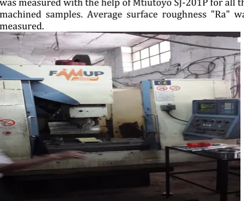
For the entire experiment Computer Numerical Machine (FAMUP Machining Centre) was used shown in fig 1. The abrasive slurry of Silicon Carbide and Alumina Oxide of grit size 800, 1000, 1200 was cutting fluid for experimentation. The slurry was used with varying concentration of 20%, 25%, and 30%. The work material used for the experimentation is Polymer matrix composite (E-Glass). Then surface roughness of machined surface was measured with the help of Mtiutoyo SJ-201P for all the machined samples. Average surface roughness "Ra" was measured.
[image:2.595.309.552.551.751.2]© 2015, IRJET.NET- All Rights Reserved
Page 299
3.1 Polymer Matrix Composite
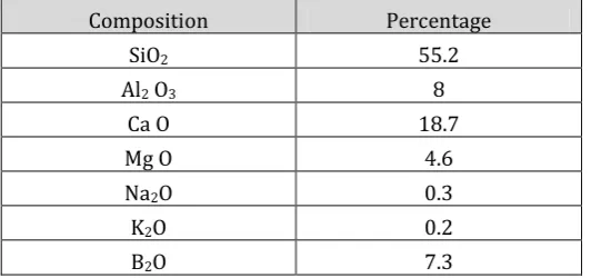
A composite material contains more than one component. The composite material is mostly related to polymer composites, in which the polymer is the matrix and the fibers are reinforcements. Glass fibers are the most common fibers of all reinforcing fibers for polymeric matrix composites (PMC). It is when the resin systems are combined with reinforcing fibers such as glass that exceptional properties can be obtained. The resin matrix spreads the load applied to the composite between each of the individual fibers and also protects the fibers from damage caused by abrasion and impact. High strength and stiffness, ease of molding complex shapes, high environmental resistance all coupled with low densities, make the resultant composite superior to metals for many application . The composition of the work piece is shown in Table 1.
[image:3.595.303.567.228.325.2]
Table -1 Chemical composition of E-Glass
Composition Percentage
SiO2 55.2
Al2 O3 8
Ca O 18.7
Mg O 4.6
Na2O 0.3
K2O 0.2
B2O 7.3
3.2 Abrasive
A material of extreme hardness that is used to shape other materials by a grinding or abrading action .Abrasive materials may be used either as loose grains, as grinding wheels, or as coatings on cloth or paper. They may be formed into ceramic cutting tools that are used for machining metal in the same way that ordinary machine tools are used. Because of their superior hardness and refractory properties, they have advantages in speed of operation, depth of cut, and smoothness of finish. The manmade abrasives are silicon carbide, Aluminum oxide, Cubic boron nitride.
4. EXPERIMENTATION
In the present investigation, five different process parameters have been selected as already discussed. The tool material factor has two levels whereas all other parameters such as depth of cut, table speed, grit size and slurry concentration have three levels each. As per the requirements of the study, L18 orthogonal array has come out as one of the possible solutions for designing the experiments. Here, the term ‘signal’ represents the desirable value (mean) and the ‘noise’ represents the undesirable value (standard deviation). The percentage contribution of various process parameters on the selected performance characteristic can be estimated by
[image:3.595.30.301.324.449.2]performing analysis of variance test (ANOVA). The five process parameters are considered including type of abrasive, feed rate, speed of spindle, abrasive grit size, slurry concentration are shown in table 3.1. Taguchi’s robust design of experiments (DOE) methodology was used to plan the experiments statistically. Minitab 16 has been used to model the effect of process parameters. The signal to noise ratio (S/N ratio) is obtained using Taguchi’s methodology.
Table -2 Control Parameters and Their Levels
Factors Levels Level 1 Level 2 Level 3
Type of Abrasive (A) 2 Al2 O3 Si C
Feed Rate (B) 3 100 200 300
Speed of Spindle (C) 3 1500 2000 3000
Abrasive size (D) 3 800 1000 1200
Slurry const. (E) 3 15% 25% 35%
In this research, five different process parameters with three levels have been selected. As per Taguchi, L18 orthogonal array has come out as one of the possible solutions for designing the experiments.
Table-3 L18 orthogonal array Exp.
No.
Abrasi ve
Feed rate
Speed (RPM)
Ab. Size
Slurry Const.
1 Si C 100 1500 800 15
2 Si C 100 2000 1200 25
3 Si C 100 3000 1000 35
4 Si C 200 1500 800 25
5 Si C 200 2000 1200 35
6 Si C 200 3000 1000 15
7 Si C 300 1500 1200 15
8 Si C 300 2000 1000 25
9 Si C 300 3000 800 35
10 Al2 O3 100 1500 1000 35
11 Al2 O3 100 2000 800 15
12 Al2 O3 100 3000 1200 25
13 Al2 O3 200 1500 1200 35
14 Al2 O3 200 2000 1000 15
15 Al2 O3 200 3000 800 25
16 Al2 O3 300 1500 1000 25
17 Al2 O3 300 2000 800 35
[image:3.595.308.565.402.770.2]© 2015, IRJET.NET- All Rights Reserved
Page 300
5. RESULT AND DISCUSSION
Table-4 Observation tableExp. No. MRR S/N Ratio Ra S/N
1 1.38 2.813 5.35 -14.57
2 1.33 2.500 4.82 -13.65
3 1.51 3.569 6.23 -15.89
4 1.88 5.468 5.01 -14
5 1.99 5.995 6.55 -16.32
6 1.59 4.038 5.49 -14.79
7 1.97 5.884 5.99 -15.55
8 1.99 5.995 5.67 -15.08
9 2.17 6.729 6.95 -16.84
10 1.61 4.152 6.78 -16.63
11 1.53 3.668 6.19 -15.84
12 1.53 3.668 5.98 -15.54
13 2.17 6.729 7.24 -17.19
14 1.79 5.071 6.54 -16.32
15 1.97 5.884 6.34 -16.04
16 2.05 6.246 8.05 -18.11
17 2.35 7.406 9.04 -19.13
18 2.29 7.186 7.34 -17.31
Fig-2 Plot for S/N ratio (Surface roughness)
Fig-3 Plot for Mean (Surface roughness)
Feed rate affects the surface roughness the most. Surface finish is better with minimum feed rate. With the increase in feed rate, surface roughness also gets increased. So from three different values for feed rate, it is observed that surface finish is maximum at 100mm/min and minimum when feed rate is 300mm/min. Surface roughness is also affected by speed. It is observed that surface roughness is maximum if speed is 3000rpm & it is minimum at 1500 rpm.
The use of coarser grit size promotes the increase in surface roughness, thus deteriorating the surface quality. Use of coarse abrasive grains result in increase in rate of fractures on the surface thereby increasing the surface roughness. On the other hand use of finer grit size decrease the surface roughness. 1200 grain size provides better surface finish than 1000 & 800 grit sizes. It is also concluded that surface finish is best when slurry concentration is 20% and 25%. Above this value surface became rough.
5.1 Percentage Improvement
It is observed that the lower value of surface roughness is obtained with the silicon abrasive assisted drilling as compared to the drilling with coolant. This can be explained on the basis of low removal rate during the silicon abrasive assisted drilling. As the removal rate is low, very less cavities found on the surface of PMC (E-Glass) during drilling.
Table-5 Comparison of Surface Roughness with abrasive slurry of silicon and drilling with coolant
Exp. No.
Abrasive Assisted Drilling (Ra)(µm)
Drilling With Coolant (Ra)(µm)
% Improvement
1
5.353
5.6
4
2
4.817
6.266
23
3
6.227
7.85
21
4
5.01
6.23
20
5
6.55
7.977
18
6
5.49
8.4
35
7
5.99
7.55
21
8
5.673
8.373
32
9
6.947
8.52
18
% improvement =
Drilling with coolant (Ra) - Abrasive drilling (Ra) *100 Drilling with coolant (Ra)
© 2015, IRJET.NET- All Rights Reserved
Page 301
Table-5 Comparison of Surface Roughness with abrasiveslurry of Aluminum and drilling with coolant
Exp. No. Abrasive Assisted Drilling (Ra)(µm)
Drilling With Coolant (Ra)(µm)
% Improvement
10
6.783
5.6
-21
11
6.193
6.266
1
12
5.983
7.85
24
13
7.235
6.23
-16
14
6.544
7.977
18
15
6.339
8.4
25
16
8.047
7.55
-7
17
9.044
8.373
-8
18
7.337
8.52
14
There is 3.33 % improvement in the surface finish during the aluminum abrasive assisted drilling
6. ANALYSIS OF VARIANCE (ANOVA)
Table-6 ANOVA for S/N ratio (Surface Roughness)
S
ource D
O
F SS
MS F P %
C
on
tr
ibu
ti
on
A 1 13.199 13.199 46.11 0 40.05
B 2 8.7976 4.3988 15.37 0.002 26.7
C 2 0.0119 0.0059 0.02 0.98 0.04
D 2 0.1345 0.0672 0.23 0.796 0.41
E 2 8.5217 4.2609 14.88 0.002 25.86
Errors 8 2.2902 0.2863 6.95
Total 17 32.9549
Table-7 ANOVA for S/N ratio (MRR)
S
ource D
O
F SS
MS F P %
C
on
tr
ibu
ti
on
A 1 2.7705 2.7705 19.88 0.002 7.01
B 2 31.3805 15.6902 112.58 0 79.4
C 2 0.0355 0.0177 0.13 0.882 0.09
D 2 0.9442 0.4721 3.39 0.086 2.39
E 2 3.2783 1.6392 11.76 0.004 8.29
Errors 8 1.115 0.1394 2.82
Total 17 39.524
As per this experiment data for surface roughness, type of abrasive is the important factor to consider for surface finish during the abrasive assisted drilling of polymer matrix composite material with a percentage of 40.05% and the feed rate having also significant contribution of 26.70%. Beside this, slurry concentration has 25.86% contribution. The abrasive size having 0.41%, speed having 0.04%.
For MRR feed rate with percentage contribution of 79.40%, Slurry concentration (8.29%), Type of abrasive (7.01) are the significant factors. Abrasive size (2.39%), and speed with (0.09%) are in-significant parameters as their value is below 2.77%.
7. CONCLUSIONS
In case of surface roughness, silicon abrasives of 1200 mesh size with 25 % concentration and a feed rate of 100mm/min with 2000 rpm rotational speed found to be optimized parameters for abrasive assisted drilling.
In case of slurry (silicon) versus drilling with coolant, the average improvement in surface roughness is 21.33 % while for slurry of alumina versus drilling with coolant, the average surface roughness improvement is 3.33%. In case of Material Removal Rate, Aluminum abrasives of 800 mesh size with 35 % concentration and a feed rate of 300mm/min with 2000 rpm rotational speed found to be optimized parameters for abrasive assisted drilling. In case of Abrasive assisted drilling (slurry silicon) versus drilling with coolant, the average improvement in material removal rate is 2.02 % while for Abrasive assisted drilling (slurry alumina) versus drilling with coolant; the average material removal rate improvement is 10.6%.
Out of all selected parameters, feed rate, type of abrasive and slurry concentration is significantly affecting the surface roughness in abrasive assisted drilling of polymer matrix composite (E-Glass). Rpm and abrasive size gives small effect on surface roughness. Minimum value of Surface roughness is obtained at higher speed and higher abrasive size and at moderate slurry concentration. Material removal is affected by feed rate and type of abrasive. RPM and abrasive size gives mild effect on MRR.
REFERENCES
[1] Arshad Noor Siddique, Zahid A. Khan, Pankul Goel, Mukesh Kumar, Gaurav Agarwal, Noor Zaman Khan (2014) “Optimization of Deep Drilling Process Parameters ofAISI 321 Steel using Taguchi Method” 3rd International Conference on Materials Processing and Characterisation (ICMPC 2014)
[2] B.V.Kavad, A.B.Pandey, M.V.Tadavi, H.C.Jakharia (2014) “A Review Paper on Effects of Drilling on Glass
© 2015, IRJET.NET- All Rights Reserved
Page 302
Conference on Innovations in Automation andMechatronics Engineering, (ICIAME 2014)
[3] B. Arefi, A. Settari , P. Angman,(2005) “Analysis and simulation of erosion in drilling tools” B. Arefi et al. / Wear 259 (2005) 263–270
[4] B. RAMESH, S. JOSEPH CYRIL SHARAN, R.
KAVIALAGAN , (2013) “experimental investigation and optimization in drilling gfrp polymeric composites using taguchi and anova” IJMPE (2315-4489, Vol-2)
[5] C.C. Tsao, H. Hocheng (2007), “Effect of tool wear on
delamination in drilling composite materials”
International Journal of Mechanical Sciences 49 (2007) 983–988
[6] Erkki Jantunen (2002) “A summary of methods applied to tool condition monitoring in drilling” International Journal of Machine Tools & Manufacture 42 (2002) 997–1010
[7] Gergely DEZSO, .Gyula VARGA, .Ferenc SZIGETI (2011), “ Investigation the correlation between technological parameters and the wear in case of drilling with minimal lubrication” International Journal of Engineering (ISSN 1584 – 2665)
[8] Gul Tosun, Mehtap Muratoglu (2003) “The drilling of Al/SiCp metal–matrix composites. Part II: workpiece surface integrity” Composites Science and Technology 64 (2004) 1413–1418
[9] H.S. Liu, B.Y. Lee, Y.S. Tarng (1998) “In-process prediction of corner wear in drilling operations” Journal of Materials Processing Technology 101 (2000) 152-158
[10]H. Liu , J. Wang, N. Kelson , R.J. Brown,(2004) “A study of abrasive waterjet characteristics by CFD simulation” Journal of Materials Processing Technology 153–154 (2004) 488–493
[11]J.Pradeep Kumar, P.Packiaraj (2012), “effect of drilling parameters on surface roughness, tool wear, material removal rate and hole diameter error in drilling of ohns” International Journal of Advanced Engineering Research and Studies( E-ISSN2249– 8974)
[12]M. Ramulu, P.N. Rao, H. Kao (2002) “Drilling of (Al2O3)p/6061 metal matrix composites” Journal of Materials Processing Technology 124 (2002) 244– 254
[13]Quan Yanming, Zhou Zehua (1998) “Tool wear and its mechanism for cutting SiC particle-reinforced aluminium matrix composites” Journal of Materials Processing Technology 100 (2000) 194-199
[14]Scott F. Miller, Peter J. Blau, Albert J. Shih ,(2006), “Tool wear in friction drilling” International Journal of Machine Tools & Manufacture 47 (2007) 1636–1645
[15]Yanming QUAN, Wenwang ZHONG (2009)
“Investigation on drilling-grinding of CFRP” Higher Education Press and Springer-Verlag 2009
[16] Yogendra Tyagi, Vedansh Chaturvedi, Jyoti Vimal (2012), “ Parametric Optimization of Drilling Machining Process using Taguchi Design and ANOVA Approach” International Journal of Emerging Technology and Advanced Engineering. (ISSN 2250-2459)
[17]Kapil Kumar Goyal, Vivek Jain, Sudha Kumari (( 2014 ) “ Prediction of Optimal Process Parameters for Abrasive Assisted Drilling of SS304” 3rd International
Conference on Materials Processing and
Characterisation (ICMPC 2014)
BIOGRAPHIES
1Dilpreet Singh completed his graduation from PTU in
Mechanical Engineering.
Worked as quality engineer for 3 years. Now working as an Assistant Professor from last 4 years
2 Er. Gurmeet Singh Chhatwal Post-Graduated from GNE College, Ludhiana. Working as Assistant Professor at PCET Lalru Mandi