© 2016, IRJET ISO 9001:2008 Certified Journal Page 2154
IMAGE DENOISING USING DIGITAL SIGNAL PROCESSOR
R Durgagopal
1, V. Krishnanaik
23M. Lakshmi Narayana
3, M.Lakshmanayak
4B.Sreenu
51
Asstociate Professor, ECE Dept. Joginpally B.R. Engineering College, JNTUH Hyderabad, India.
2
Ph.D Research Scholar from India & Associate Professor, Aksum University, Aksum, ET
3,4 5Assistant Professor, LITAM,JNTUK, Sattenapalli, Guntur, Andhra Pradesh, India
---***---Abstract -
The point of this is to denoising of the ECG signal using TMS320C6713 DSK processor. Here the use of adaptive filtering technique gives us the idea of effective method for filtering of a signal. The ECG signal is generated in Matlab software and is used as the optimum source samples i.e., it is used as the desired signal which is to be compared with the input signal. Here we use LMS algorithm as an adaptive algorithm for processing and analyzing of the ECG signal. Adaptive filters are best utilized as a part of situations where signal settings or framework limitations are gradually varying and filter is confirmed to adjust for this change. There are many adaptive algorithms of which LMS algorithm is one of them and is more accurate and precise. The C6713 is modern DSK processor which has both floating and fixed point processors. The earlier versions only had the fixed point processing. The random signal is removed from the ECG signal with the help of LMS filter code that is loaded into CCS (Code Compressor studio) and the output from the processor is verified.Key Words: DSP, DSK, Image Denoising, TMS,PLC,ECG, LMS Algorithm, CCS Code. Matlab.
1.
INTRODUCTION
The target of this thesis is to present a denoising technique for an ECG signal using TMS320C6713 processor. There are many ways in which denoising of an signal can be done. This technique is used to remove the noise which occur due to various effects and should be removed to get a desired and required signal. The TMS320C6713 DSK Processor is an improvised version in the family of C6x as it is capable both floating and fixed point processing. The denoising of the ECG signal is done by using Adaptive filter. The adaptive filter is a type of a linear filter which updates the weights of the filter by using an Adaptive algorithm. Here the filter is gone through initially the training period which is done by taking a known signal, the filter coefficients are updated and then testing period is done by various signals. In the upcoming sections we will learn inn detail about the processor and the adaptive signal processing and the filtering technique adopted.
1.1 ECG SIGNAL
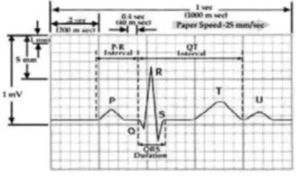
ECG is the electrical demonstration of the contractile movement of the heart. They are sensed by the electrodes which are stanch to the surface of skin and can be chronicled by a device which is outside of body. This noninvasive procedure of recording is known an Electrocardiogram. An ECG is used not only to compute the regularity and rate of the heartbeats but also to know the size and position of the heart’s chambers, any damage’s present in the heart, and the special effects of drugs/devices which are used to control the heart, for instance pacemaker. A typical ECG signal constitutes the PQRST complex. A PQRST complex consists of a complete cardiac cycle. In a cardiac cycle: a P wave, a QRS Complex, a T wave. The baseline of ECG can be determined by measuring the part of the Signal preceding the P wave and the part following the T wave. For normal person, generally, the baseline is almost isoelectric at about 0mV. However, in a sick heart the baseline may be above or below the isoelectric line. In the figure 1, a cardiac cycle is shown denoting the PQRST Complex.
[image:1.595.313.527.495.624.2]
Fig 1: A Complete Cardiac Cycle
For each wave considered by amplitude and the duration. In the table given below, the limitations of the ECG Signal for a normal being are summarized.
© 2016, IRJET ISO 9001:2008 Certified Journal Page 2155 ventricles. Since, they have a huge muscle mass as wave. The
Q wave signify the interventricular septum’s depolarisation. S wave is any descending deflection found after the occurrence of the R wave. The T wave represents the ventricle’s repolarization. The period from the start of the QRS complex to peak of T wave is signified as the complete refractory retro when another action potential cannot be triggered by an external stimuli. The second part of the T wave is new action denoted to as the relative refractory period where easily a potential can be triggered. Sometimes, a U wave may follow a T wave
1.2 NECESSITY OF DENOISING TECHNIQUE
Denoising is a process of removing the noise from a signal. Here we use adaptive signal processing for the noise cancellation. The filter designed here for the denoising technique is LMS filter. By removing the noise from the signal one can get the desired and accurate signal. In case of an ECG signal it is very important for filtering of the signal so that the signal generated can be analyzed and clinician can give a detailed analysis on one person’s heart beat. The noise in signal may be due to various effects such as noise due to main supply, interference etc. the filter here differentiates between the noise and the original signal. It compares the given signal with the ECG signal which is given as a desired signal to the LMS filter. The filter automatically updates the weights so that it could separate the noise and the desired signal. Sifting is the most collective for every signal, as every signal frequency spectra does not comprise of valid data. For
instance 60 Hz AC control lines, which existing in most of surroundings will yield noise if the signal is improved.
1.3 OBJECTIVE
The main objective here is removing of the noise from the ECG signal using TMS320C6713 processor.
Developing of the LMS algorithm in C language which could be able to run in the CCS and can be loaded into the TMS processor.
Generation of the ECG signal and the random noise in the matlab. The each wave of the ECG signal is generated separately by using fourier transform and summed up for generating an entire ECG signal. File management is used so as to import the desired and random sample values that are generated in matlab into CCS. The random signal should be generated should be in the size of the ECG signal generated.
Interfacing of TMS320C6713 processor with the desktop or PC.
The signal thus obtained is viewed in the oscilloscope which is connected to the TMS processor by adding up few libraries to CCS.
2. ADAPTIVE FILTER
Adaptive filters are best utilized as a part of situations where signal settings or framework constraints are gradually varying and filter is confirmed to adjust for this change. An powerful however straightforward capable filter is known as the linear adaptive combiner, which is simply a flexible FIR. LMS scheme is a pursuit calculation that can be utilized to give the method to modifying the channel coefficients.
In conventional IIR and FIR digital filters, one assumes that course constraints to regulate the about filter features to be known. They may fluctuate by varying time, however the way of the disparity is thought to be acknowledged. In numerous real-world problems these may have a substantial vulnerability in a few limitations on account of insufficient earlier trial information of the procedure. A few limitations may be required to alter with time, however the nature of transformation is unpredictable. In such situations it is suitable to proposal of the filter that is self learning so that it can familiarize the situation for any variation that comes into play.
© 2016, IRJET ISO 9001:2008 Certified Journal Page 2156 The factors of a adaptive filter will be acclimated to adjust
for fluctuations in the signal input, the signal output, or the system constraints. As opposed to unbending, a adaptive structure can take in signal qualities and trail moderate vicissitudes. A adaptive filter could be exceptionally valuable when we have instability in the attributes of signal.
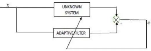
Theoretically, adaptive structure is genuinely straight forward. A large portion of the adaptive structures can be depicted by the arrangement indicated in Figure 2. It is an essential adaptive structure in which the output y of the filter is contrasted and likened to the a signal signified as ‘d’ to produce a error e, that is then again feedback to adaptive filter. This error acts as a input for the adaptive scheme, which alters the adaptable filter to fulfill nearly foreordained norms or guidelines. The signal that is desired is generally the supreme troublesome one to acquire. One of the first inquiries that likely strikes a chord is: Why we are attempting to produce the signal that is desired at y on the off chance that we recognize it? In numerous solicitations the desired signal does exist some place in the scheme or is known. The test in smearing adaptive strategies is to make sense of how to get the signal that is desired, which to mark the output y, and which to mark the error.
The quantities of the adaptive filter can be balanced, or streamlined, utilizing a LMS scheme taking into account the error signal. Here we talk about just the LMS looking calculation ith a direct combiner, even if there are a few techniques for carrying out adaptive filtering. The output obtained from the adaptive filter from Figure 2 is given by
where wk(n) represents N coefficients at a particular time n. The convolution equation given from the above equation is regular run-through to use the updation of the weights denoted by w for coefficients that are accompanying with situations involved in adaptive filtering and the neural networks.
The recital measure is required to govern how better the filter is. The measure is centered on error signal
which is dissimilarity among the desired signal d(n) and the filter to yeild y(n).The coefficients wk(n) are balanced such that a mean square error is minimized. The mean square error is a function that can be represented as E[e2(n)], where E here signifies the expected value. Since
there are K weights a slope of mean squared function is needed. An appraisal can be found utilizing the slope of e2(n), giving
which signifies the LMS scheme. The above equation provides a straightforward and powerful and an very effective way for updating the coefficients, without any necessity for the average, and is used for implementation of the adaptive filter. Generally, input of adaptive filter is given as x(n) and β is the convergence rate and also the precision of the reworking process.
For every particular time snigified as n, each weight, wk(n) is redesigned or supplanted by another weight, in view of (2), unless the error signal e(n) is zero. Later the filter's output y(n), the error e(n) and for each of the weights wk(n) are redesigned for a particular time , another example is gained (from ADC), the adjustment methodology is rehashed for an alternate time. Note from (2.), the weight values are not redesigned when e(n) turns into zero.
2.1 ADAPTIVE STRUCTURES
There are various adaptive configurations that are used for diverse kind of solicitations in the filteration process.
1. For cancellation of noise
The above Figure 3 demonstrates the adaptive scheme in changed for the cancellation of noise solicitation. The obtained desired signal d is tainted by uncorrelated added noise. The input for filter is the noise n1 is correlated along
the initial noise n. The noise n1 might originate from the
similar source like of n however altered by the earth. The filter's output y is adjusted to the noise . At the point when this happens, the blunder signal methodologies the desired signal d. The general output is the the error but not the filter output y. On the off chance that ‘d’ is uncorrelated with ‘n’, the technique is to reduce E(e2), where ‘E(n)’ is the
anticipated value. The expected value is usually not known, so it is estimated with the instant function itself. The component of signal, ‘E(d2)’, will be unchanged and only the
noise component ‘E[(n-y)2]’ will be reduced.
2. For identification of system:
© 2016, IRJET ISO 9001:2008 Certified Journal Page 2157 Fig 3. Adaptive filter structure for cancellation
of noise
Fig4: Adaptive filter structure for identification of system
3.
TIME DOMAIN ADAPTIVE FILTERING
ALGORITHMS
There are numerous calculations used to change the coefficients of the digital filter with a specific end goal to match the desired response and also conceivable. The LMS Algorithm is the more effective of the calculations in light of the fact that it is the most proficient regarding both storage requirement and undoubtedly computational complexity. Like the steepest descent algorithm on which the LMS algorithm is based upon, the fundamental LMS algorithm redesigns the filter coefficients after every sample.
STEEPEST DESCENTALGORITHM
The steepest descent algorithm is an old tool for numerically discovering the base estimation of a function, with respect to the slope of that function. Steepest descent utilizes the slope function (or the scalar subordinate, if the function is single-valued) to focus in which direction a function is expanding or diminishing most quickly. Every progressive cycle of the algorithm moves along this direction for a predetermined step size, and the recomputes the slope to focus the new bearing to travel. The strategy for steepest descent is a valuable tool for sign transforming on the grounds that it can be connected iteratively.
We can apply the steepest descent algorithm to the Wiener filter in such a path, that at every new step we can ascertain another set of filter coefficients. Utilizing the steepest descent strategy, we can approach a minimum error value in generally couple of iterations, and we can track a signal that
adjusts so as to apply new least coefficients to every new form of the signal. It is imperative to utilize a steepest descent approach, or other quick minimization calculation so that the channel coefficients can be upgraded all the more immediately then the following data test is gotten. The steepest descent algorithm can be set by the formula:
LMS ALGORITHM:
The realization of the regular wiener filter mostly gives the answer to the least squares approximation, apart from the domain of signal processing. The least squares answer with the input matrix x and the output vector y is given by
β = (XTX)-1 XTY
The fundamental thought behindhand LMS channel is to develop the optimal filter weights (R-1P), by redesigning the filter weight in a way to congregate with the optimal filter weights. The scheme begins by pretentious small values of weights (zero mostly), and at every step, by discovering the slope of the mean square error, the coefficients are u[dated. That is, if the MSE-slope is infers, the error will continue growing absolutely, if the same coefficient is utilized for additional reiterations, which implies we have to lessen the values of weights. In the similar way, if the slope is negative, we have to increase the values. In this way, the fundamental weight upgrade mathematically is given by
where represents the mean square error. The negative sign indicates that, there is a necessity to change the weights in a direction contradictory to that of gradient slope.
DERIVATION OF LMS ALGORITHM
The idea behindhand LMS filter is to routine steepest descent algorithm to find values of filter coefficients which will reduce the cost function. The cost function can be represented by the equation
C(n) = E{ | e(n)2| }
Where e(n) is the error signal at the present sample n and
© 2016, IRJET ISO 9001:2008 Certified Journal Page 2158 Where ∇ is the gradient operator
Here ∇ ( ) is the vector that points to steepest ascent related to cost function. To get the slightest of the cost function we want to take a step in the contradictory course of ∇ ( ).
Expressing ∇ ( ) in mathematical expressions we get the equation as
Here µ/2 depicts the step size i.e., the adaption constant. That depicts that we have established a sequential update algorithm that decreases the value of the cost function.
The problem that occurs here is that this scheme is not realizable until we get the value of
E{x(n) e’(n)}.
For many schemes we get the expectation function E{x(n) e’(n)} usually estimated. This could be done by using a unbiased estimator.
Where N is the figure of samples we use for the estimation.
The simplest case is N=1
Then for the simplest case the update algorithm becomes as follows
The above equation constitutes for the update algorithm for the LMS filter.
THE IMPORTANCE OF µ AND N
A critical piece of the calculation is the overhauling of the channel coefficients as would be commonplace for all adaptive filter calculations’ is basic for the overhaul and must be picked precisely to guarantee the channel merges. Redesigning the channel coefficients is critical on the grounds that this is the piece of the code that administers how well the channel will meet to the sought reaction. Another component that has a key part in this jovining is the quantity of channel coefficients N.
4.
TMS320C6713 DIGITAL PROCESSOR
The TMS320C6713 is made of the VLIW modeling, which is extremely well suited for numerically serious algorithms. The interior program memory is organized with the goal that an aggregate of eight instructions can be gotten each cycle. For instance, with a clock rate of 225MHz, the C6713 is equipped for getting eight 32-bit instructions for every period of 1/(225 MHz) or 4.44 ns.
© 2016, IRJET ISO 9001:2008 Certified Journal Page 2159
FIGURE: TMS320C6713 Structure
5.
CODE COMPRESSOR STUDIO
CCS gives an IDE to fuse the product apparatuses. CCS incorporates instruments for code era, for example, a C compiler, a ASSEMBLER, and a linker. It has graphical abilities also, and undergoes real time troubleshooting. It gives a simple to-utilize programming device to build and troubleshoot programs. The C compiler assembles a C source program with .c extension to deliver an get together source document with .asm extension.The assembler collects an.asm source record to create a machine dialect article document with extension.obj. The linker joins article documents and item libraries as information to deliver an executable document with .out extension. This executable document speaks to a linked common object file format (COFF), prominent in Unix-based frameworks and embraced by a few producers of advanced signal processors. This executable record can be stacked and run specifically on the C6713 processor. The straight get together source document with augmentation .sa, which is a combination of C and gathering code. A direct enhancer streamlines this source record to make a assembly file with .ASM extension (like the undertaking of the C compiler).
GENERATION OF ECG SIGNAL IN MATLAB:
The ECG signal is developed in the matlab. Each wave is individually generated and then it is summed to form an ECG signal. A random signal is also generated in the matlab software is whose samples are added to the ECG signal samples. The two samples should have the same sample size.
The use of a software for generation of the ECG signal has numerous points of interest in the recreation of ECG waveforms. Initial one is identified with the sparing of time and other one is evacuating the troubles of bringing genuine ECG signals with intrusive and noninvasive strategies. The
ECG signal generated in the matlab is easy to analyze each of the waves discretely.
The ECG signal generated in the matlab is generated in such a way that the user can either use the default values used in the code for generation of the signal or can enter on his own the amplitude, duration and time for individual signals.
File management procedure is used in matlab and CCS so that the ECG signal samples generated in can be stored in the text file whenever the program is made to run the matlab software creates the text file so that the sample values of the ECG signal and the random samples are stored in two different text files. Then the LMS filter code which is written in CCS imported the text files that are generated by the matlab software and uses them as the desired signal(ECG signal) and the input signal(Random signal). The ECG signal generated with the default signal has a heartbeat of 72BPM.
The default values taken are as follows: Any occasional capacities which fulfill dirichlet's condition can be communicated as a progression of called extents of sin and cos terms of frequencies which happen as a various of fundamental frequency.
ECG sign is intermittent with principal frequency dictated by the heart beat. It additionally fulfills the dirichlet's conditions:
The function is single value also is finite over the given interval.
It is totally integrable.
There ought to be limited number of maxima and minima between specific interims.
It also has finite amount of cutoffs.
Hence fourier series could be used as in lieu of ECG signal. So, the individual waves of the ECG signal such as P, Q, QRS, T, U waves can be individually be generated with the help of the fourier transform. Here we see the generation of the P wave and also the QRS complex the rest of the waveforms are also generated in a similar manner. The generation of these waves is shown in next section
6.
OUTPUTS AND CALCULATIONS
We may perceive that a solitary time of an ECG sign is a mixture of triangular and sinusoidal wave frames. Every huge highlight of ECG sign can be spoken to by moved and scaled variants one of these waveforms as demonstrated as follows.
© 2016, IRJET ISO 9001:2008 Certified Journal Page 2160 P, T and U bits can be spoken to by triangular
waveforms.
When we produce each of these bits, they can be added at last to get the ECG signal. Lets take QRS waveform as the inside the whole gang shifting happens as for this some piece of the signal.
Generation of a intermittent QRS portion of ECG signal:
FIGURE: Generating The QRS Waveform
Generation of P WAVE of ECG Signal
Thus the ECG signal generated from matlab is
© 2016, IRJET ISO 9001:2008 Certified Journal Page 2161
TMS320C6713 PROCESSOR OUTPUT
The ECG signal samples and the random signal samples (ECG signal plus noise) that are generated through matlab are given to the LMS filter with ECG signal as the desired signal and the random signal as the input signal. The LMS filter is initially gone through the training period with the known signal by considering the optimum weights around 4. During the training period the weights or coefficients of the LMS filter are obtained approximately 4. Now in the testing period the input signal generated from the matlab is been compared with the desired signal and the outputs resulted are as follows
CONCLUSION AND FUTURE WORK
The outputs from the TMS320C6713 processor were extracted successfully and plotted with the help of oscilloscope. The LMS calculation taking into account Adaptive separating is proposed and actualized effectively. The execution of the calculation has been checked effectively on CCS and the calculation is discovered to be exceedingly proficient. It is found after effective execution that denoising system for ECG sign utilizing the TMS processor can be effectively removed by utilizing Least Mean Square (LMS) calculation for tap-weight vectors. The LMS calculation is executed by in C. The training and the testing periods of the adaptive filter are successfully implemented.
The results are obtained from the processor but are not precise and accurate. The adaptive filter used here has only gone through 1000 samples during the training period. The
filter should be going through more training period for accurate results. The adaptive filter technique used here is efficient and can produce much precise results by training it with more samples so that the filter coefficients are reached up to their optimum values. But the extraction techniques may change with time and hence more efficient and error free techniques will be developed in future.
REFERENCES
[1] Rulph Chassaing, Digital signal and its Applications with C6713 and C6416 DSK, Wiley Publications,2005.
[2] Bernard Widrow and Samuel D Stearns, Adaptive Signal Processing, Prentice-Hall Inc,1985.
[3] S.Manikandan, Implementation of Active Noise Filter for real-time Noise Reduction using TMS processor. [4] TMS320C6000 Programmer’s Guide, SPRU198G, Texas
Instruments, Dallas, TX, 2002.
[5] Leslie Cromwell, Biomedical Instrumentation and Measurements, Prentice Hall of India.
[6] P. S. Hamilton and W. J. Tompkins.”Quantitative investigation of qrs detection rules using the mit/bih arrhythmia database,”Biomedical Engineering, IEEE Transactions on, BME-
33(12):1157–1165, Dec. 1986.
BIOGRAPHIES
Mr.R.Durga Gopal, He obtained his M.Tech from CVR College of Engineering College, Hyderabad and pursuing Ph.D from JNTUH. Currently working as a Associate Professor in Joginpally B.R. Engineering College, He is having 9+ years of relevant work experience in Academics, Teaching, Industry & Research. His area of research includes Signal Processing, Communications and VLSI.
Shri VANKDOTH KRISHNANAIK,
Ph.D - Research Scholar from India. And Currently working as Assoc. Professor, in the Department of Electrical & Computer Engineering, College of Engineering & Tech, Aksum University, He has 16+ years of relevant work experience in Academics, Teaching, Industry & Research.