© 2016, IRJET | Impact Factor value: 4.45 | ISO 9001:2008 Certified Journal | Page 1258
Comparison Analysis of devices for mitigation of harmonics due to
non-linear loads
Narinder Singh
1, Ishan Thakur
21M.Tech, Electrical Engineering, Baddi University, H.P, INDIA
2Astt. Professor, Electrical Engineering, Baddi University, H.P, INDIA
---***---Abstract -
The given papers is that the application of the FACTS controllers employed in grid for maintaining the Reactive Power, Voltage Stability, Power issue throughout the method of the transmission of the facility in higher attributes. during this paper the simulation model of the UPQC, STATCOM & SSSC Facts Controllers area unit taken for observation so a winning comparison will be administered so the output result will be additional helpful for the more application. The Simulation is employed here to hold out the total method. during this paper the when the comparison of all 3 devices the most effective one is chosen among them for results. Active power filters are relatively new and rather costly but have important advantages that should be watched carefully which are inherently current limiting, have no resonance problems, intelligent and adaptable, can be configured to either correct the full spectrum of harmonics or to target specific harmonics and being able to compensate for harmonics without fundamental frequency reactive power concerns. The paper starts with a brief overview of harmonic distortion problems and their impacts on electric power quality, how the active power filter solved this problem.Key Words: STATCOM, SSSC, UPQC, Voltage Stability, Reactive Power.
1.INTRODUCTION
A flexible alternating current transmission system (FACTS) could be a system composed of static instrumentality used for the AC transmission of current. it's typically an influence electronics-based system. FACTS is outlined by the IEEE as "a power electronic based mostly system and different static instrumentality that offer management of 1 or additional AC gear mechanism parameters to boost controllability and increase power transfer capability."[1]The 1st FACTS installation was at the C. J. Slatt station in Northern region. this is often a five hundred kV, 3-phase sixty rate station, and was developed by EPRI, the Bonneville Power Administration and General public utility.[2] Many devices contribute to reactive power compensation and voltage profile. A cable, thanks to its physical characteristics, provides reactive power beneath light-weight loading and consumes it beneath serious
loading conditions. installation voltages square measure controlled through the availability and consumption of reactive power. In general terms, decreasing reactive power margin causes voltage fall, while increasing reactive power margin causes voltage rise. A voltage collapse occurs when the system is trying to serve much more load than the voltage can support. Voltage instability is basically caused by an unavailability of reactive power support in an area of the network, where the voltage drops uncontrollable. Lack of reactive power may essentially have two origins: firstly, a gradual increase of power demands without the reactive part being met in some buses or secondly, a sudden change in the network topology redirecting the power flows in such a way that the required reactive power cannot be delivered to some buses. Introducing FACTS devices is the most effective way for utilities to improve the voltage profile and voltage stability margin of the system.[3]
STATCOM: A static synchronous compensator (STATCOM), also known as a "static synchronous condenser" ("STATCON"), is a regulating device used on alternating current electricity transmission networks. It is based on a power electronics voltage-source converter and can act as either a source or sink of reactive AC power to an electricity network. If connected to a source of power it can also provide active AC power. It is a member of the FACTS family of devices. Usually a STATCOM is installed to support electricity networks that have a poor power factor and often poor voltage regulation. There are however, other uses, the most common use is for voltage stability. A STATCOM is a voltage source converter (VSC)-based device, with the voltage source behind a reactor. The voltage source is created from a DC capacitor and therefore a STATCOM has very little active power capability. However, its active power capability can be increased if a suitable energy storage device is connected across the DC capacitor.
© 2016, IRJET | Impact Factor value: 4.45 | ISO 9001:2008 Certified Journal | Page 1259
or a capacitive reactance in series with the transmission line. The heart of SSSC is a VSI (voltage source inverter) that is supplied by a DC storage capacitor. With no external DC link, the injected voltage has two parts: the main part is in quadrature with the line current and emulates an inductive or capacitive reactance in series with the transmission line, and a small part of the injected voltage is in phase with the line current to cover the losses of the inverter. When the injected voltage is leading the line current, it will emulate a capacitive reactance in series with the line, causing the line current as well as power flow through the line to increase. When the injected voltage is lagging the line current, it will emulate an inductive reactance in series with the line, causing the line current as well as power flow through the line to decrease.
UPQC: A Unified Power Flow Controller or (UPQC) is an electrical device for providing fast-acting reactive power compensation on high voltage electricity transmission networks. It uses a pair of three-phase controllable bridges to produce current that is injected into a transmission line using a series transformer. The controller can control active and reactive power flows in a transmission line. The UPQC uses solid state devices, which provide functional flexibility, generally not attainable by conventional thyristor controlled systems. The UPQC is a combination of a static synchronous compensator (STATCOM) and a static synchronous series compensator (SSSC) coupled via a common DC voltage link. The UPQC concept was described in 1995 by L. Gyugyi of Westinghouse. [4]
2. SIMULATION:
BLOCK DIAGRAM THEORY - A Unified Power Flow Controller (UPQC) is used to control the power flow in a 765 kv transmission system. The UPQC located at the left end of the 75-km line L2, between the 765 kv buses B1 and B2, is used to control the active and reactive powers fIt consists of two 100-MVA, three-level, 48-pulse GTO-based converters, one connected in shunt at bus B1 and one connected in series between buses B1 and B2. The shunt and series converters can exchange power through a DC bus. The series converter can inject a maximum of 10% of nominal line-to-ground voltage (28.87 kV) in series with line L2.lowing through bus B2 while controlling voltage at bus B1
.
Fig 1. UPQC Detailed Model
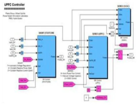
This pair of converters can be operated in three modes: Unified Power Flow Controller (UPQC) mode, when the shunt and series converters are interconnected through the DC bus.
[image:2.595.307.547.301.486.2]When the disconnect switches between the DC buses of the shunt and series converter are opened, two additional modes are available: Shunt converter operating as a Static Synchronous Compensator (STATCOM) controlling voltage at bus B1 Series converter operating as a Static Synchronous Series Capacitor (SSSC) controlling injected voltage, while keeping injected voltage in quadrature with current
Fig 2. UPQC Controller
The mode of operation as well as the reference voltage and reference power values can be changed by means of the “UPQC GUI” block. The principle of operation of the harmonic neutralized converters is explained in another demo entitled “Three-phase 48-pulse GTO converter”.
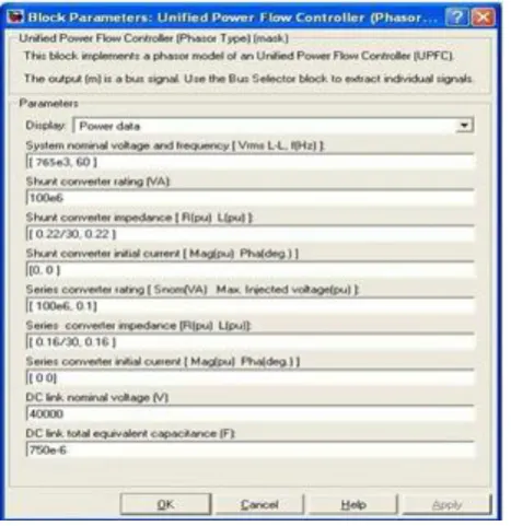
© 2016, IRJET | Impact Factor value: 4.45 | ISO 9001:2008 Certified Journal | Page 1260 When operating in UPQC mode, the magnitude of the
series injected voltage is varied by varying the Sigma conduction angle, therefore generating higher harmonic contents than the shunt converter.
[image:3.595.36.270.164.405.2]
Fig 3. Block Parameter UPQC
As illustrated in this demo, when the series converter operates in SSSC mode it generates a “true” 48-pulse waveform. The natural power flow through bus B2 when zero voltage is generated by the series converter (zero voltage on converter side of the four converter transformers) is P=+870 MW and Q=-70 Mvar. In UPQC mode, both the magnitude and phase angle and the series injected voltage can be varied, thus allowing control of P and Q. The UPQC controllable region is obtained by keeping the injected voltage to its maximum value (0.1 pu) and varying its phase angle from zero to 360 degrees. [5]
3. WORKING MODEL:
Power control in UPQC mode
Open the UPQC GUI block menu. The GUI allows you to choose the operation mode (UPQC, STATCOM or SSSC) as well as the Pref/Qref reference powers and/or Vref reference voltage settings . Also, in order to observe the dynamic response of the control system, the GUI allows you to specify a step change of any reference value at a specific time. Make sure that the operation mode is set to “UPQC (Power Flow Control)”. The reference active and reactive powers are specified in the last two lines of the GUI menu. Initially, Pref= +8.7 pu/100MVA
(+870 MW) and Qref=-0.6 pu/100MVA (-60 Mvar). At t=0.25 sec Pref is changed to +10 pu (+1000MW). Then, at t=0.5 sec, Qref is changed to +0.7 pu (+70 Mvar). Run the simulation for 0.8 sec. Open the “Show Scopes” subsystem. Observe on traces 1 and 2 of the UPQC scope the variations of P and Q. After a transient period lasting approximately 0.15 sec, the steady state is reached (P=+8.7 pu; Q=-0.6 pu). Then P and Q are ramped to the new settings (P=+10 pu Q=+0.7 pu). Observe on traces 3 and 4 the resulting changes in P Q on the three transmission lines. The performance of the shunt and series converters can be observed respectively on the STATCOM and
SSSC scopes. If you zoom on the first trace of the STATCOM scope, you can observe the 48-step voltage waveform Vs generated on the secondary side of the shunt converter transformers (yellow trace) superimposed with the primary voltage Vp (magenta) and the primary current Ip (cyan). The dc bus voltage (trace 2) varies in the 19kV-21kV range. If you zoom on the first trace of the SSSC scope, you can observe the injected voltage waveforms Vinj measured between buses B1 and B2.
Var control in STATCOM mode
© 2016, IRJET | Impact Factor value: 4.45 | ISO 9001:2008 Certified Journal | Page 1261 voltage. When Q is changing from +0.8 pu to -0.8 pu,
Vdc (trace 3) increases from 17.5 kV to 21 kV.
Series voltage injection in SSSC mode
In the GUI block menu change the operation mode to “SSSC (Voltage injection)”. Make sure that the SSSC references values (3rd line of parameters) [Vinj_Initial Vinj_Final StepTime] ) are set to [0.0 0.08 0.3 ]. The initial voltage is set to 0 pu, then at t=0.3 sec it will be ramped to 0.8 pu.
[image:4.595.309.549.173.400.2]Run the simulation and observe on the SSSC scope the impact of injected voltage on P and Q flowing in the 3 transmission lines. Contrary to the UPQC mode, in SSCC mode the series inverter operates with a constant conduction angle (Sigma= 172.5 degrees). The magnitude of the injected voltage is controlled by varying the dc voltage which is proportional to Vinj (3rd trace). Also, observe the waveforms of injected voltages (1st trace) and currents flowing through the SSSC (2nd trace). Voltages and currents stay in quadrature so that the SSSC operates as a variable inductance or capacitance.[5]
Fig 4. Simulation circuit
4.Result
In this section, the proposed algorithm is evaluated via computer simulation using MATLAB simulator. All simulation results are obtained by using simulink model.
Figure 4.1 show the front end simulink model
Figure 4.1: Front end Simulink model
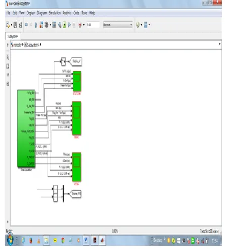
Figure 4.2 show the comparison simulink model between STATCOM, SSSC and UPQC
[image:4.595.40.279.422.651.2] [image:4.595.315.538.463.710.2]© 2016, IRJET | Impact Factor value: 4.45 | ISO 9001:2008 Certified Journal | Page 1262
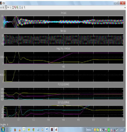
Figure 4.3 show the harmonic elimination on the basis of STATCOM
Fig 4.3 Harmonics elimination on the basis of STATCOM
[image:5.595.307.584.153.411.2]Figure 4.4show the harmonic elimination on the basis of SSSC.
Figure 4.4: Harmonic elimination on the basis of SSSC
Figure 4.5 show the harmonic elimination on
the basis of UPQC.
4.5 Harmonic elimination on the basis of UPQC
5. CONCLUSIONS
The above simulation shows the complete results waveform of all the three taken Facts Devices. The results show that among these three SSSC, STATCOM & UPQC, the UPQC Controller is the best to give the output waveform in the stable and the desired manner. The investigation with a Shunt Active Filter for installation on a power distribution system with mainly focus onharmonic reduction and voltage regulation performance has been successfully demonstrated in MATLAB/Simulink. Harmonics generated in the distribution system through non linear diode rectifier load, which is significantly reduced by UPQC
REFERENCES
[1] Proposed terms and definitions for flexible AC transmission system(FACTS), IEEETransactions on Power Delivery, Volume 12, Issue 4, October 1997, pp. 1848–1853. doi: 10.1109/61.634216.
[2] Electrical Machines, Drives and Power Systems, 6th Edition, p. 820.
[image:5.595.36.280.496.750.2]© 2016, IRJET | Impact Factor value: 4.45 | ISO 9001:2008 Certified Journal | Page 1263 [4] Gyugyi, L.; Schauder, C.D.; Williams, S.L.; Rietman,
T.R.; Torgerson, D.R.; Edris, A. (1995). "The unified power flow controller: A new approach to power transmission control". IEEE Transactions on Power Delivery 10 (2): 1085. doi:10.1109/61.400878. [5] N. G. Hingorani, L. Gyugyi, "Understanding FACTS; Concepts and Technology of Flexible AC Transmission Systems," IEEE Press book, 2000.
[6] L. Gyugyi, "Dynamic compensation of ac transmission lines by solid-state synchronous voltage sources," IEEE Trans. Power Del., vol. 9, no. 2, pp. 904-911, Apr. 1994.
[7] SIMULATION OF REAL AND REACTIVE POWER FLOW CONTROL WITH UPQC CONNECTED TO A TRANSMISSION LINE, 1S. Tara Kalyani, 2G. Tulasiram Das.
[8] Unified Power Flow Controller (UPQC) for Dynamic Stability in Power
System using
[9] Modern Control Techniques, B.Gopinath, S.Suresh Kumar, Juvan Michael.
[10] Implementation of Unified Power Flow Controller (UPQC) for Power Quality Improvement in IEEE 14-Bus System, Arup Ratan Bhowmik1, Champa Nandi2. [11] Vibhor Gupta, “Study and Effects of UPQC and its Control System for Power Flow Control and Voltage Injection in a Power System”, International Journal of Engineering Science and Technology, vol.2 (7), 2010, pp-2558-2566.
[12] Distributed generation and FACTS Technology - Wikipedia, the free encyclopaedia.
[13] J. Hao, L. B. Shi, and Ch. Chen, “Optimizing Location of Unified Power Flow Controllers by Means of Improved Evolutionary Programming”, IEE Proc. Genet Traosm, Distrib 151(6)(2004),pp.705-712.
[14] S. Baskar, N. Kumarappan and R. Gnanadass,“ Switching Level Modelling and Operation of Unified Power Flow Controller”, Asian Power Electronics Journal, vol.4, No.3, December 2010.
[15] M. A. Abido, “Power System Stability Enhancement using FACTSControllers: A Review”, The Arabian
Journal for Science andEngineering, Volume 34, Number 1B, April 2009.